 Arya
Arya
Some time ago, I found an article about modding soldering stations for safety (in Russian) (Google Translate). The problem is hot air guns suddenly melting and setting themselves on fire, supposedly, because TRIACs that control them fail.
Here's a video of this phenomenon:
Here's one more:
First, an explanation on how most Chinese hot air guns work.

why would you point the hot air gun towards the desk ffs
and the soldering iron too what the fuck is this picture
and the sponge isn't even wet
my eyes hurt
Most of soldering stations have simple hot air guns - with air pump (a small fan, to be exact) embedded in the gun itself. So, in the hot air gun you'll have a fan, heater, thermocouple and sometimes a reed switch to detect when hot air gun is put on its stand, there might also be a ground wire connection if you're lucky (to be fair, it's there most of the times). It's all plugged in and controlled by a separate box, which might also control a soldering iron if you bought a combo hot air+soldering station, and that controller box is powered by 220V.
The hot air heater consumes plenty of energy, there's air going through it constantly, and it has to keep the temperature up. From my understanding, there are two ways to power heaters like this - either from 220V, or from a separate box. First option is kinda less safe (since, depending on which way you put the plug in, you might have 220V inside your hot air gun), but significantly cheaper and simpler to be implement. It can be also made in a safe way, of course, the problem is when it's not done that way.

So, here's a typical circuit for driving a TRIAC. The middle block is an optocoupler with an integrated TRIAC driver, something like MOC3041 (has zero crossing detection, helps decrease losses when driving AC), that TRIAC driver controls the main, big TRIAC that switches Rload, and the Rload is our hot air gun heater. The optocoupler is driven by a microcontroller's GPIO, based on hot air gun temperature and settings that the user picked.
What happens when TRIAC fails and shorts itself? What happens if the optocoupler's phototransistor fails short, or the LED-driving-GPIO on the other side is stuck for some reason? The heater gets 220V, and for a small heater this isn't something it can handle for a long time.
Theoretically, those stations shouldn't just fail. However, it appears they do - be it cost-cutting practices, fake parts, bad PCB design or something else, like power surges - maybe all of those combined. Reading the article I was talking about, the most scary thing about it were the comments - full of remarks like "Yeah, my friend's room burned down because of that", "Yeah, I went away for an hour and saw my hot air gun melted and breakers blown". I think this is not acceptable, but I also don't think we can do anything other about it than hacking around the problem after we buy the station.
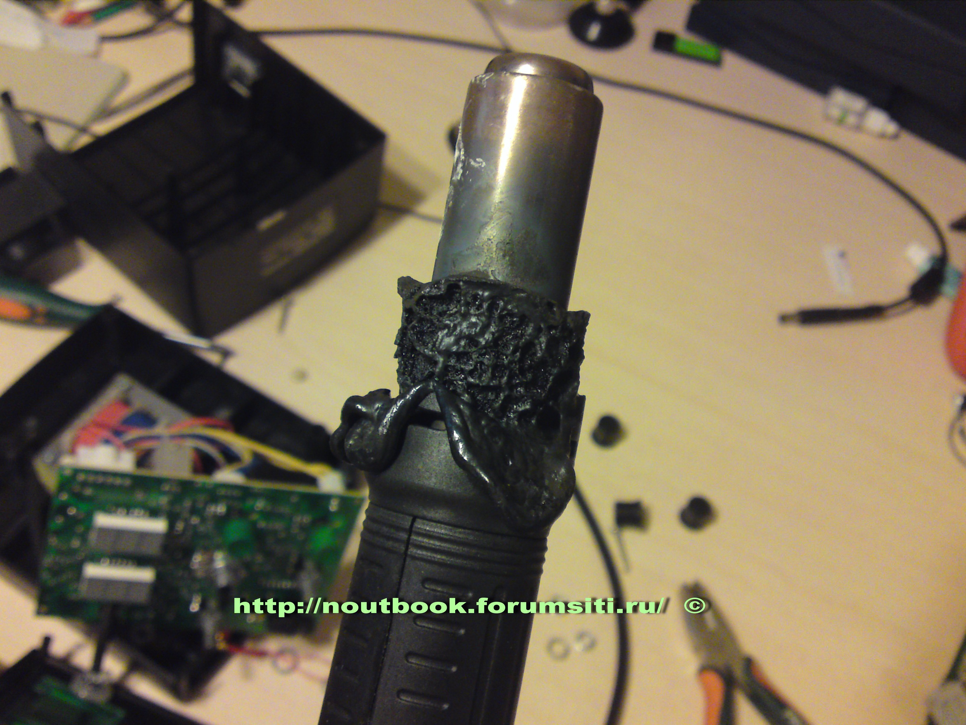
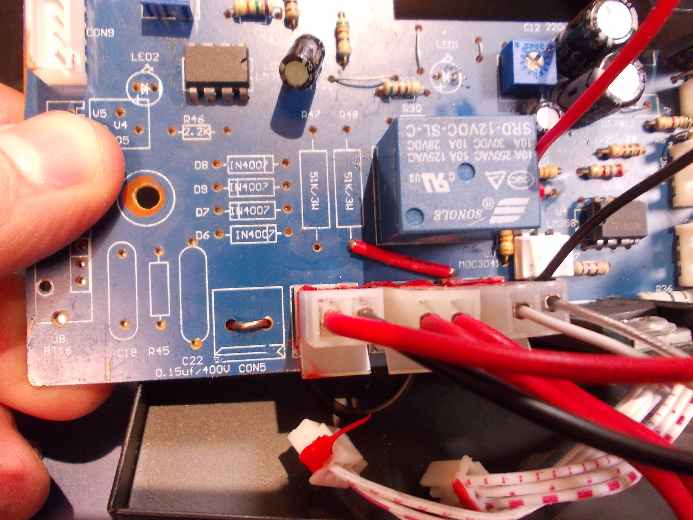
Our hackerspace has a soldering station, hot air+soldering iron combo. I was sure it'd have the same electrical design, so I decided I'd check if it's vulnerable.
Disassembling it:
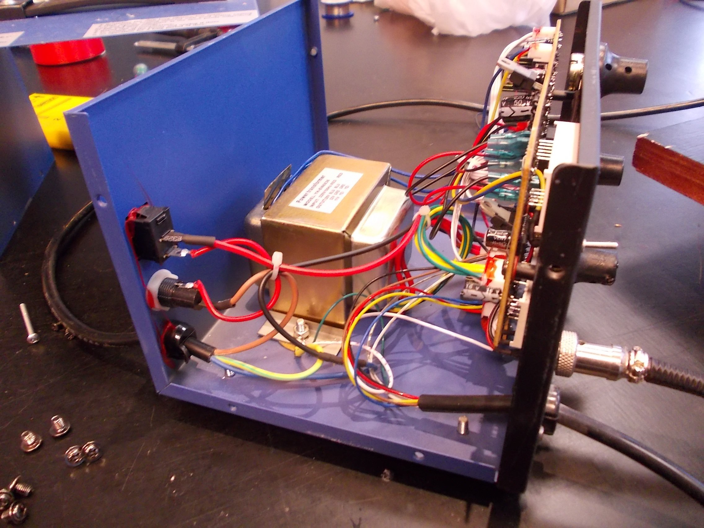
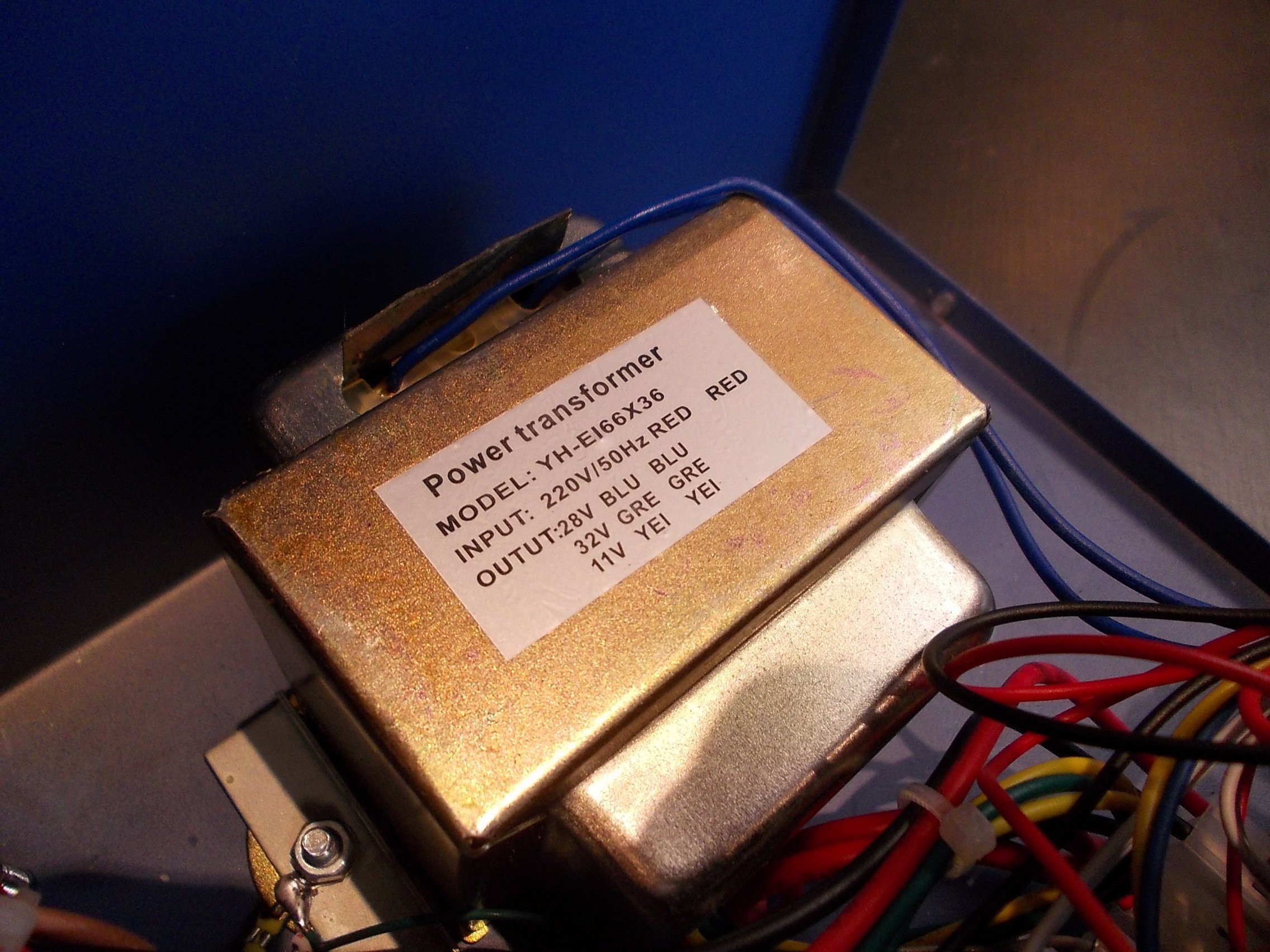

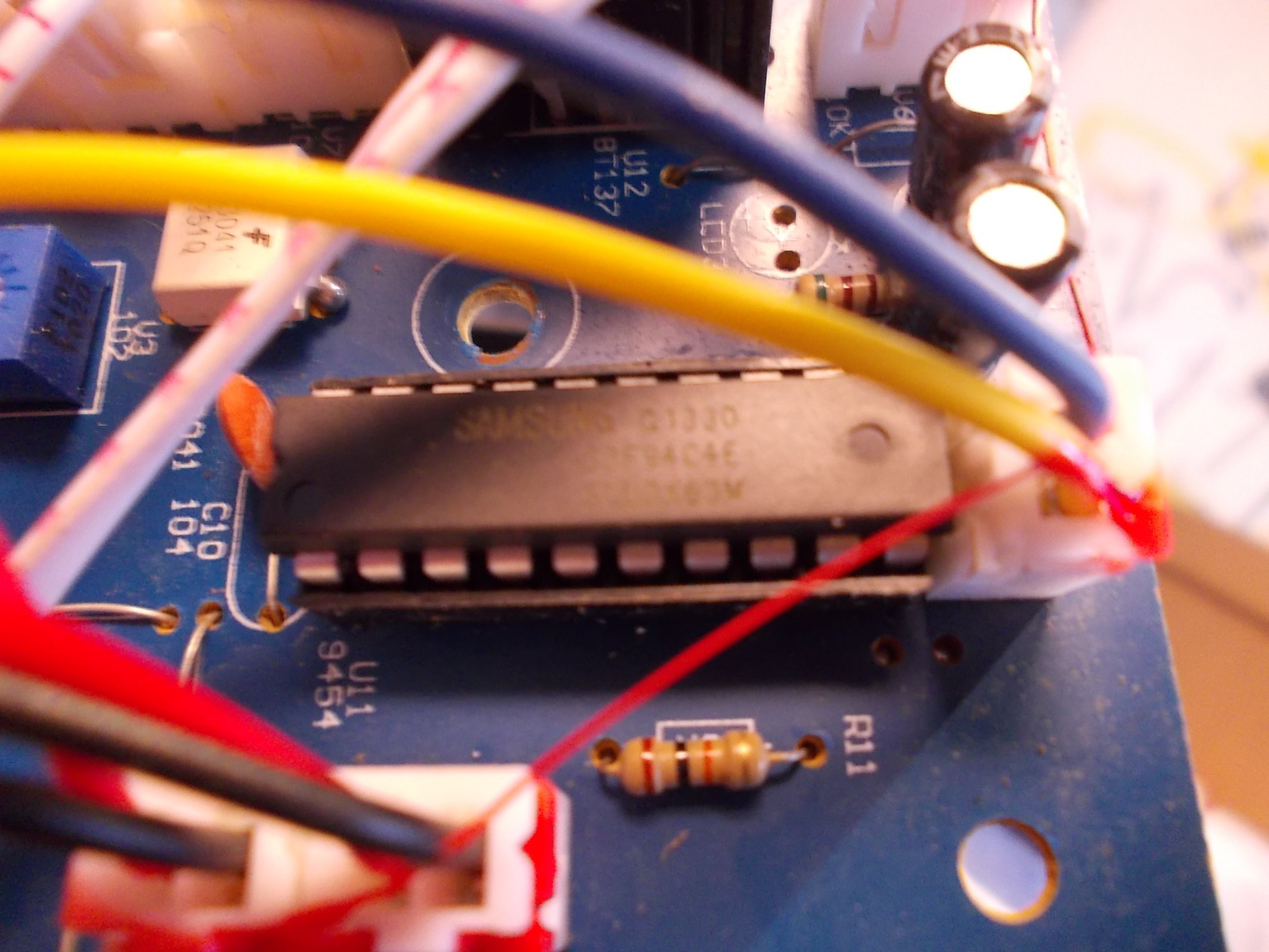
Yeah, same design - TRIAC and an optocoupler driving it. At least it all seems optoisolated. But hey, what's this?
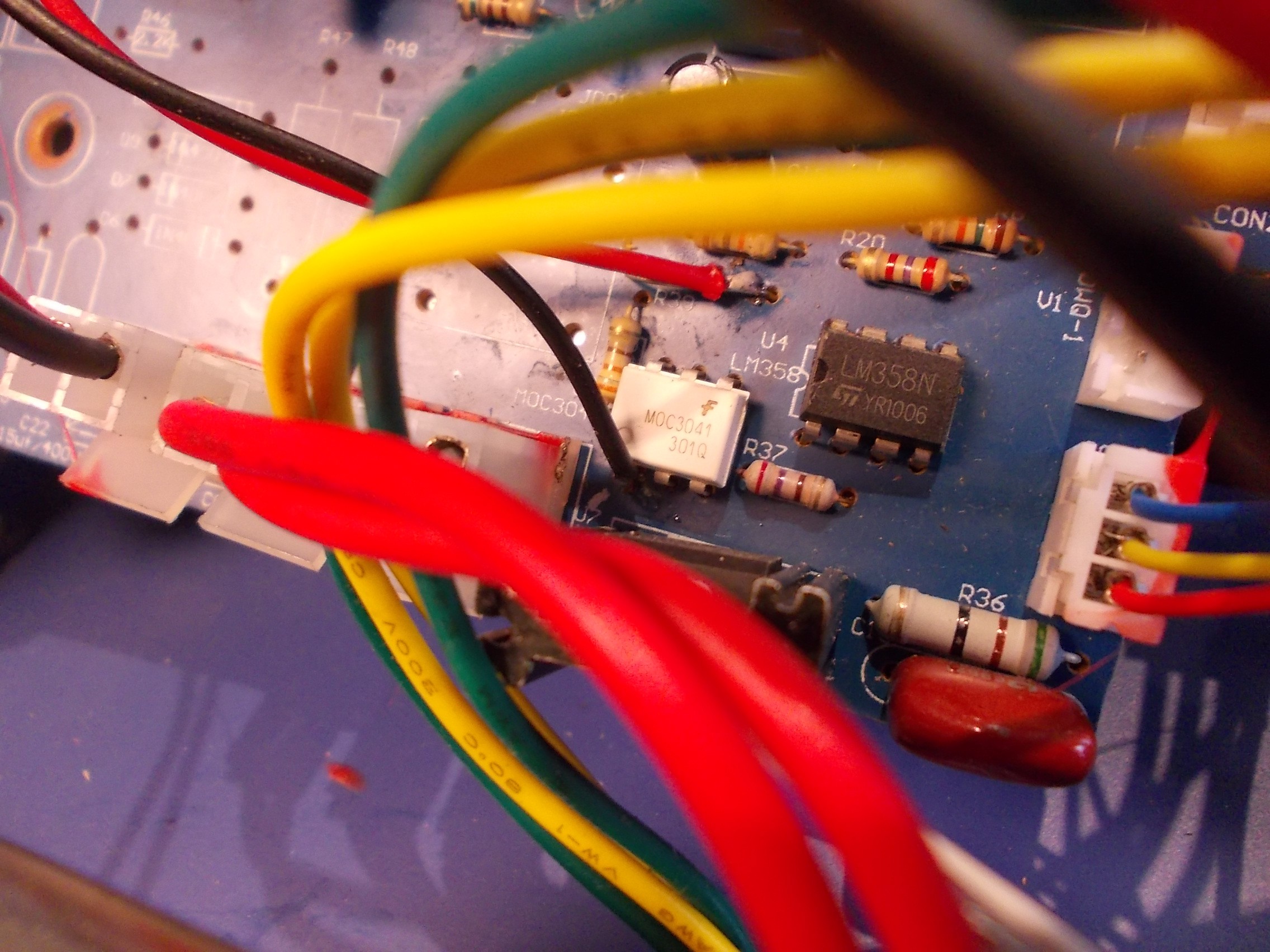
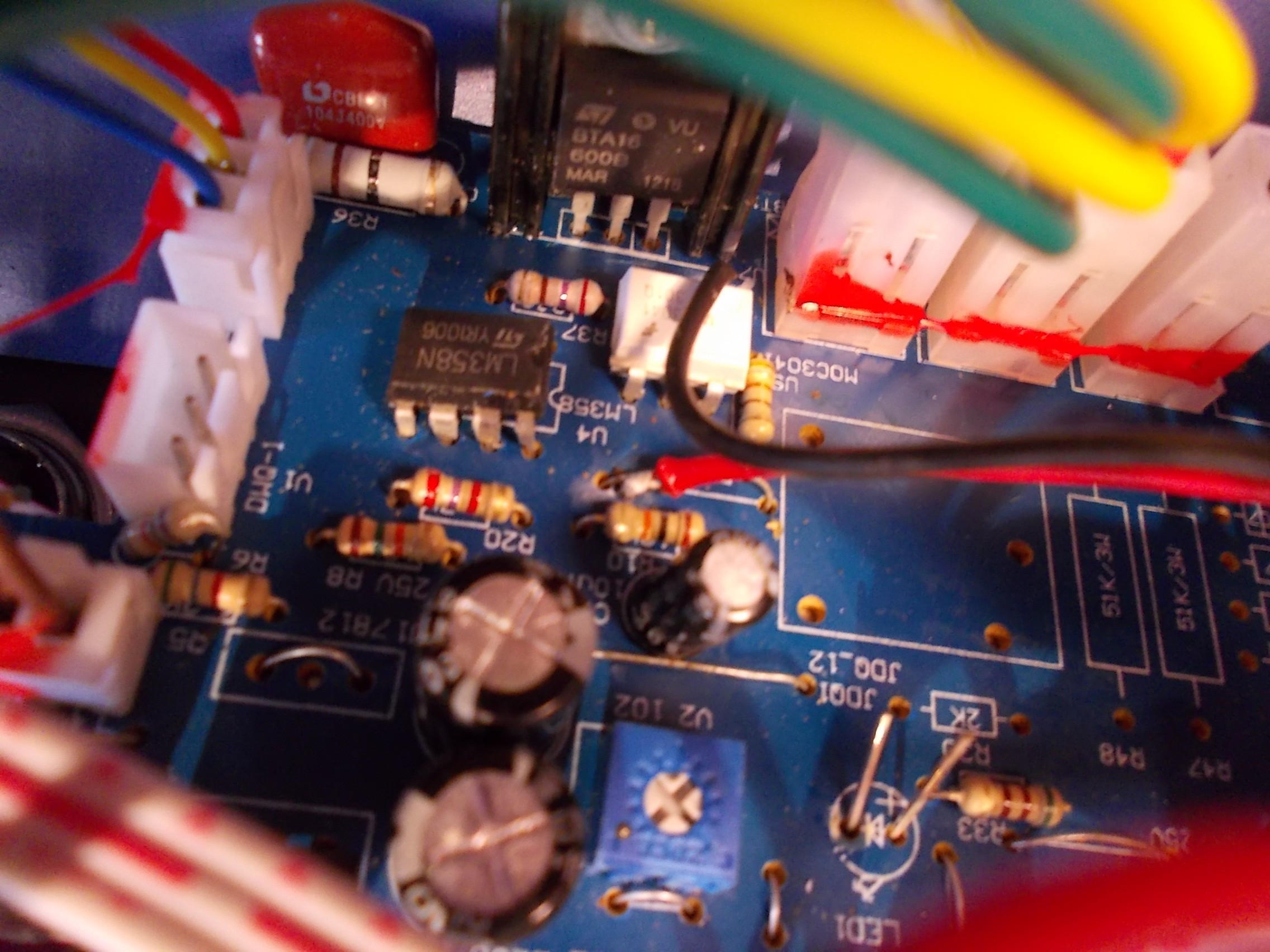
So, the manufacturer of this soldering station actually took some precautions - but only after the board was manufactured. He actually cut trace from optocoupler LED to one of the power connections, and added wires connecting the optocoupler to the same switch on the front panel that enables the hot air gun. So it appears, from one side the optocoupler LED is controlled by PWM from an onboard microcontroller, from the other side it's controlled by the switch that, being SPDT, signals the MCU to start PWMing with one pair of contacts and enables the optocoupler with other pair.
This is a nice touch (as well as something that shows the problem exists and is known). However, IMO this isn't enough. What if the phototransistor side of optocoupler fails? What if the main TRIAC fails? I'm sure it still needs a relay.

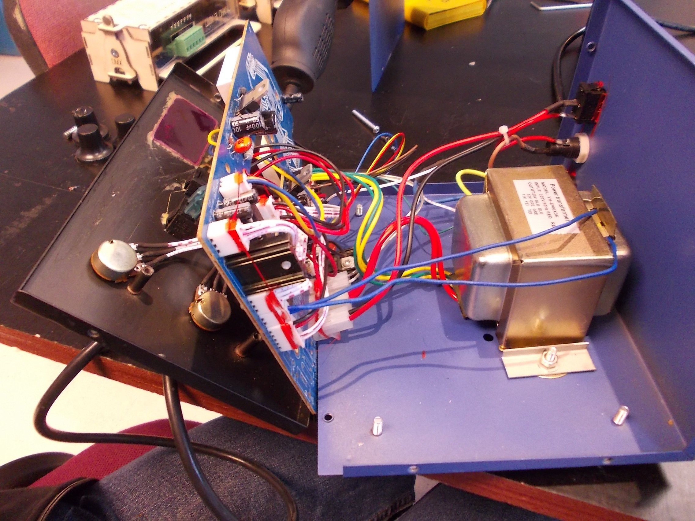
There's a relay footprint, too! I didn't understand what it was for, what kind of device would be connected to it, could be some kind of cool accessory. Maybe this board is multi-purpose, and is also used in something else other than soldering stations?
So, I can use that footprint to easily wire a relay in - I don't have to add any additional wires, that's nice. This footprint is for the kind of the relay that we usually get in "Arduino 5V relay breakout boards", except this relay is wired to 12V, as quick check with a multimeter revealed. I had one of these relays that was 12V-compatible, left over from a previous project, so I added it in!
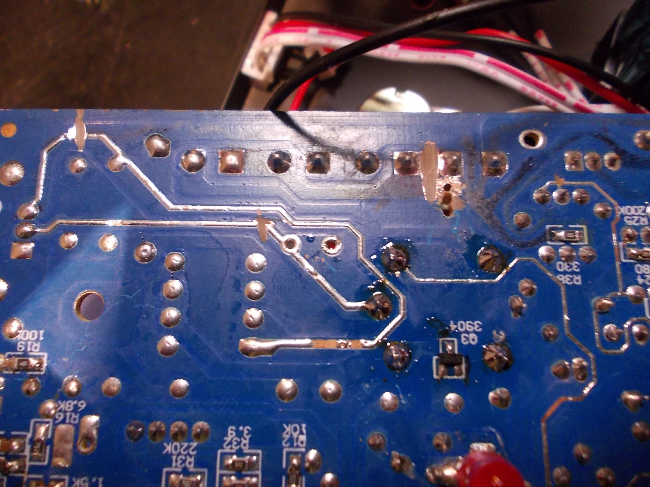
Now, the power trace part needs some re-wiring. Armed with a dremel tool, I cut some traces, drilled a pair of holes and added some jumpers:
How it would be controlled, though?
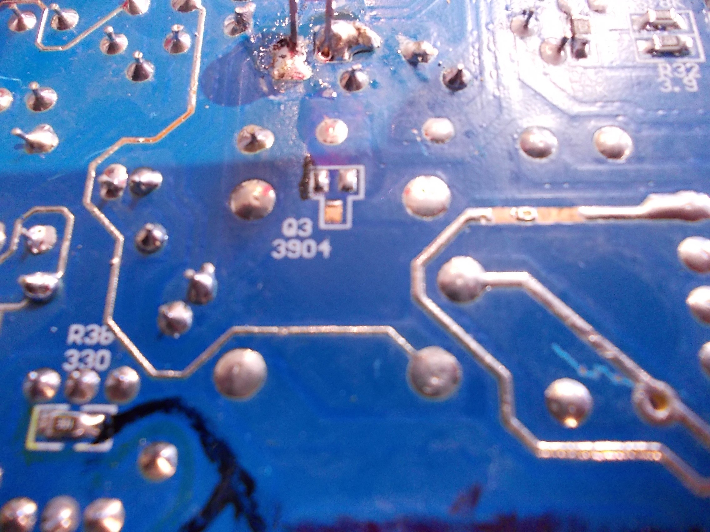
Ah, there's a transistor footprint, nice. Needs a base resistor and a resistor between base and ground, though. Done:

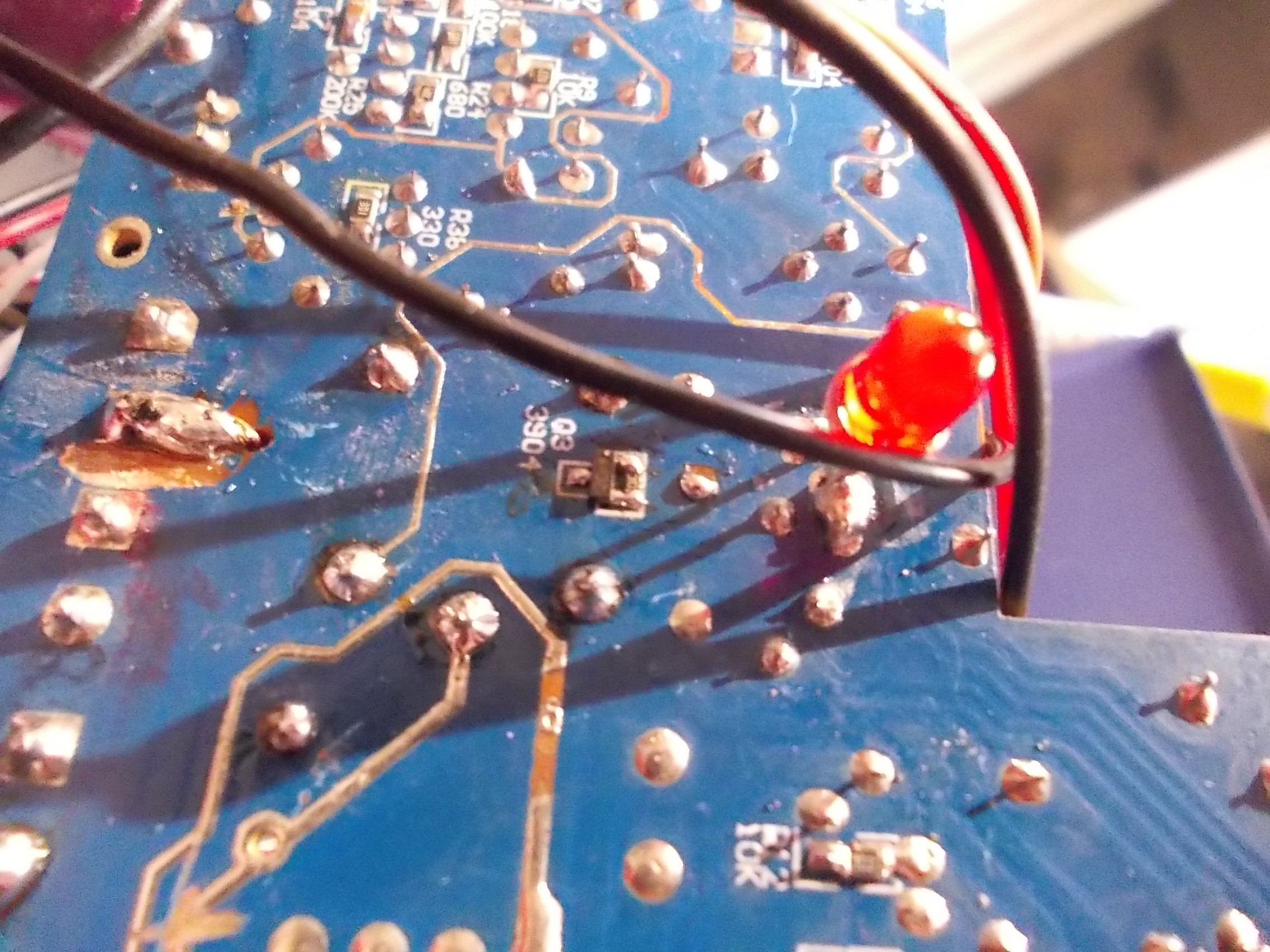
Seems to be it!
Later on, I realised I forgot a diode in parallel with relay, though. However, as far as I can imagine, worst case is - the relay is going to be stuck open, making it all no less safe than it was before. Also, I can easily check whether the transistor is still working, by turning the soldering station on and then flipping the "Hot Air" switch - if the transistor is OK, I'll hear the relay click =) (and if the transistor breaks, the relay will likely just never turn on, which could be taken as "fails in a safe way").
Problems that this hack doesn't solve:
- Heat gun melting while the station is on and the heat gun switch is on - if the heat gun gets constant 220V while it's on (and, say, air is set too low, or even stops because of the blower fan melting), it still might start melting and go up in flames, maybe not as quickly. Same could happen in case there's a voltage spike which makes the microcontroller go haywire and turn the TRIAC 100% on. To be safe from that, you'd want some kind of relay that would protect from overvoltage.
- However, if both the station and the heat gun switch are on, you're likely somewhere nearby - right?
Anything else?
Discussions
Become a Hackaday.io Member
Create an account to leave a comment. Already have an account? Log In.