 Michele Perla
When I first thought about redesigning the CORE my main goal was to use one Teensy to control at least one IOAPEX module and two CODEC modules, to reduce the overall cost of a full system (one Teensy 3.6 is at around 30 $), to reduce the number of duplicated parts over the modules or, in other terms, to agglomerate the mandatory common parts in one module. These common parts are, again, the Teensy, but also the USB port, MIDI ports mainly.
Minimum Common Denominator
I for one don't like having to reserve one USB port for my audio interface and another one for my USB MIDI controller, and with the increasing number of laptops that sport less and less connectors for peripherals I suppose that the average user would like to have MIDI+Audio over one single USB cable, too.
Secondly, to get more flexibility out of the CODEC modules I want to use low-jitter I2S master clock generators, in the form of two selectable oscillators that output 22.5792 MHz and 24.5760 MHz, but I don't want to have two oscillators near each AK4558 codec, it would take more resources (PCB real estate, Teensy pins to enable/disable them, actual component cost). I'd rather have them near the Teensy.
Third, the Teensy requires a 5 V power supply, which may or may not be available in an Eurorack system, so I'd like to have a small switching supply to convert the readily available 12 V from an Eurorack supply to 5 V (switching rather than linear because a 12-to-5 V linear supply would dissipate more power than it would be ever needed by the whole module).
This need for a main, minimum common denominator, module is why the CORE is now, well, the core module of the MAD project.
This also sets the CORE as a must-have thing for a MAD-powered setup, and to justfiy the eventual price of this module I can't just make it something that has a USB port and MIDI IN and OUT. I need features.
Available Resources
A Teensy 3.6 has a LOT of pins, but a lot of them are reserved for the IOAPEX, for the two CODECs, for the I2S external clocks, for the TFT, and for the MIDI ports.
In particular, the IOAPEX requires full control over an SPI port, plus a reset pin and the two ADC channels.
The two CODECs share 3 I2S pins (master clock, bit clock, frame select), then there's a TX and RX pin for each codec (4 total), one GPIO for each codec (for powering it down), and they also share the I2C bus (two more pins).
The MIDI ports take only two UART pins.
The two I2S master clock generators take one pin each and they share their output on the I2S MCLK pin (when one clock is disabled its output is in Hi-Z mode, thank you three-state outputs).
The TFT takes 5 pins (three SPI pins and 2 hardware chip selects).
About the SPI ports, the IOAPEX is going to be reserved on SPI2, the TFT on SPI0 (because the Teensy optimized TFT library makes extensive use of the SPI0 4 words FIFO), and this leaves a free SPI1 port. But, since I want to keep its pins for SPI instead of using them for GPIOs, the SPI1 pins are reserved too (4 pins). This is to allow future small upgrades (a RAM chip, or a Flash ROM maybe, or whatever). I'm also keeping untouched the common CS pins for the SD and memory expansions available on the Teensy Audio Adaptor in case someone wants to fiddle with them on a CORE.
All of this leaves us with 30 available pins; 3 are analog only pins A10, A11, and AREF but since the IOAPEX is going to make full use of the two ADC channels continuously they're a no-go; furthermore, I'm fine with the way the AREF pins is connected on the Teensy itself so I do not need to touch it.
So it's down to 27 pins, two of which are the two DAC channels. Not bad after all.
Features, you said?
This is where I thought about CV outs and Gate outs.
The DACs have already been used to output audio and CV, and driving a gate can be as simple as connecting one pin straight to a jack. Since there's going to be a USB port and MIDI ports already on the CORE, a USB/MIDI-to-CV functionality would be a great feature to justify the CORE module, making it a nice standalone module. This would also justify fitting a TFT for easy configuration of the CORE CVs and Gates, which in turn would require some means of navigating menus. Given that we only got digital pins available, we can use encoders with integrated buttons.
So, where are the multiplexers?
Well, the DAC only has 2 channels, but to get a decent amount of CVs we can multiplex them! But to get a decent muxed output, we need sample&hold circuitry too!
My idea is to use a dual 4:1 analog multiplexer to split the two DACs on 8 separate outputs; every output has a S&H circuit made of an opamp with gain to convert the DAC out from 0-3.3 V to 0-10 V, then there's two more opamps used for coarse and fine offset control (from 0-10 V to -5/+5 V out with a +/-20 mV calibration). This is the LTSpice schematic I used to simulate one DAC, the mux, and the opamps.
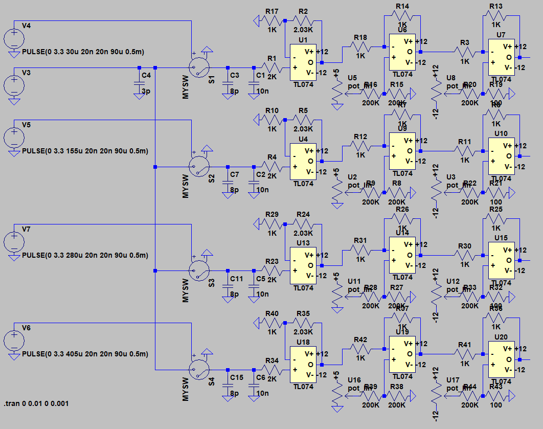
The simulation also accounts for mux output capacitance and mux on-resistance.
I might add a third potentiometer in the S&H+gain stage for precise calibration of the gain (you know, to get a perfect 0-10 V signal). I'm thinking of using multi-turns trimmers for each control, but I think that a normal pot would be better for the coarse offset control because it would be the most used controls out of the three. In fact, the gain and fine offset would need to be calibrated once, while the coarse offset would be changed often, say if someone uses it to control a synth with a -3/+8 CV range and then wants to use the same CV with a -5/+5 CV range.
Using this technique I can get 8 CV outputs that could be used for example for two Note+Velocity+Pitch bend+Modulation CVs, or for 8 independent Note CVs.
One dual 4:1 mux would require 2 control pins, and one enable pin, so this leaves us with 24 available digital pins.
Since I'd like to have 4 encoders+buttons, they would require 8+4 pins, leaving us with 12 available pins. To complete the 8 analog CVs, I think 8 Gate outs are enough. Having at least one Gate in would be beneficial too, to be used as a Clock/Sync input.
If I was to use one digital pin for each gate signal I could still have 3 digital pins left, in case I was to use a technique similar to the one used for the DACs, I could multiplex 2 digital pins and use 3 digital pins to control said mux, reducing the number of pins used from 8 to 5, leaving us with 6 digital pins.
I already made a similar LTSpice simulation for the digital pins muxing, as seen here:
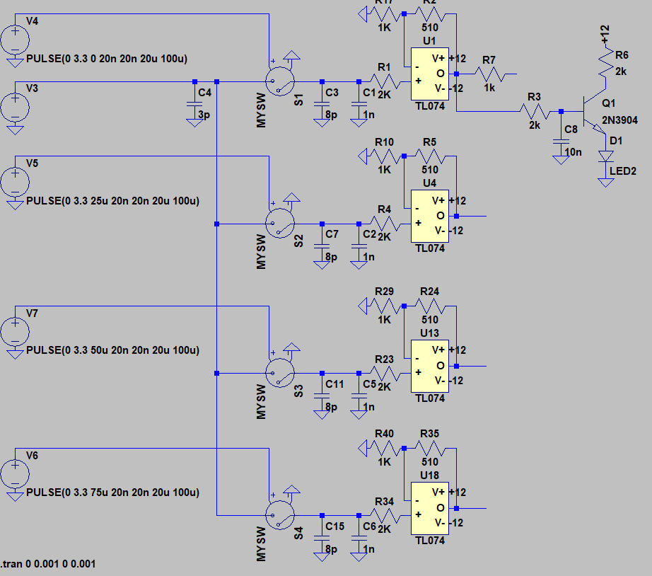
I also put a transistor to drive a LED from the first Gate out just to see how it would work. The 10n cap on the base is useful to reduce current spikes in the LED when the transistor turns on/off, to avoid introducing switching noise in the main power supply.
Surely, using 8 separate pins to control the 8 gate outs will reduce components count (one less mux for starters), so I think I'll go this way for now.
Conclusion
I still do not know how many options will be controllable using the TFT+Encoders interface, but some functions I'd like to have are to rapidly assign MIDI channels to CVs (say, one Note CV assigned to a USB Midi channel 1, one Note CV assigned to physical MIDI channel 1, etc), to change the CVs configuration (from 2x Note+Vel+Pitch+Mod to 4xNote+Vel or Note+Pitch, to 8x Note etc), to control onboard sequencers (this would add SO much value to the CORE, too), and stuff like that.
But I do know what I want to put on the CORE and this is a milestone by itself.
I'm going back to work now :)
Cheers,
Mick
Discussions
Become a Hackaday.io Member
Create an account to leave a comment. Already have an account? Log In.