-
The Practical Hardware Design Guide: MSP430
03/29/2022 at 17:02 • 0 comments![]()
MSP430™ is a 16-bit microcontroller of Texas Instruments. In this tutorial, we will create basic hardware for controlling LED strips.
The Microcontroller
![]()
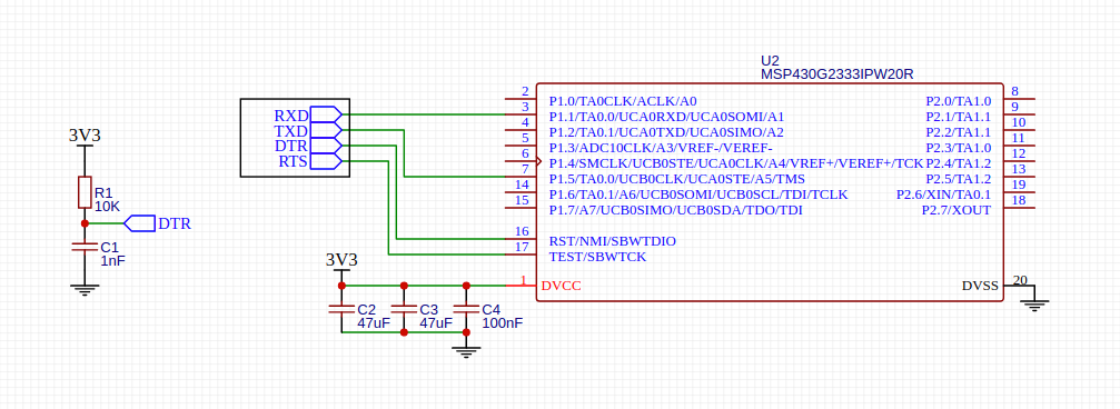
We will use MSP430G2553, with 512B of RAM and 16kB of Flash program memory. This is sufficient for implementing many features, such as I2C OLED display driving, rotary encoder interfacing, motor control, etc.
Some variants of MSP430 have very small RAM. For example, MSP430G2211 has only 128B of RAM. For simple LED blinking and PWM controls, this may be enough. But for more advanced jobs such as OLED display control and interfacing I2C sensors, it's common to exceed the RAM usage. When building binary files in Energia or CCS IDE, the RAM and ROM usage is printed out. But if you're still in the early stage of firmware development or you're not sure how much RAM it will use, just try to use the highest model of MSP430 available.
As we will use a USB-serial converter for programming the MCU in this tutorial, we need to choose an MCU with a serial bootloader. Most of the MSP430 has a serial bootloader on ROM, called ROM-BSL. But not all the MSP430 have it. Some very low-end variants like MSP430G2211 have no ROM-BSL feature. For these chips, a 2-wire Spy-Bi interface can be used with a dedicated programmer/debugger like MSP430UIF.
For MSP430, choosing a delay capacitor (C1 on the diagram) is important. If this capacitor value is too big, the Spy-Bi-Wire cannot work, because the same pin is used for the data line in debug mode. The recommended values are 1nF for a 10k pull-up resistor.
Another common mistake is wiring the USB-serial converter's RX to MSP430's TX pin (P1.2 of MSP430G2553). This is valid for using UART communication. But for ROM-BSL, a different pin (P1.5 of MSP430G2553) must be used.
Section checklist:
- Available RAM/ROM size of MCU
- Presence of ROM-BSL functionality of MCU
- The right value of the pull-up resistor and delay capacitor
- RX/TX wiring for ROM-BSL usage
USB Programming interface
![]()
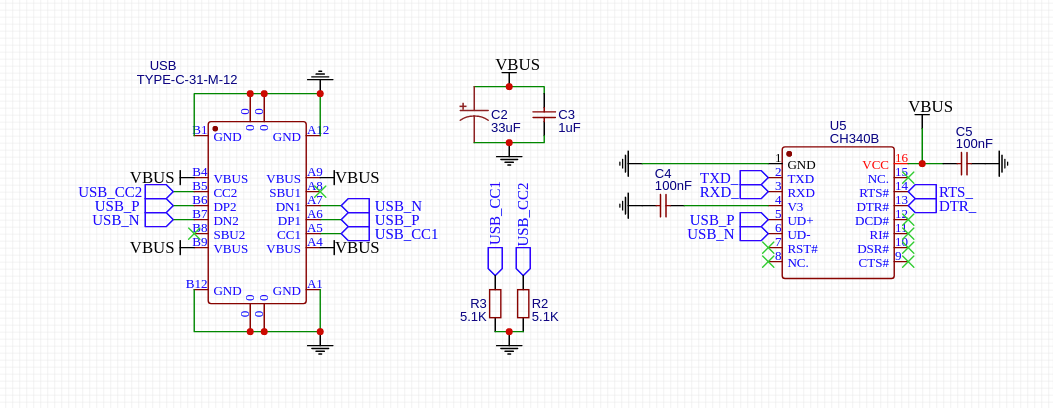
There are several common USB-serial interface controller ICs, such as FT232, CP2101, PL2303, CH340. The ROM-BSL feature requires 4 pins - TX, RX, DTR, RTS. Note that not all USB-serial converter chips have all these pins available. For example, some CH340 and PL2303 variants do not have DTR or RTS pins.
CH340C and CH340B both have all 4 pins. But as CH340C requires an external crystal oscillator, we'll use CH340B for this example design.
USB Type-C port is widely used to replace the legacy USB micro-B and mini-B ports. In practice, USB-C ports are more strong mechanically. When using a USB Type-C port, be sure to use pull-down resistors for CC pins. These pins are used to tell the USB PD supply to get 5V power. Without these pull-down resistors, the board cannot be powered from USB-PD type supplies such as mobile phone chargers.
Section checklist:
- Availability of all 4 pins - RX, TX, DTR, RTS
- Pull-down resistors on USB Type-C's CC pins
Power supply and IO
Some PIC or AVR microcontrollers work for a wide power voltage range, e.g. 2~5.5V. But all MSP430 microcontrollers work only under 3.3V and don't accept 5V VCC. Make sure to use some 3.3V LDO or switching power supply.
Because the VCC is 3.3V, all the IO levels are 3.3V. This may be a problem for driving high-current MOSFETs directly. For example, to make a 50N06 (50A, 60V N-Channel MOSFET) fully open, the gate voltage should be greater than 5V. In this case, need to use a small MOSFET (e.g. 2n7002) for driving high current MOSFET.
Section checklist:
- 3.3V power supply
- All I/O must be compatible with 3.3V
Full Design Example
Here are full design files in EasyEDA format for a LED lighting controller board as an example.
![]()
Prototyping with SMT Assembly Service
These are the fabrication files that can be directly uploaded to JLCPCB's online ordering form. These files can be exported from EasyEDA's Fabrication menu after editing the designs.
Read more » -
Prototyping KiCad-Designed RP2040 PCB Using JLCPCB SMT Assembly
03/29/2022 at 16:41 • 0 commentsIn this article, we will explore how to get a KiCAD design fabricated and assembled by the JLCPCB SMT Assembly service.
Prerequisites
If you're reading this article, you'll probably have KiCAD installed on your computer. But if not, download and install KiCAD 6 from the official website.
The following contents of this article is tested with KiCAD version 6. Older versions or Nightly builds are not tested.
There are several plugins to export JLCPCB compatible fabrication files (Geber, BOM, CPL). As we can see in the table, KiCAD JLCPCB tools has the best reputation and community support (at this time of writing).
GIthub Repository Star Fork Contributors Last Updated KiCAD JLCPCB tools 244 28 10 Feb 2022 KiCad JLCPCB BOM Plugin 110 25 3 2021 KiJLC 12 8 2 2021 KiCad BOM CPL Plugin 3 2 1 2020 Install KiCAD JLCPCB tools on KiCAD as described in the doc.
- open KiCAD
- go to menu Tools > Plugin and Content Manager
- in the Plugin and Content Manager dialog, click the Manage button
- in the opened Manage Repositories dialog, click + button
- copy and paste the following repository metadata URL https://raw.githubusercontent.com/Bouni/bouni-kicad-repository/main/repository.json
- Click Save button
- Click the dropdown named KiCad official repository and select Bouni's KiCad repository
- Click the Install button of the KiCAD JLCPCB tools item on the left panel
- close the Plugin and Content Manager dialog
If installation worked, you could see a blue JLCPCB tools icon on the toolbar of PCB Editor.
Starting from an Existing Design
Immature poets imitate: mature poets steal. by T.S. Eliot
Just like graphics designers start from templates and software developers start from boilerplates, hardware designers can also start from a template or existing designs. There are already many resources we can use, including the official Raspberry Pico design. To help you to choose the right starting point, the following table summarizes some open-source hardware designs at the time of this writing.
>td >Pro Micro RP2040
Project/Board Name Author Resource Designed with Note Raspberry Pico Raspberry Pi Foundation Design File Allegro The official hardware design of Raspberry Pico ItsyBitsy RP2040 Adafruit Industries GitHub Eagle ItsyBitsy footprint RPi Pico Debugger Shoe Shawn Hymel GitHub KiCAD Raspberry Pico footprint We'll use RPi Pico Debugger Shoe as a starting template, because
- it's designed with KiCad
- it has the same pinout as the official Raspberry Pico board
- this article is not for replacing other Raspberry Pico design howto guides like the official guide.
But you can choose other resources as there are ways of importing Eagle and Allego designs from KiCad, or even you can create the design from scratch.
Editing the design
Since we started from an existing design, let's say editing the design instead of designing the hardware.
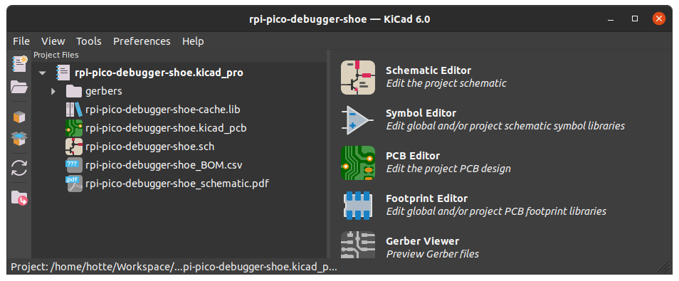
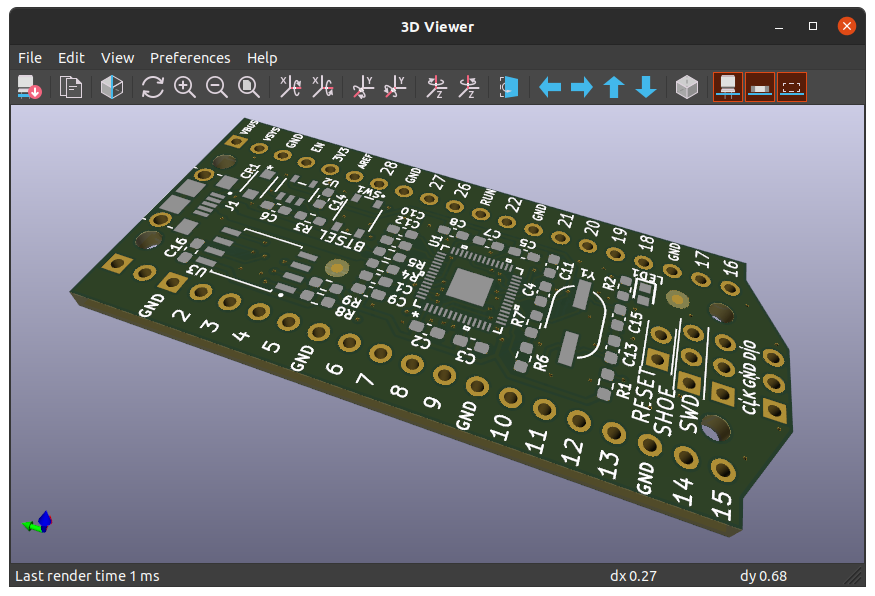
First of all download and open the design in your KiCad. Some may do it by simple mouse clicking on the web browser, others would do it using the Git command line. No matter how you downloaded it, you could see the following result after opening it.
![]()
![]()
You could change whatever in the design as your need. But before publishing and using it in production, be sure to check the license of the original project.
We will assume that you changed something and are ready to go for prototyping with the JLCPCB SMT Assembly service.
Generating the Files for JLCPCB
Unlike some other PCBA manufacturers where the BOM, Geber, CPL files are treated manually by the sales and engineering employees, JLCPCB offers the online form to upload the files to get PCBA ordering done. JLCPCB was one of the early suppliers that supported online ordering on the website. Online PCBA ordering has pros and cons.
- Pros
- transparent pricing, no hidden costs
- 24/7 instant ordering...


 Lutetium