 HyTech Racing
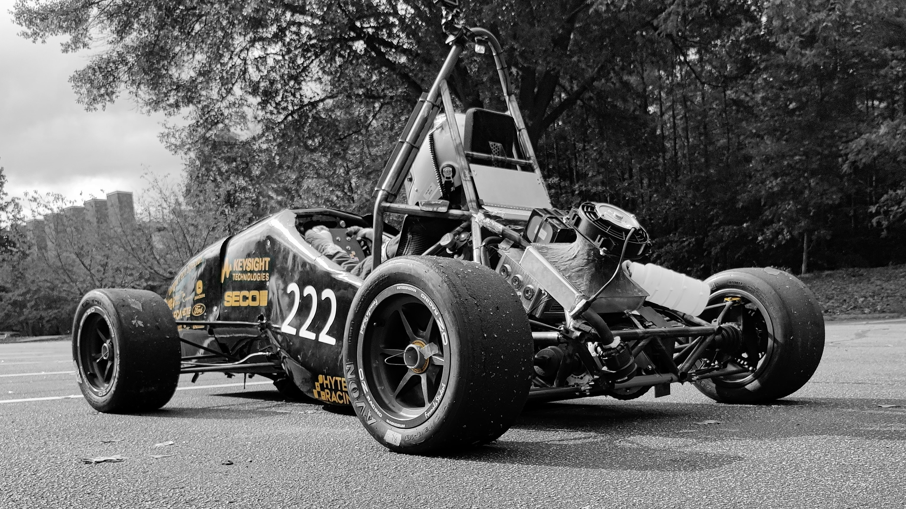
HyTech Racing is an award-winning student-run organization at the Georgia Institute of Technology dedicated to furthering students' engineering experience through the rigorous design and development of Formula Student electric vehicles. Every year, we design, build, and race a brand new student-designed single seater electric formula style racecar. Thanks to JLCPCB for providing us with this sponsored PCB.
I. Introduction
The charger controller board is used in our electric formula-style racecar to manage our battery pack's charging in a safe, efficient way. This custom designed board has many features, focusing on both safety and data collection. The brains of the board lies in two microcontrollers, a Teensy 3.2 for the main controlling of the charger and safety features and a Teensy 3.5 for data logging.
II. Shutdown Circuit
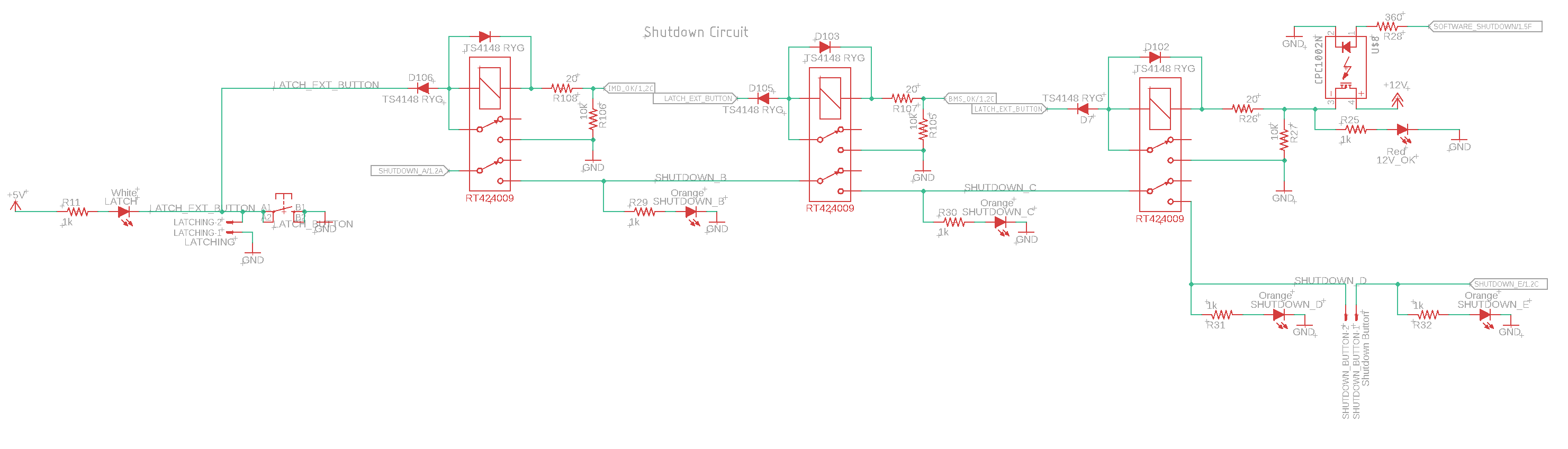
Figure 1. Schematic of the shutdown circuit including the relays and latching circuitry.
The shutdown circuit is the main safety feature of the board, consisting of three stages. Each stage must be active (driven high) in order for charging to commence. Each of these three signals also contain a latching circuit to ensure once a fault happens, the charger remains off until the issue is resolved and the system is reset. An isolated relay is used to control the charger control signal to prevent damage if a fault in the charger occurs.
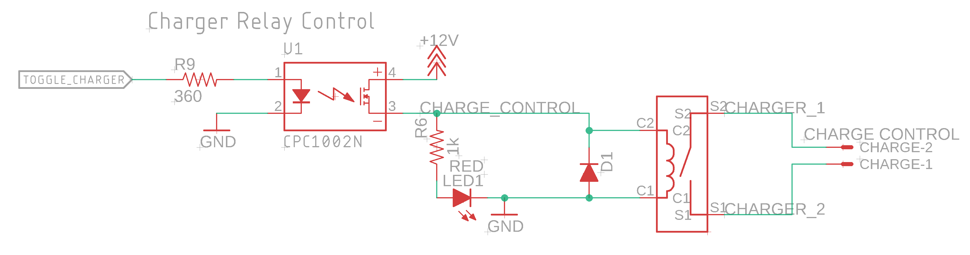
Figure 2. Schematic showing the isolated control signal between the shutdown circuit and the chargers toggle.
Car's Shutdown Signals
Onboard the car, there are many additional fault systems in place, including a signal that provides the status of the battery management system (BMS) and another signal providing the status of the insulation monitoring device (IMD). These two signals, the IMD_OK and BMS_OK, are directly connected to individual relays in the shutdown circuit on the board. If either of these signals are low, the shutdown circuit will immediately trip, stopping the charge until the issue is resolved and the system is reset.
E-Fuse
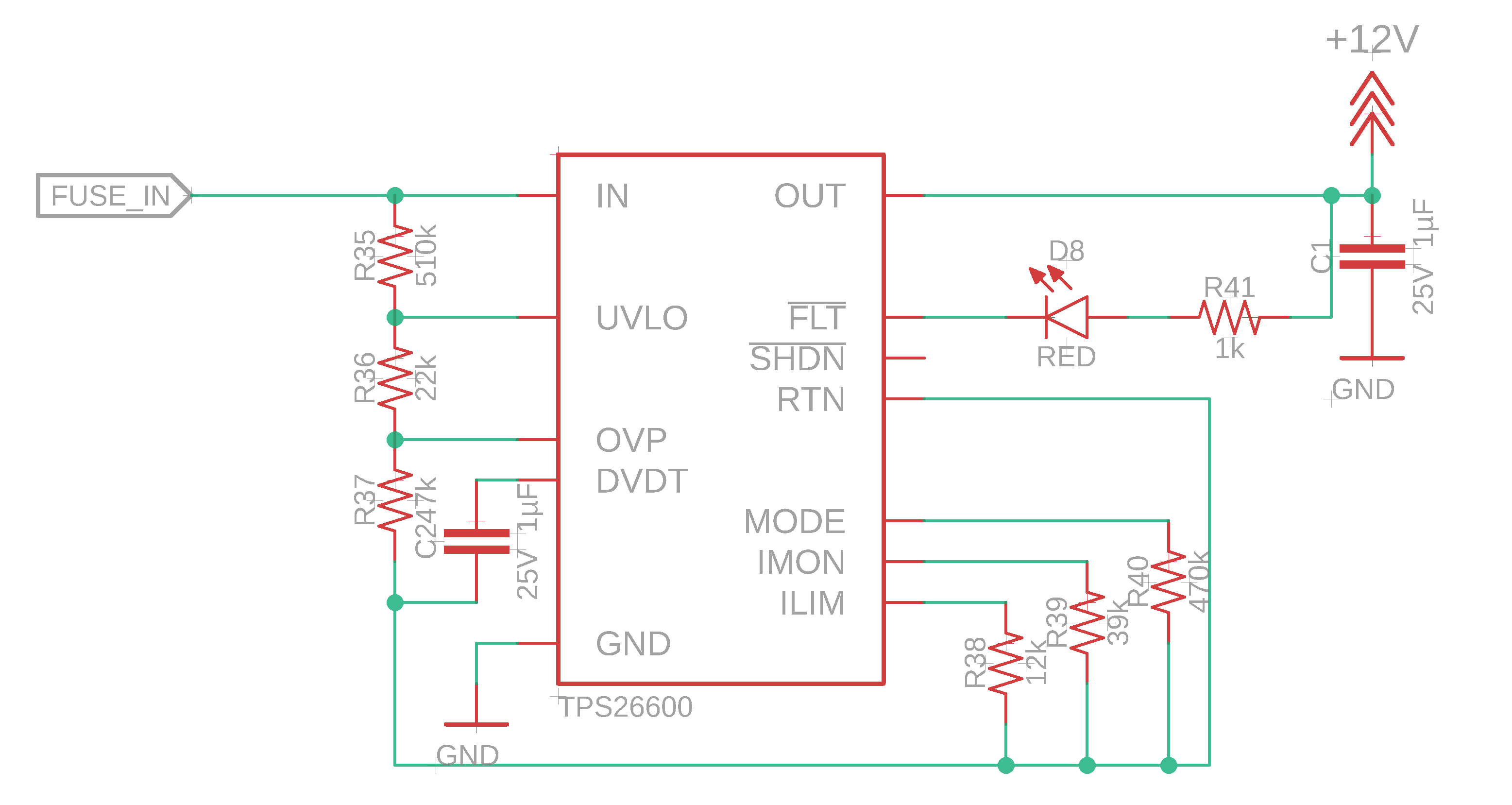
Figure 3. Schematic showing the implementation of the e-fuse into the board.
The E-fuse is the second safety mechanism, monitoring the current flowing and providing information to the onboard Teensy 3.2. The Teensy can then deem the current to be a fault state (too high, abnormal, etc.) and shutdown the charger with the final relay in the shutdown stage. This current value is also displayed to the serial connection of the Teensy 3.2 for charge progress and monitoring.
Watchdog Timer
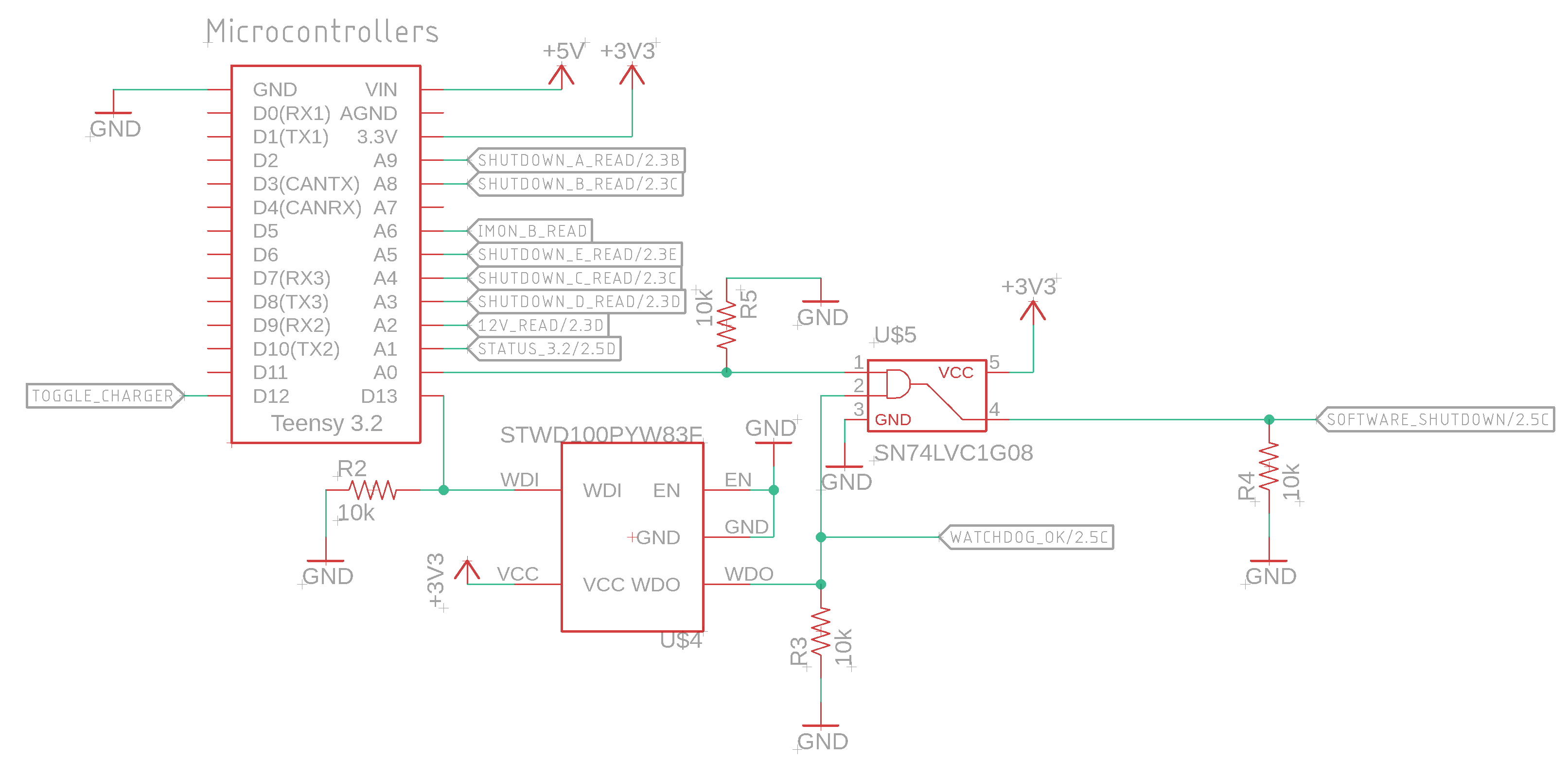
Figure 4. Schematic showing the watchdog circuit in place to catch microcontroller faults.
The final safety mechanism incorporated on this board is a watchdog timer to ensure the Teensy 3.2 is operating properly. The watchdog timer requires a signal from the Teensy and if that signal is not received, the watchdog timer will trip the shutdown circuit, once again turning off the charger. This system is in place to catch anytime the Teensy freezes, stops, or crashes to ensure a safe shutdown of the charger.
The board has been designed with many redundancies to ensure charging occurs safely and consistently. If one system fails, another system will always catch that failure before any damage or safety is compromised. This allows our team to be efficient yet confident while charging our car's battery pack.
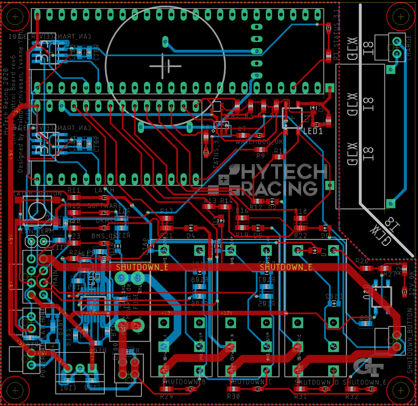
III. Final Steps
Once we finished designing our board, we had to get them manufactured. To manufacture your own PCBs, you can use JLCPCB, at https://jlcpcb.com/RAT. Just hit “QUOTE NOW” to order your custom PCB. Our team chooses JLCPCB because of the high quality for the price along with timely manufacturing.

Figure 5. Charger Controller PCB arrived in shop after manufacturing by JLCPCB.
Discussions
Become a Hackaday.io Member
Create an account to leave a comment. Already have an account? Log In.