 Ken Yap
I picked up the book 300 Circuits by Elektor Publishers from my shelf today. The title page showed that I had acquired it 22 Nov 1982 and it was the second edition. As the first edition was published in 1979, this makes the circuits more than 40 years old. I think the designs give good insight into how much electronics has advanced over the decades. So I've decided to pick 10 circuits from it at random to comment on. The last one is a favourite of mine.
Most of the time I won't show the circuits, I will just describe them. Very little is lost this way.
First let's generate 9 random numbers between 1 and 300 inclusive. The 10th is selected by me.
$ for i in {1..9}; do echo -n "$((RANDOM%300+1)) "; done; echo
199 146 73 220 233 259 4 50 83
Sharp readers will note that because $RANDOM ranges from 0 to 32767, the first 68 circuits have a larger chance of being selected, but not by much. So let's go to the selection.
199 Cascode current source
This circuit uses a transistor whose base is fed from a voltage reference of two Si diodes in series. The constant current is then 0.6/R where R is the emitter resistor. An improved version uses a second transistor in series with the first one's collector to improve the constancy w.r.t. supply voltage. I'll show the second circuit to make things clear.
This is still a useful technique although more likely to appear as part of a larger design. Or you can get a constant current IC off the shelf.
146 Division by 7
This showed how to get a TTL 7490 (anybody remember this?) to divide by 7. The trick is because 7 contains three 1's and the reset to 0 gate has only 2 inputs, you don't reset to 0, but reset to 9 on 6. Thus the sequence is 0 1 2 3 4 5 9 0 ...
73 Dark room aid
This meter circuit used a LDR to measure the brightness of the image projected by the enlarger to indicate the exposure needed. Does anybody still remember dark rooms, enlargers, photo paper, chemicals, the lot? I used to have a commercially sold meter embodying this idea. You swung a diffusing filter over the enlarger lens to average the image brightness and then by turning meter's dial until a neon lamp (no cheap LEDs then) lit, you could read off the seconds of exposure needed. I'm also certain it had to be calibrated for each batch of photo paper.
220 Blown fuse indicator
This is quite a simple idea. A neon lamp, with rectifier diode, smoothing capacitor and limiting resistor, are put across a fuse. When the fuse goes open circuit, the voltage across it is sufficient to make the lamp light.
These days unlicensed people aren't allowed to mess with mains wiring, so one can't actually put this idea into the field.
233 Triangle generator
This uses an op-amp to generate a triangular waveform. The sort of thing you learn in a course on using op-amps.
259 Triac control
This is a standard diac/triac circuit for controlling a load connected to the mains, such as a lamp. They worked with incandescent lamps, not with (compact) fluorescent lamps, and I don't know about LED lighting. In any case the rage these days is to control the LED lighting, including colour, through a network connection. That shows how much more efficient and cheaper LEDs have become over the years.
4 LED dimmer
This circuit provides a variable voltage to vary the brightness of LED displays. Nowadays you would do it by PWM in the microcontroller driving the LEDs.
50 Audioscope
This circuit allowed an audio signal to be displayed on a TV screen. These days you could probably find a computer program reading a sound card, or a phone app, to analyse every aspect of an audio signal.
83 Car headlight alarm
This is intended to remind a motorist who forgets to switch off the headlight when leaving the car. After a time delay provided by a monostable, an alarm sounds. There is a 7-segment display but that just displays L. Nowadays cars do this automatically after you have locked the door giving you a few seconds of illumination to find your doorstep or whatever.
Before we go on to the last circuit, I want to remark on how many ideas were to extend existing digital gates using diodes or extra transistors. Those were the days when ICs were relatively expensive. Nowadays one wouldn't hesitate to use the appropriate IC, or the function has been subsumed into firmware.
... and finally
Elektor periodically published joke circuits which people who could read circuits would understand. This is one of my favourites.
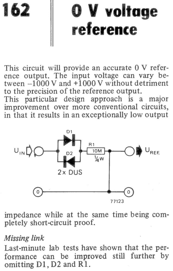
DUS means Diode Universal Silicon by the way. In other words, a generic device like a 1N4148. You might argue that you should use a 1N4007 because of the input voltage range, but as the Missing link note states, it really doesn't matter. 🤣
Discussions
Become a Hackaday.io Member
Create an account to leave a comment. Already have an account? Log In.