 Dan O'Shea
Wifi-Telnet-FPGA-NTSC Drunk Wall Clock!
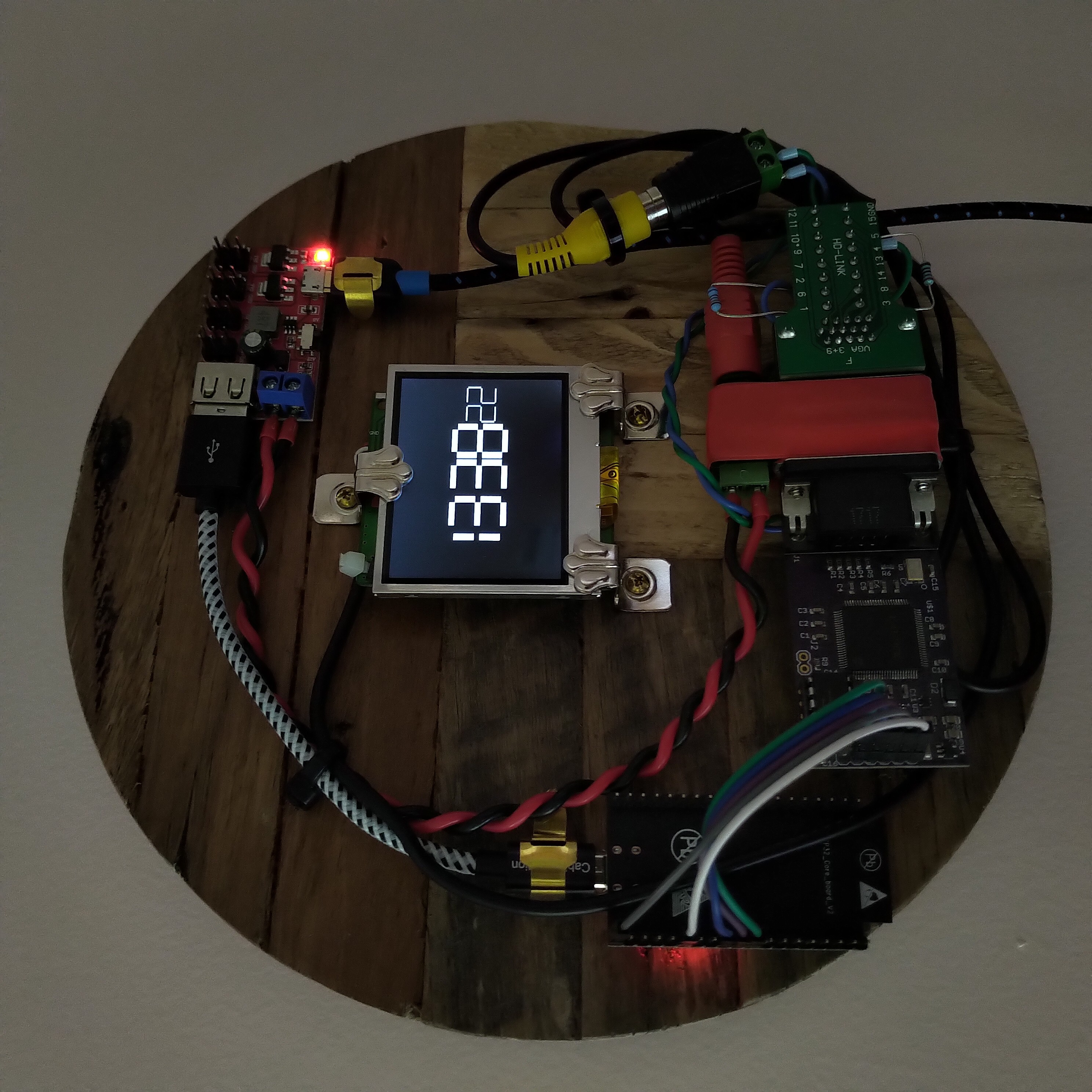
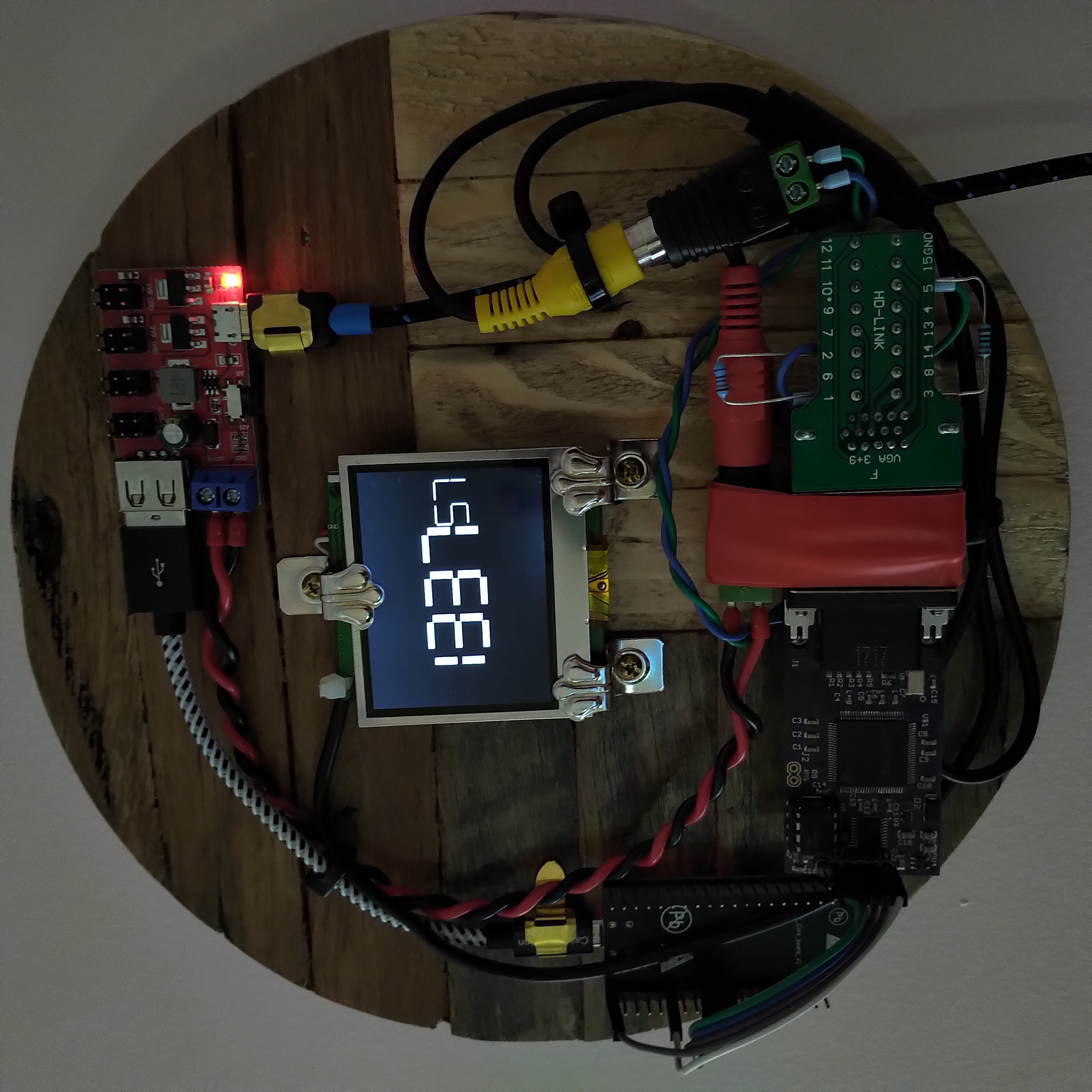
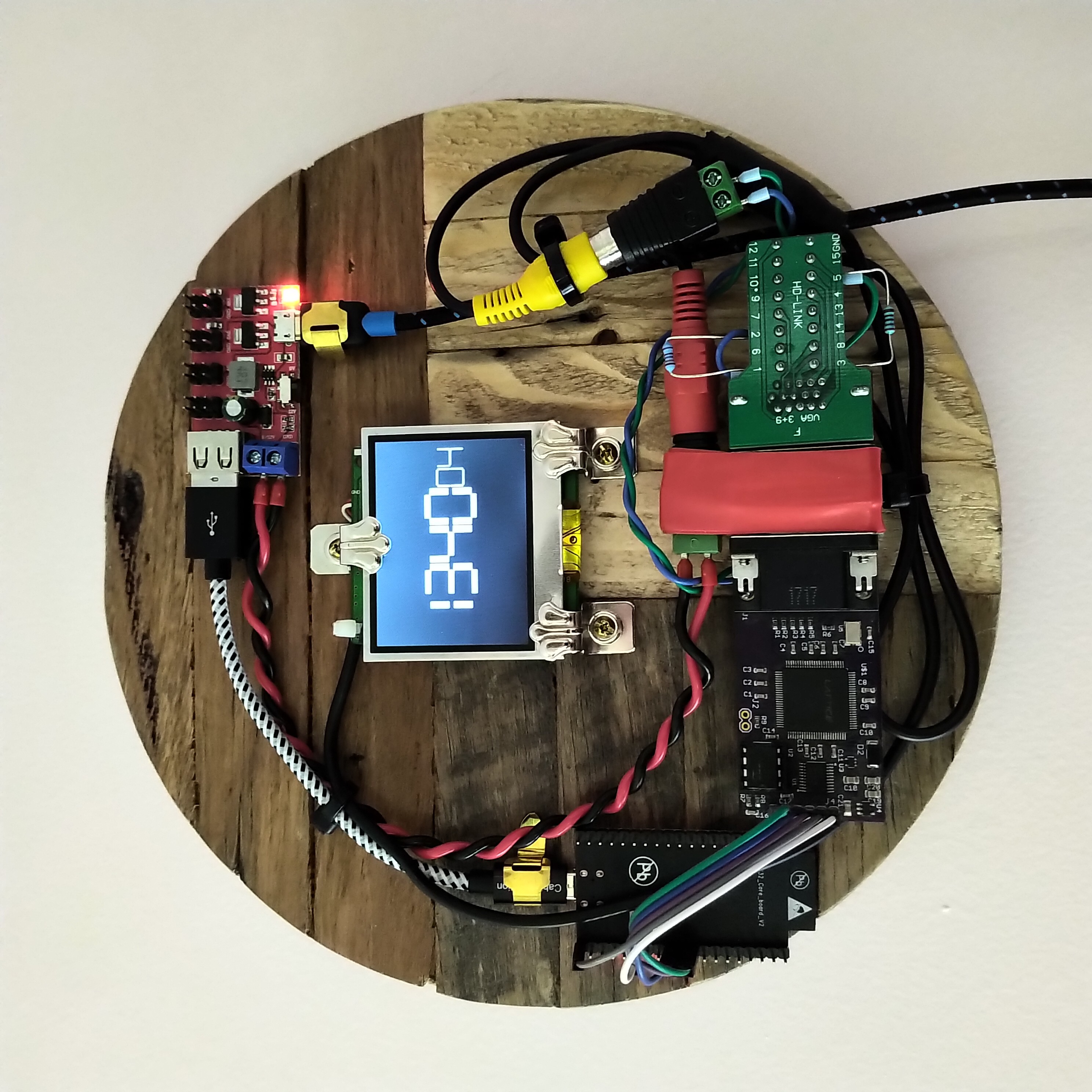
Using an ESP32 (DevKitC V2) to open a Telnet connection over the local network to an old Raspberry Pi One (Model B Rev 2), and repeatedly sending the Linux 'date' command to get the current time - then shifting out the digits returned to one of my old VGA1306 FPGA boards, which then uses a few external resistors on a VGA breakout board as an R2R DAC to output 7-segment digits as black-and-white NTSC composite video (not VGA) to the guts of an old 2.5" RCA Video TFT LCD! 😅
The inherent laggyness of this scheme is visible in the seconds counter on the clock - not a neat and precise march from zero to fifty-nine seconds, but more of a lurching stumbling drunken progression from minute to minute - and I love it! Obviously there are more precise ways of keeping time, but that was not the goal. This is art. This clock has a personality. This object is pure hack.
For the code on the ESP32 I used Arduino's default WiFiClientBasic.ino sketch as a skeleton to get a network connection, and also took inspiration from martydill's telnet code, to step through the following sequence:
1. connect ESP32 to wifi
2. connect ESP32 to raspberrypi host
3. respond appropriately to telnet protocol negotiations from the pi
4. wait for colon characters and automate sending the username and password, to login to the pi
5. wait for dollar sign character at the end of each command prompt and send "date +%t%H%M%S"
6. wait for the tab character returned with the output of the Linux 'date' command
7. read in the 6 digits of the time, HHMMSS (need to subtract 48 from the ASCII character values)
8. step through sending each pair of digits to the FPGA, packed as two 4-bit nibbles in a single byte
(total of 3 bytes = 24 bits shifted out, max digit value is 9 (1001 in binary) so only need 4 bits to represent)
9. return to step 5
The VGA1306 FPGA logic uses each 4-bit value in the 24-bit register to assemble the seven segments of each digit on the screen. I originally designed the board to output 8-colour VGA, not composite video - so my hacky method of using it to generate black-and-white NTSC composite video was to use the three separate RGB signals combined to represent a single 3-bit digital-to-analog voltage value instead. There are already 270Ω resistors built-in on the Red / Green / Blue VGA output pins, so these are being repurposed as half of the 3-bit R2R DAC to get the necessary voltage levels for composite video (the remaining three external resistors in the DAC are on the VGA breakout board).
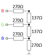
This got me close enough to the 0V / 0.3V / 1V values needed. Everything on the drunk wall clock is powered from a neat little 1.8V / 3.3V / 5V / 9V / 12V Power Breakout Board.
All of the code is on GitHub here (plus the Excel spreadsheet I used to layout the pixels for each digit).
I bought the lovely 'reclaimed-wood' base from this Etsy artist. The VGA1306 board was being produced by kitsch-bent a few years back, but CraftsbyDad has also been making some lately and selling them at-cost on Tindie.
But wait, there's more - the Raspberry Pi running the 'date' commands is also itself acting as a wall clock, using an Adafruit PiTFT shield and running tty-clock!
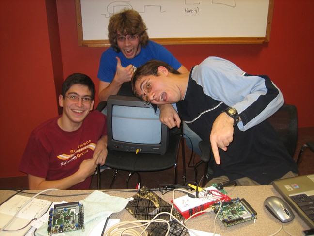
Last, but far from least, many thanks to these three guys down here for writing the NTSC Verilog code back in 2007! 😊
Discussions
Become a Hackaday.io Member
Create an account to leave a comment. Already have an account? Log In.