Introduction
In Formula student competition you have to be as fast as possible to have a chance to compete with other teams. Knowing how fast your lap times are, is a competitive advantage. In Aristurtle, we managed to keep track of lap times in an automated and innovative way. The system in its simplest form, can be divided into a receiver and a transmitter. In the transmitter side an ultrasonic sensor is used for the detection of the car. The working principle of the sensor is based on longitudinal sound waves and the reflection phenomenon. Each time the sensor detects the car, the transmitter automatically sends that information wirelessly to the receiver. The lap time, the unknown of the equation, is being calculated on the receiver side. The receiver solves the equation by calculating the time between the messages he received.
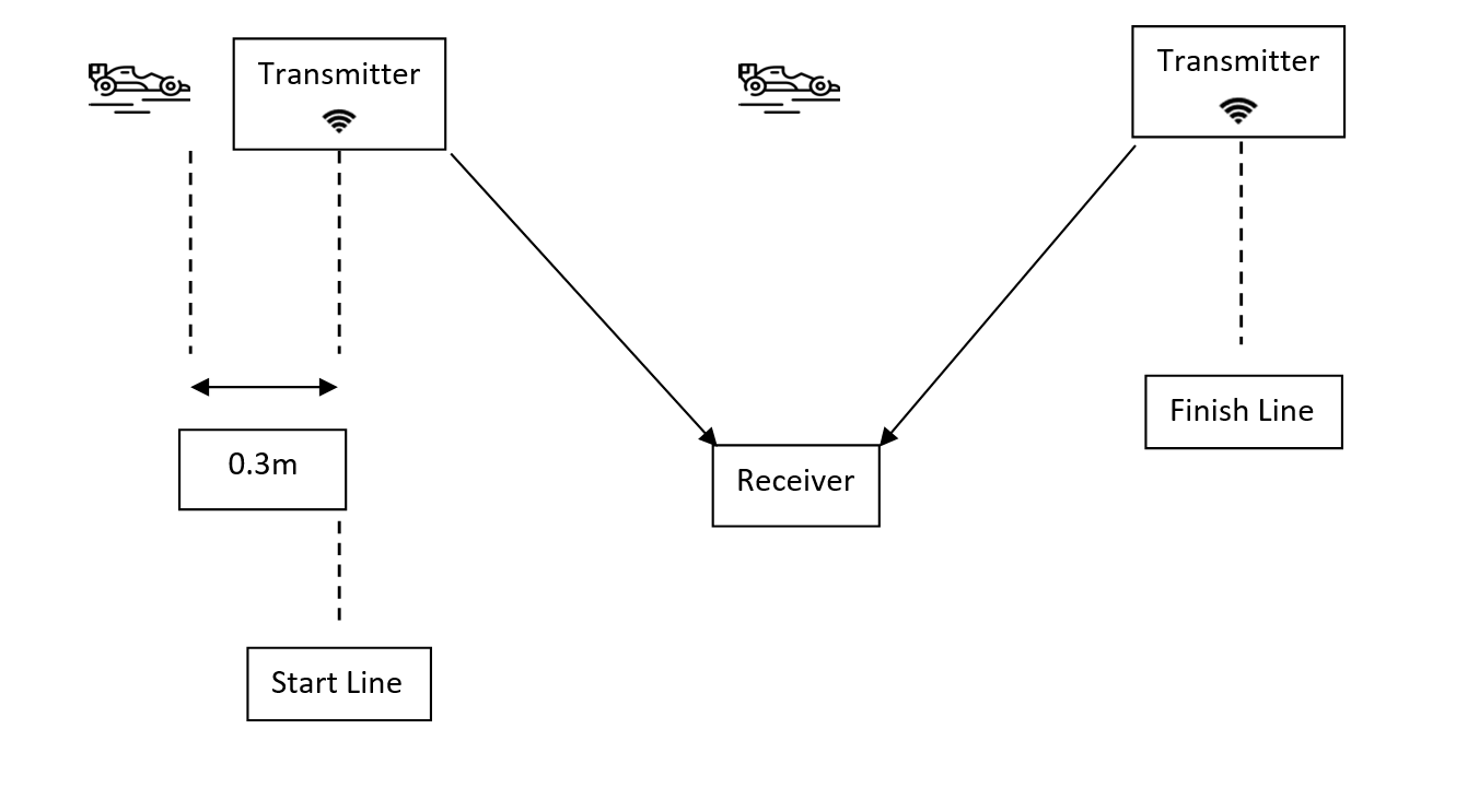
Timekeeping Architecture
The system was tested with success in all kinds of dynamic events that FSAE organizes. For example, for the acceleration event we came up with the following architecture.
Hardware
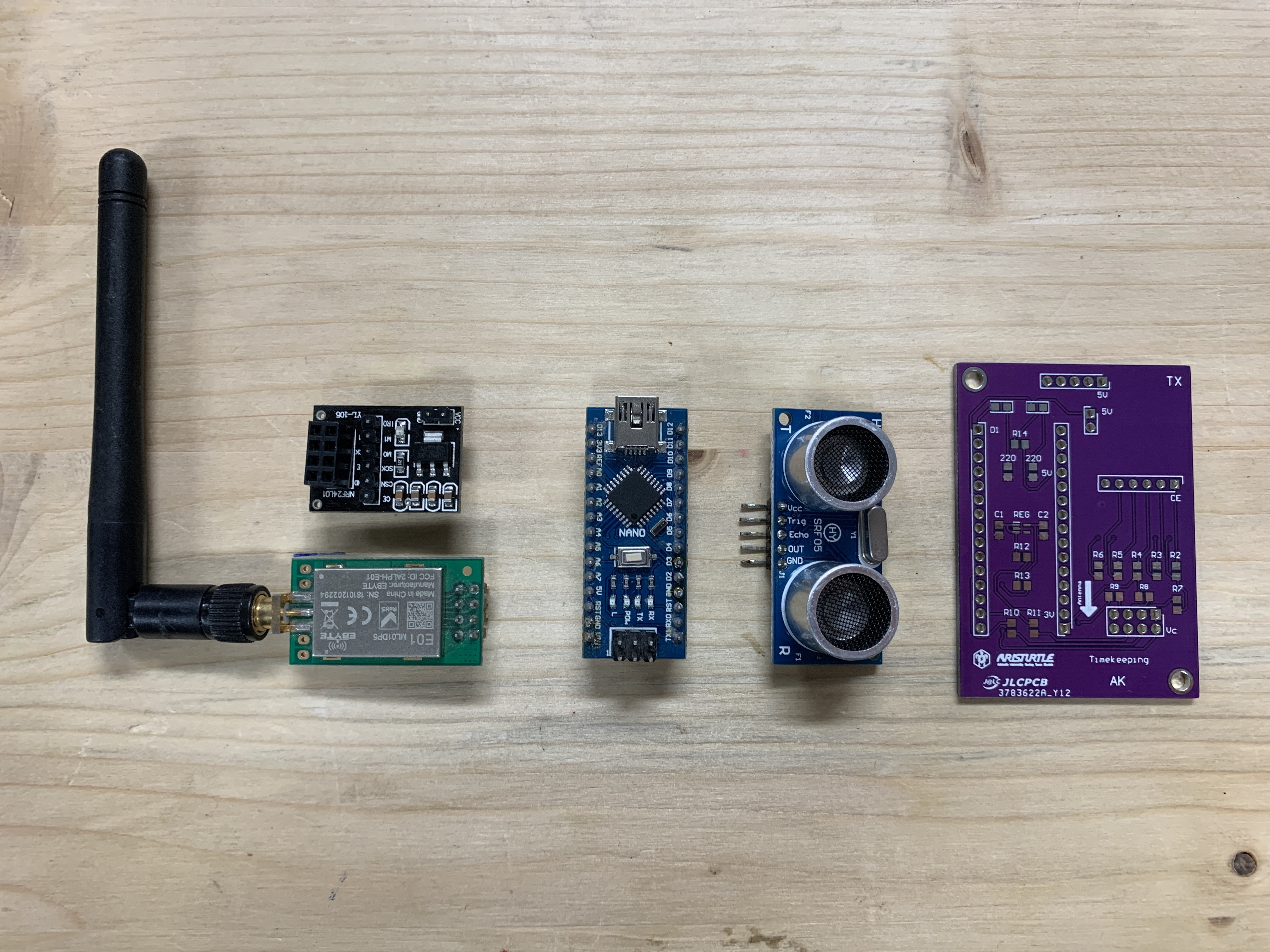
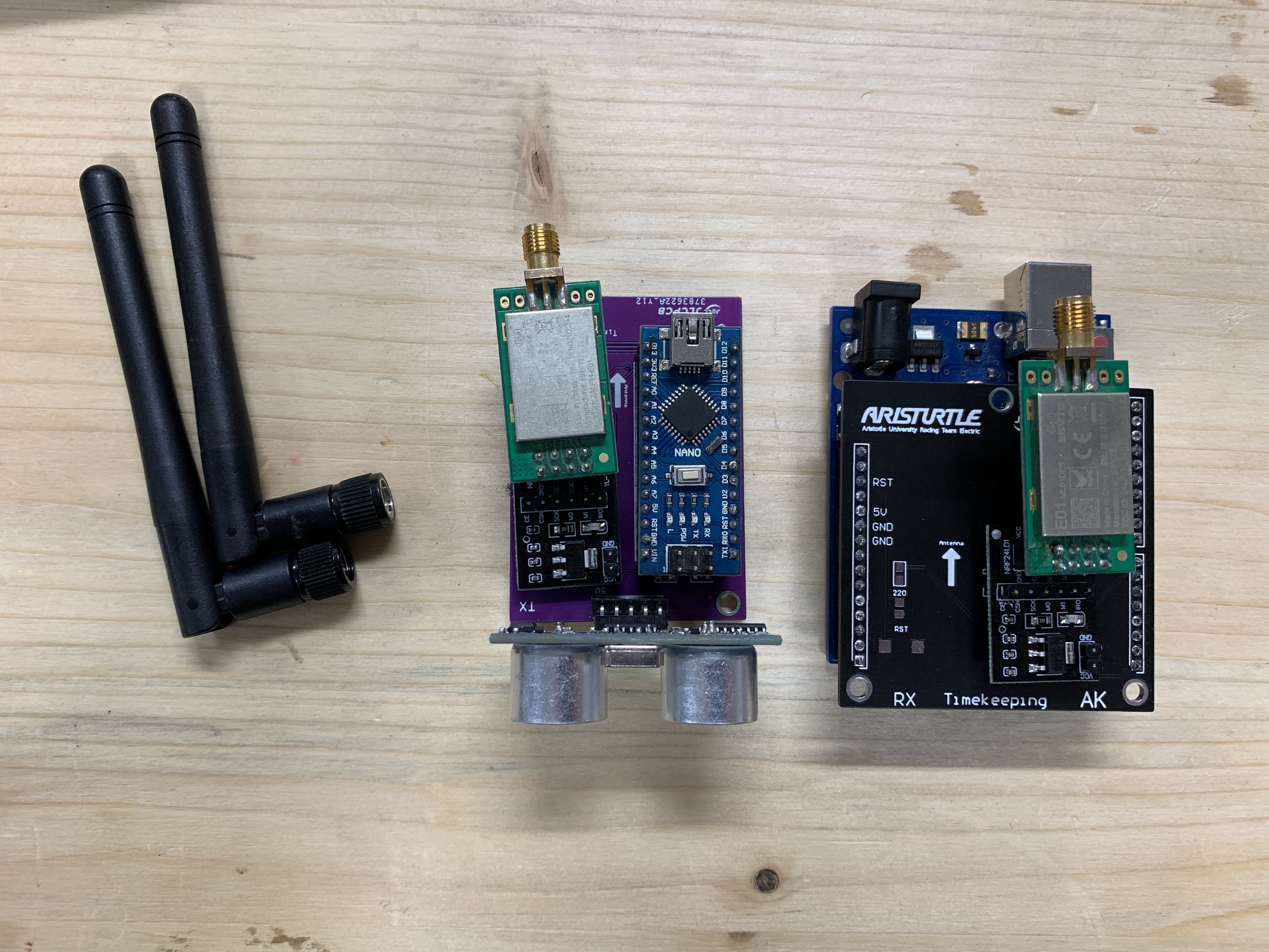
The transmitter subsystem consists of :
1 x Ultrasonic Sensor HC-SR05
1 x Arduino NANO
1 x nRF24L01 base module
1 x E01-ML01DP5 V6.5
Power Supply : power bank of 6700mAh
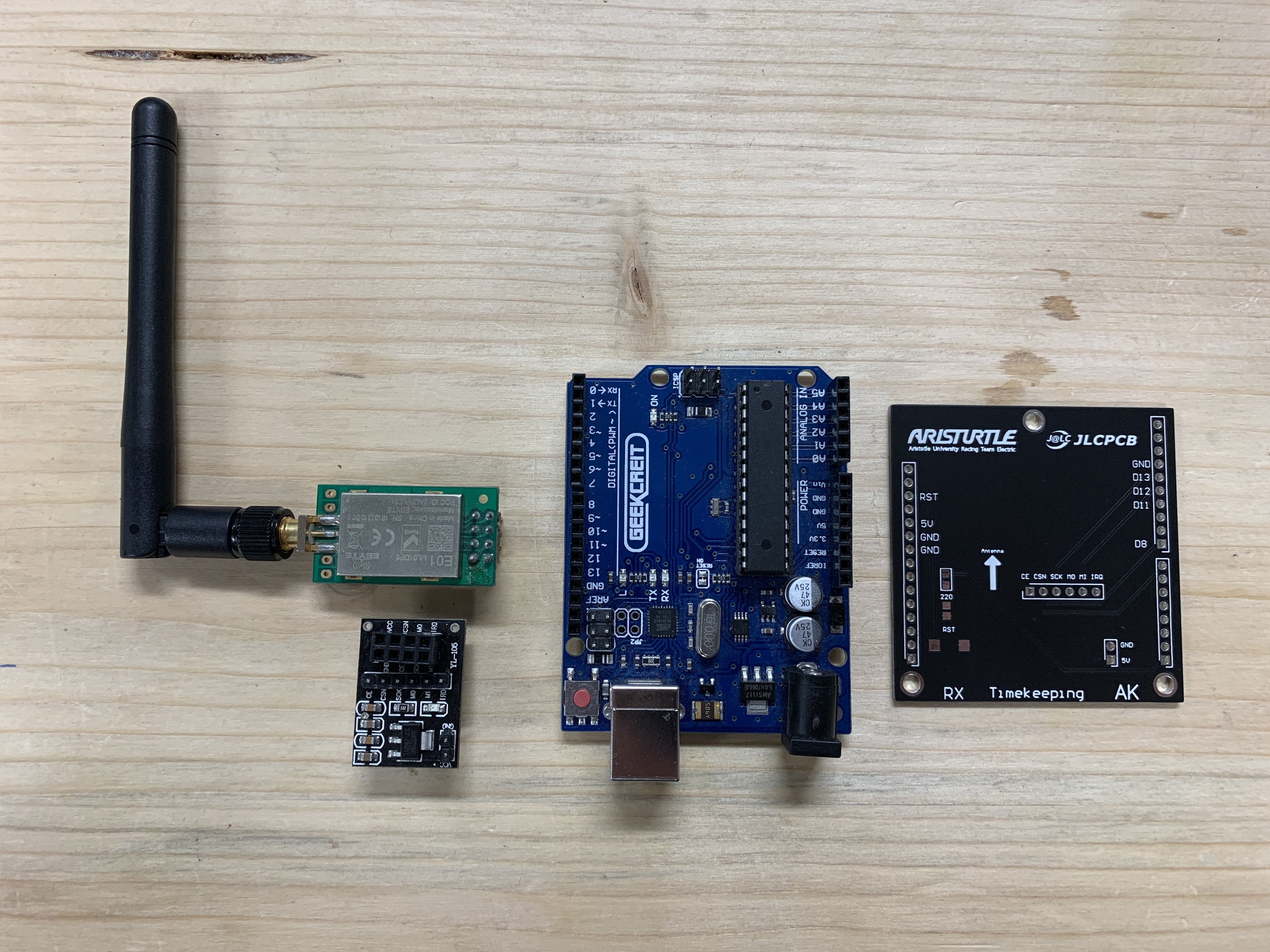
The receiver subsystem consists of :
1 x nRF24L01 base module
1 x E01-ML01DP5 V6.5
1 x Arduino UNO
Power Supply : From PC through USB
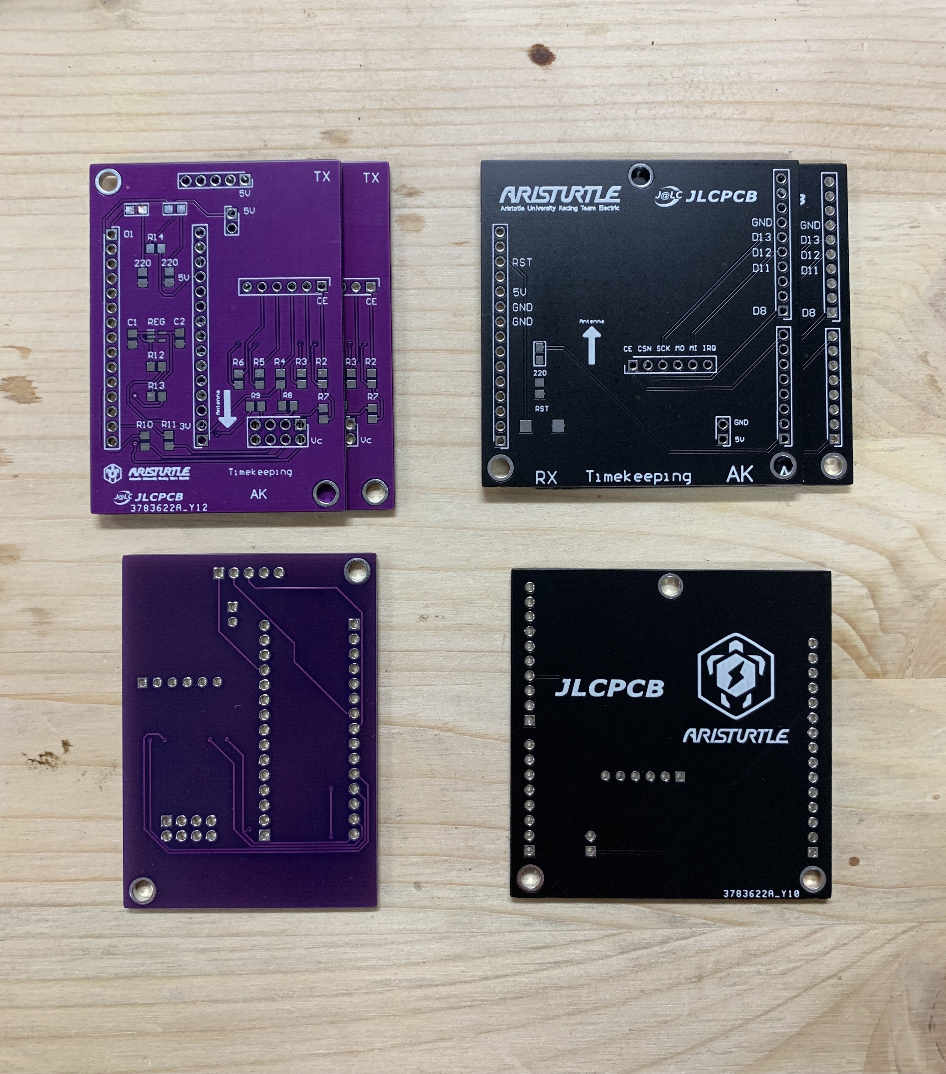
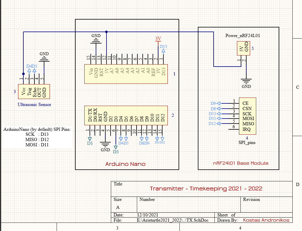
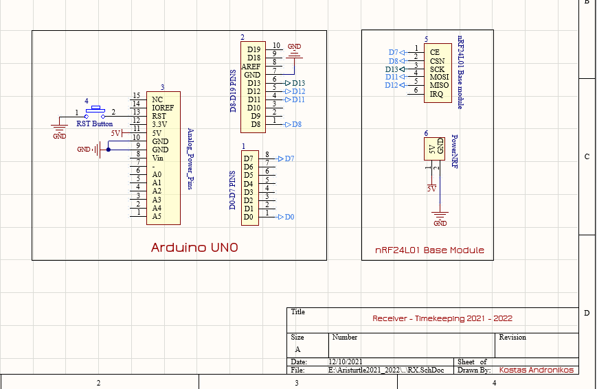
Schematic Designs
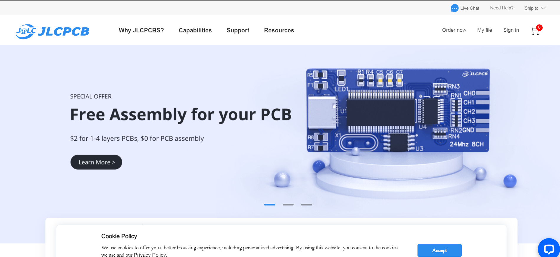
How to order PCBs from JLCPCB
Here, we would like to take this opportunity to express our gratitude towards JLCPCB for providing the PCBs and making this project a reality. You can order your own PCBs from JLCPCB by clicking here . First of all, you have to add a gerber file. Gerber file is a file that is exported from the software that you design the PCB. In our case that software is Altium Designer. The next step is to select all the characteristics you require for your PCB. After that, you will have to add the remaining files, such as the bom files and the pick and place files. Upload these files and you are ready to complete the order.
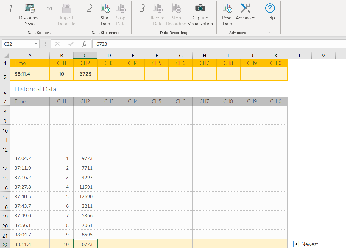
Timekeeping Interface
The serial data from the USB is being transferred automatically to an excel that is being updated in real time. To do that we used Data Streamer and you can find it here .
Receiver Skidpad Code
#include <SPI.h>
#include <nRF24L01.h>
#include <RF24.h>
#include <RF24_config.h>
#include <stdio.h>
#include "printf.h"
#include <RF24Network.h>

// Power Amplifier available levels Levels : RF24_PA_MIN (-18dBm), RF24_PA_LOW(-12dBm), RF24_PA_HIGH(-6dBm) AND RF24_PA_MAX(0dBm)
#define PA_LEVEL RF24_PA_MAX // FIND 100 uF between VCC and GND
// Available Data Rates : RF24_250KBPS for 250kbs, RF24_1MBPS for 1Mbps, or RF24_2MBPS for 2Mbps . Choosing 250kbs we get the longest range.
#define DataRate RF24_250KBPS

// Create a RF24 object
RF24 radio(7, 8);  // CE, CSN
RF24Network network(radio);
const uint16_t this_node = 00 ;

// Timekeeping with millis()
unsigned long StartTime, CurrentTime, ElapsedTime = 0   ;

uint8_t data ;
int counter, lap, j = 0;
// Counter is a variable which gives me the ability to seperate the messages so I can measure the elapsed time between them.

void setup()
{

// --- Serial communication Start ---

  SPI.begin();
  Serial.begin(9600);


// --- Serial communication End ---

// --- NRF Configuration Start ---

  radio.begin();
  network.begin(90, this_node);  // (channel, node address)
  radio.enableDynamicPayloads();

  radio.setDataRate(DataRate);
  radio.setPALevel(PA_LEVEL);
  // radio.setPayloadSize();

  radio.setAutoAck(true); // Checksum Logic...In the end of each packet there is the CRC number (1-2 byte). Due to the fact that the receiver knows
                          // how to calculate the CRC, he can inform the sender if the message was correct or not.
                          // If the CRC is correct, receiver send an ACK message to the sender, and basically tells him to continue to send
                          // the next packet of data. If the receiver does not send the ACK message, the sender must send the packet again.


  radio.enableDynamicPayloads();    // Must have for multi pipe receiving

  printf_begin();
  radio.printDetails(); // don't printDetails in excel...It works properly only in Serial Monitor.

  radio.startListening();           // Put this module in receiver mode.


// --- NRF Configuration End ---

}

void loop()
{
  network.update();
  while (network.available())
  {
    RF24NetworkHeader header;
    network.read(header, &data, sizeof(data)); // Read the incoming data
    counter++ ;
    if(counter == 1)
    {
      if(j == 0)
      {
         StartTime = starttime();
         lap++;
      }
      if (j > 0)
      {
        ElapsedTime = elapsedtime();
        Serial.print(lap);
        Serial.print(",");
        Serial.println(ElapsedTime);
        lap++;
      }
      j = 1 ;
    }
    if(counter == 2)
    {
      // Serial.print("First Lap Time: ");
      ElapsedTime = elapsedtime();
      // The following prints are in this way in order to read the data from excel ( with Data Streamer )
      Serial.print(lap);
      Serial.print(",");
      Serial.println(ElapsedTime);
      lap++;
      counter = 0 ;
    }
  }
}

unsigned long starttime()
{
  return millis();
}

unsigned long elapsedtime()
{
  CurrentTime = millis();
  ElapsedTime = CurrentTime - StartTime ;
  StartTime = CurrentTime ;
  return ElapsedTime ;
}
Transmitter Code
#include <SPI.h>
#include <nRF24L01.h>
#include <RF24.h>
#include <RF24_config.h>
#include <stdio.h>  // It doesn't work the printf without this!!!
#include "printf.h"
#include <NewPing.h>
#include <RF24Network.h>


// Power Amplifier available levels Levels : RF24_PA_MIN (-18dBm), RF24_PA_LOW(-12dBm), RF24_PA_HIGH(-6dBm) AND RF24_PA_MAX(0dBm)
#define PA_LEVEL RF24_PA_MAX
// Available Data Rates : RF24_250KBPS for 250kbs, RF24_1MBPS for 1Mbps, or RF24_2MBPS for 2Mbps . Choosing 250kbs we get the longest range.
#define DataRate RF24_250KBPS
#define CE_Pin 9
#define CSN_Pin 8

// Configuration of Ultrasonic sensor :
#define PinToEcho 5 // Attach D5 of Arduino Nano to echo pin of Ultrasonic sensor
#define PinToTrig 4 // Attach D4 of Arduino Nano to trig pin of Ultrasonic sensor
#define MAX_Distance 250
NewPing ultrasonic(PinToTrig, PinToEcho, MAX_Distance);
int distance = 0 ; // for Serial print purposes


// Variable that indicates if the car has passed or not
uint8_t passed = 0 ;

// create an RF24 object
RF24 radio(CE_Pin, CSN_Pin);
RF24Network network(radio) ;
const uint16_t this_node = 01 ;    // Address of our node in Octal format.
const uint16_t master00  = 00 ;    // Address of the other node in Octal format

// LED
#define RES1 1 // For increasing power consumption in order the powerbank not to get into sleep mode.
#define RES2 3 //

void setup()
{

  SPI.begin();
  Serial.begin(115200);
  // --- NRF Configuration Start ---

  radio.begin();
  network.begin(90, this_node);

  radio.setDataRate(DataRate);
  radio.setPALevel(PA_LEVEL);
  radio.enableDynamicPayloads();

  printf_begin();
  radio.printDetails();

  radio.stopListening();

  // --- NRF Configuration End ---
  pinMode(RES1,OUTPUT);
  pinMode(RES2,OUTPUT);
}


void loop()
{
  digitalWrite(RES1, HIGH);
  digitalWrite(RES2, HIGH);
  network.update();
  passed = checkIfPassed();
  if(passed)
  {
     RF24NetworkHeader header1(master00); // send to master node.
     network.write(header1, &passed, sizeof(passed));
     delay(2000);
  }
}
uint8_t checkIfPassed()
{
  passed = 0 ;
  unsigned int uS = ultrasonic.ping();  // Send ping, get ping time in microseconds (uS).
  distance = ultrasonic.convert_cm(uS);

  if (distance > 1 && distance < 200)
  {
    Serial.print("Distance: ");
    Serial.print(distance);    // Convert ping time to distance and print result (0 = outside set distance range, no ping echo)
    Serial.print(" cm , passed: ");
    passed = 1 ;
    Serial.println(passed);
  }

  return passed ;
}
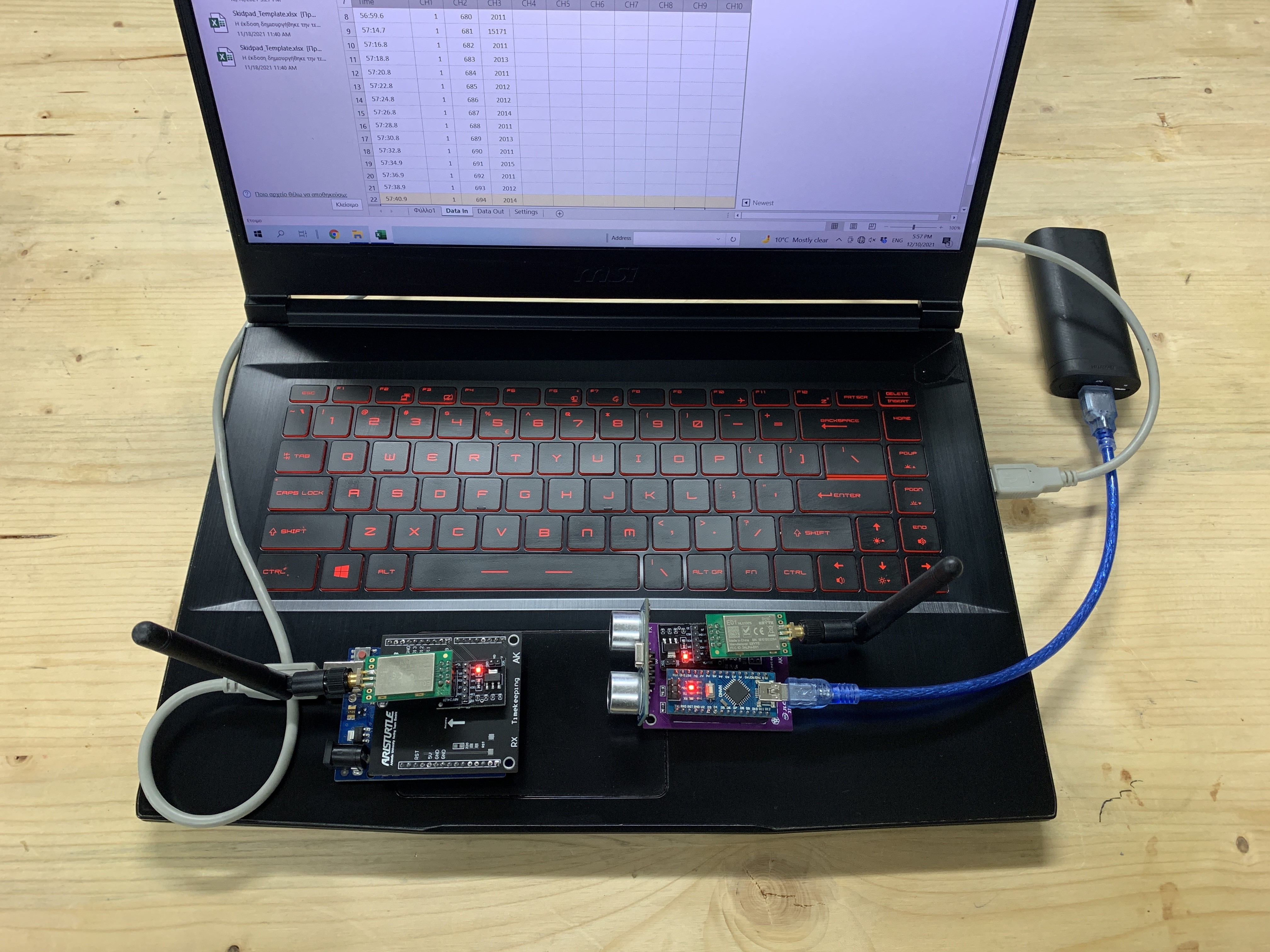
Proof of concept
We tested the system with the receiver on the left and the transmitter on the right. Note that this set up is suitable for keeping the time for the Skidpad Event. We also found that the maximum distance that these modules have is around 400m in line of sight (LoS) by sending 1 byte/s.
Discussions
Become a Hackaday.io Member
Create an account to leave a comment. Already have an account? Log In.