-
Telemetry
02/10/2023 at 07:35 • 0 commentsIntroduction
As our team is competing in Formula Student competitions, it is vital for us to know the state of the vehicle every single time while on track. Not knowing critical parameters like cell voltages and temperatures may result to severe problems that bring both safety and performance at risk. Thus, as a team we have implemented a wireless communication Telemetry system based on LoRa (Long Range) communication protocol to ensure that we monitor all those critical parameters live. By choosing this protocol we can achieve lots of information being sent on a distance over 500 meters.
Step 1: Telemetry architecture
![]()
The system consists of one transmitter and one receiver. The transmitter is mounted on the car and is connected to the car’s CAN channels. It is responsible for collecting all the data from the car and for transmitting them wirelessly to the receiver which is connected to the user’s laptop. Then, the data are being transferred through serial communication to a self-developed Telemetry interface that visualizes them in a proper manner.
Step 2: Hardware
The transmitter subsystem consists of:
- 1 × STM32F446RE
- 1 × 2.5dBi Panel mount passive antenna
- 1 × LoRa 868MHz chip
- Power Supply: 24V through battery cells or Power Supply Unit
- 1 × STM32F446RE Nucleo board
- 1 × 2.5dBi Panel mount passive antenna
- 1 × LoRa 868MHz chip
- Power Supply: From PC through USB
The receiver subsystem consists of:
- 1 × STM32F446RE Nucleo board
- 1 × 2.5dBi Panel mount passive antenna
- 1 × LoRa 868MHz chip
- Power Supply: From PC through USB
Step 3: Schematic Designs
Transmitter schematic:
![]()
Receiver schematic:
![]()
Step 4: How to Order PCBs From JLCPCB
![]()
Here, we would like to take this opportunity to express our gratitude towards JLCPCB for providing the PCBs and making this project a reality. You can order your own PCBs from JLCPCB by clicking
on the following link: https://jlcpcb.com/HAR. First of all, you have to add a Gerber file. Gerber file is a file that is exported from the software that you design the PCB. In our case that software is Altium Designer. The next step is to select all the characteristics you require for your PCB. After that, you will have to add the remaining files, such as the BOM files and the pick and place files. Upload these files and you are ready to complete the order.
Step 5: Interface
![]()
All the data that are transmitted, are visualized in a informative and comprehensive self-developed interface using PyQt libraries. Note that all the variables have been downsampled because in an interface we don’t need that much refresh speed as this will only be seen by a human’s eye.
Step 6: Proof of concept
![]()
We have tested the system on track and validated that the transmitted payload is large enough (250 bytes) to cover all the variables that we need to monitor as well as that the maximum distance reaches approximately 500m in line of sight (LoS) making the choice of the communication protocol a suitable choice for robust long range data transmission.
-
Timekeeping
12/13/2021 at 15:36 • 0 commentsIntroduction
In Formula student competition you have to be as fast as possible to have a chance to compete with other teams. Knowing how fast your lap times are, is a competitive advantage. In Aristurtle, we managed to keep track of lap times in an automated and innovative way. The system in its simplest form, can be divided into a receiver and a transmitter. In the transmitter side an ultrasonic sensor is used for the detection of the car. The working principle of the sensor is based on longitudinal sound waves and the reflection phenomenon. Each time the sensor detects the car, the transmitter automatically sends that information wirelessly to the receiver. The lap time, the unknown of the equation, is being calculated on the receiver side. The receiver solves the equation by calculating the time between the messages he received.
Timekeeping Architecture
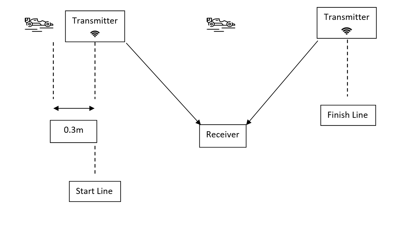
The system was tested with success in all kinds of dynamic events that FSAE organizes. For example, for the acceleration event we came up with the following architecture.
![]()
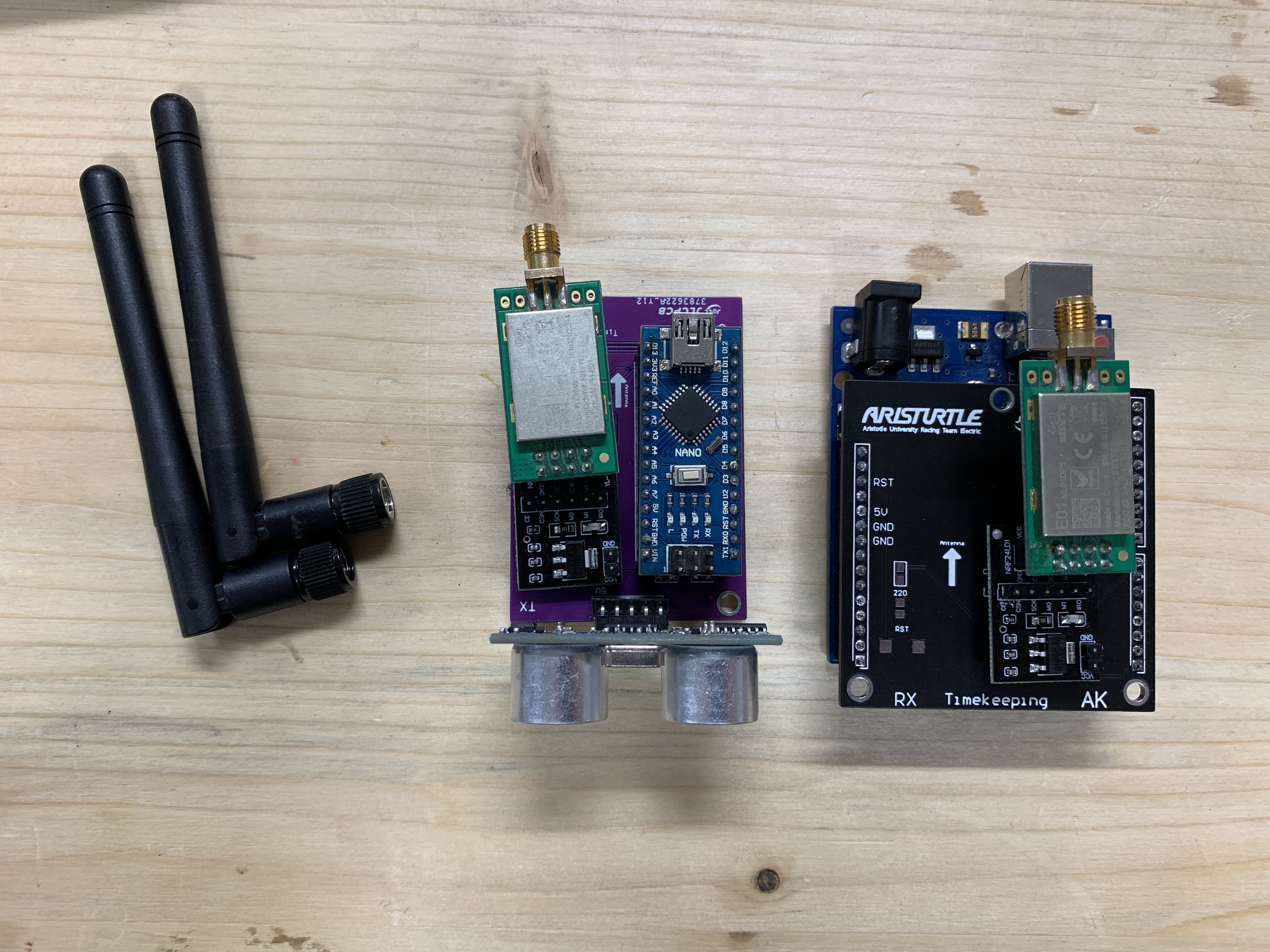
Hardware
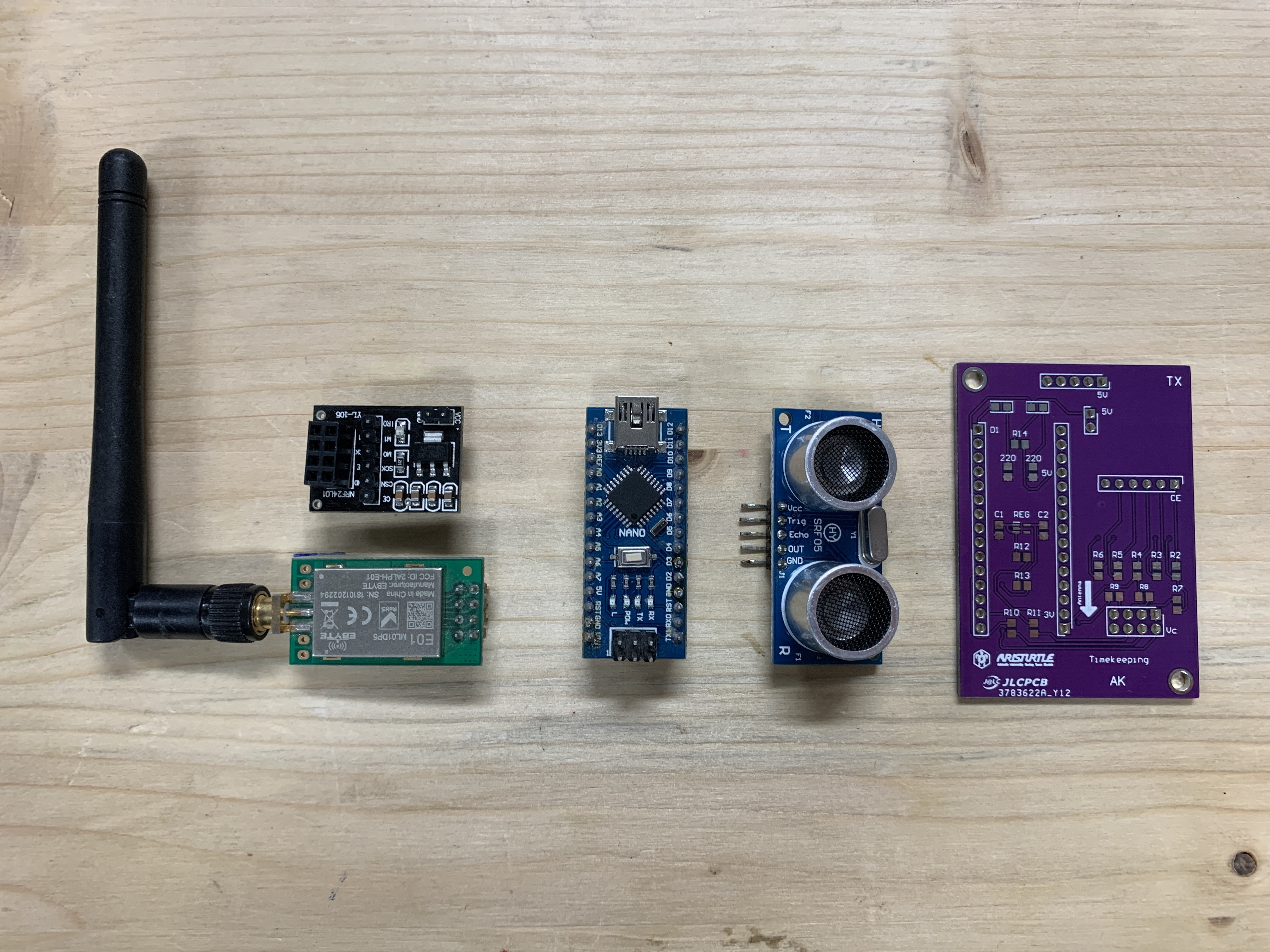
The transmitter subsystem consists of :
1 x Ultrasonic Sensor HC-SR05
1 x Arduino NANO
1 x nRF24L01 base module
1 x E01-ML01DP5 V6.5
Power Supply : power bank of 6700mAh
![]()
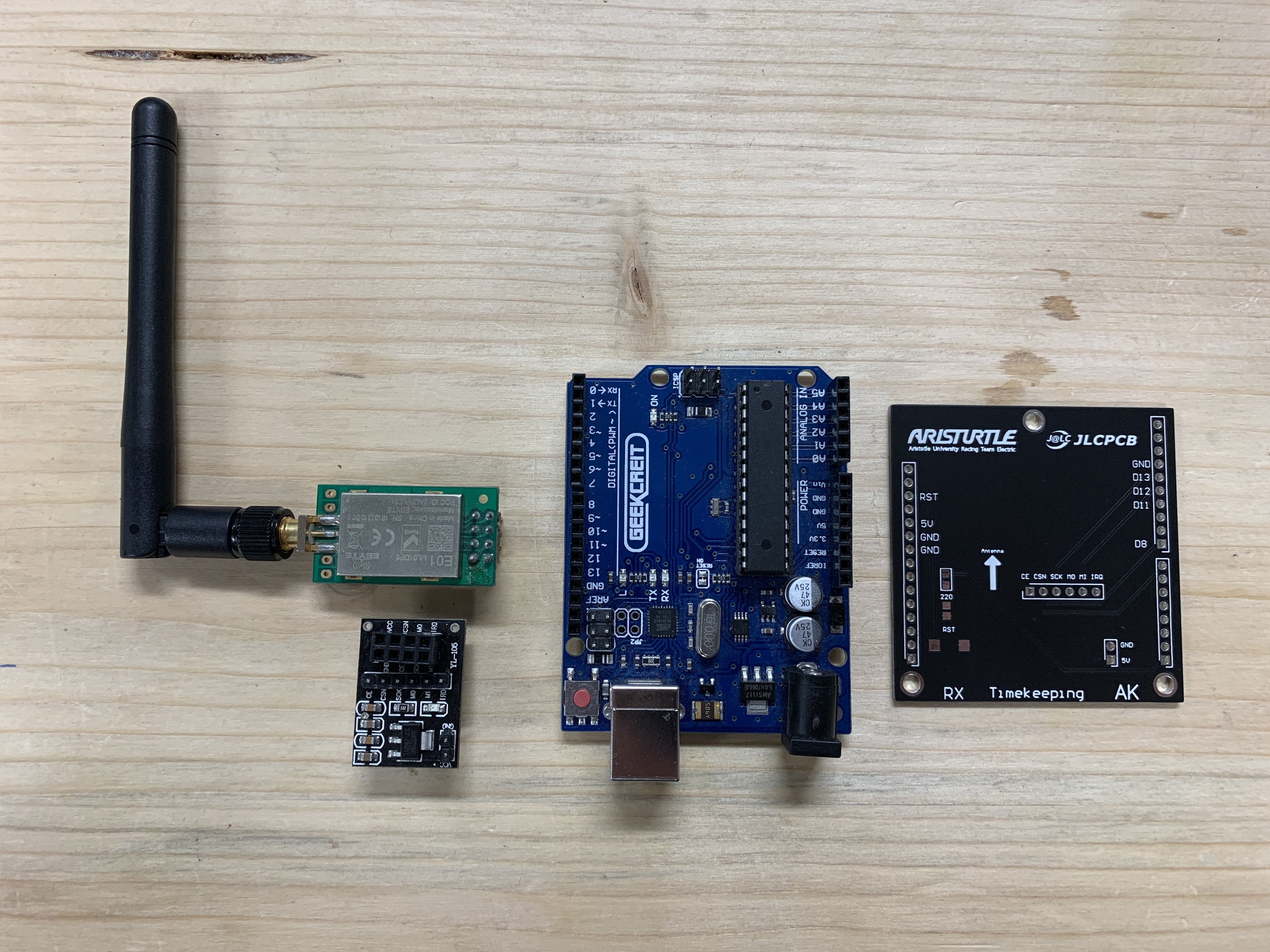
The receiver subsystem consists of :
1 x nRF24L01 base module
1 x E01-ML01DP5 V6.5
1 x Arduino UNO
Power Supply : From PC through USB
![]()
![]()
![]()
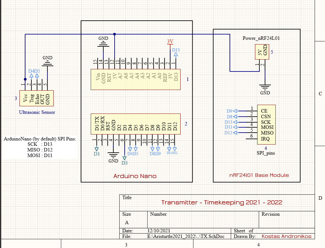
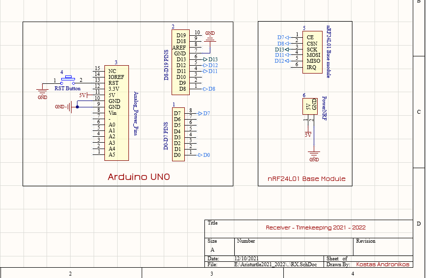
Schematic Designs
![]()
![]()
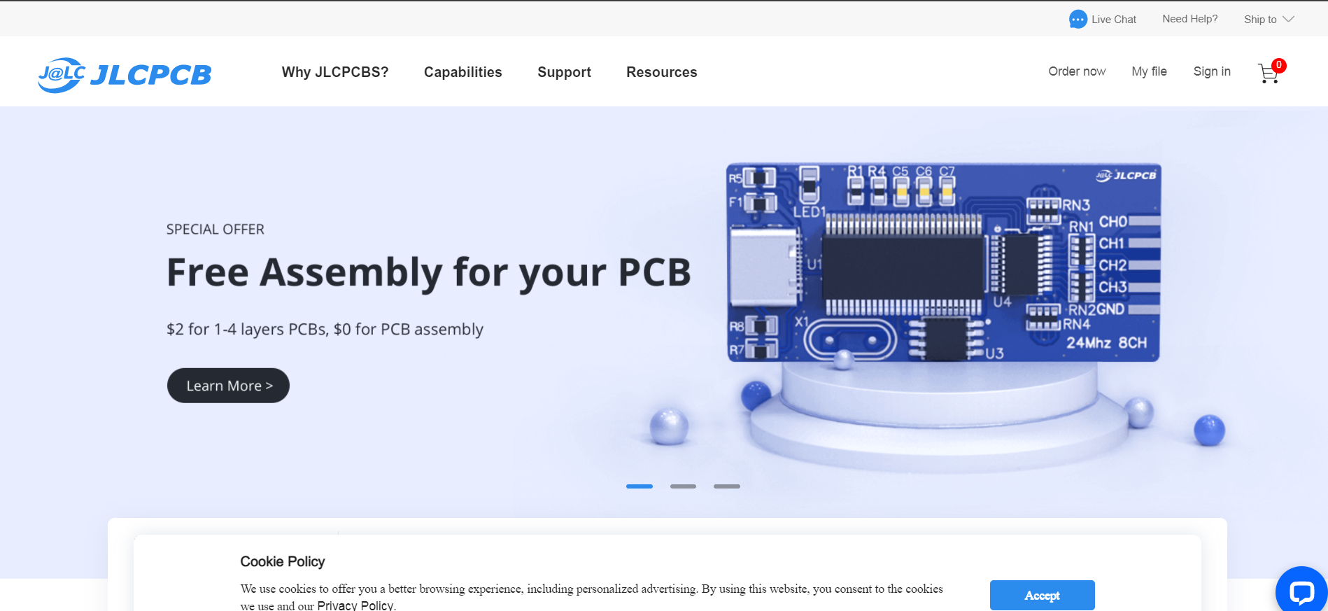
How to order PCBs from JLCPCB
Here, we would like to take this opportunity to express our gratitude towards JLCPCB for providing the PCBs and making this project a reality. You can order your own PCBs from JLCPCB by clicking here . First of all, you have to add a gerber file. Gerber file is a file that is exported from the software that you design the PCB. In our case that software is Altium Designer. The next step is to select all the characteristics you require for your PCB. After that, you will have to add the remaining files, such as the bom files and the pick and place files. Upload these files and you are ready to complete the order.
![]()
Timekeeping Interface
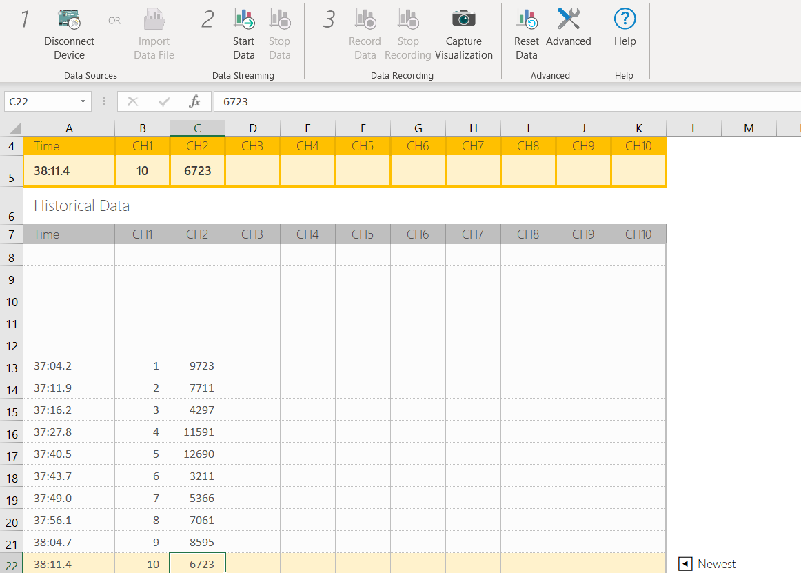
The serial data from the USB is being transferred automatically to an excel that is being updated in real time. To do that we used Data Streamer and you can find it here .
![]()
Receiver Skidpad Code
#include <SPI.h>
#include <nRF24L01.h>
#include <RF24.h>
#include <RF24_config.h>
#include <stdio.h>
#include "printf.h"
#include <RF24Network.h>

// Power Amplifier available levels Levels : RF24_PA_MIN (-18dBm), RF24_PA_LOW(-12dBm), RF24_PA_HIGH(-6dBm) AND RF24_PA_MAX(0dBm)
#define PA_LEVEL RF24_PA_MAX // FIND 100 uF between VCC and GND
// Available Data Rates : RF24_250KBPS for 250kbs, RF24_1MBPS for 1Mbps, or RF24_2MBPS for 2Mbps . Choosing...
Read more »
This user joined on 12/13/2021.


 Lutetium
 DTeel
DTeel John
John Dylan Bleier
 jareklupinski
 illumino
 Matthew Pearce
 Pierre Kil
 Tim Schonberger
 Andrew Peters