 Stefan-Xp
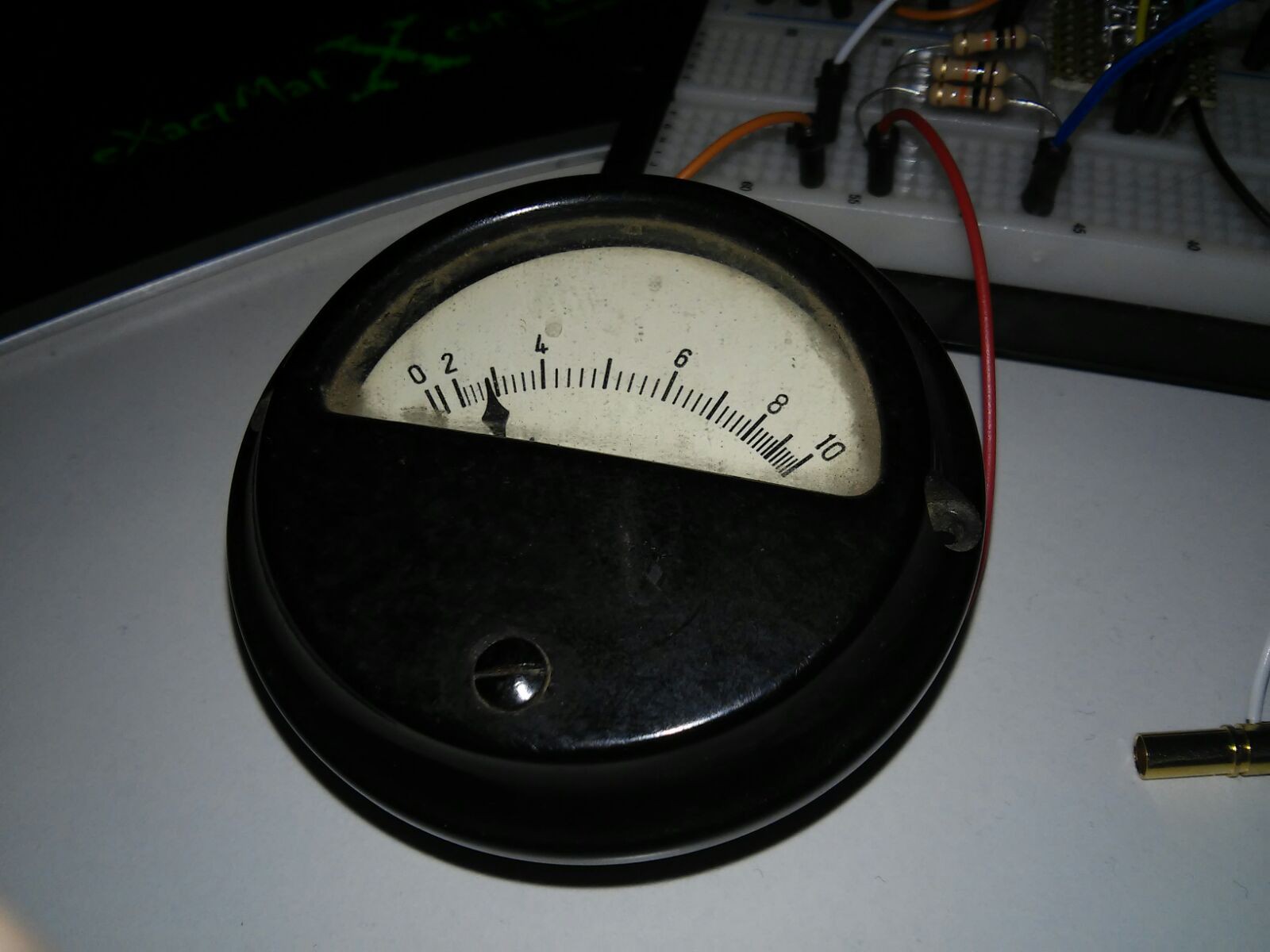
Finaly i had the mood and time to try one of the Analog Gauges. Please read more to find out more ;)
I created the following Arduino Code. Its not to difficult to read and awesomely short.
I just thought about Eliots Blog Post about State Machines and decided, that i have to sleep over it ;) (Even not sure if possible to use with Arduino...)
/*
 * Increasing and Decreasing Analog Gauge Value via PWM
 * Analog Gauge is attached to pin 9 in series with a ~ 3.3K resistor
 * Crted by Stefan-Xp
 */

const byte GaugePinNo = 9;              // Pin which the Gauge is connected to
const int GaugeDelayBetweenSteps = 50;  // Time Delay, which is taken between the Value changes
byte GaugeValue = 0;                    // Actual Gauge Value
byte State = 0;                         // Actual State: 0 = Count up, 1 = Count down

void setup() {
  // Set the Pin to Output
  pinMode(GaugePinNo, OUTPUT);

  // Initialise Serial Port
  Serial.begin(9600);
  Serial.println("Analoginstrument Test");
}

// This function writes the Value to the Output and prints the Value via Serial
byte write_Value (byte Value)
{
  // Set PWM Value
  analogWrite(GaugePinNo, Value);
  // Write Data on Serial Port
  Serial.print("Value: ");
  Serial.println(Value);

  // Select next State ...
  if (Value == 0)
    State = 0; // Value reached 0, so beginn to count up

  if (Value == 255)
    State = 1; // Value reached 255, so beginn to count down
}

void loop()
{
  // Decide if should count down or up
  if(State)
    GaugeValue--;
  else
    GaugeValue++;

  // Execute
  write_Value(GaugeValue);
  // Wait for next Cycle
  delay(GaugeDelayBetweenSteps);
}
Schematic of the Circuit:

Video of the Moving Gauge Value:
Discussions
Become a Hackaday.io Member
Create an account to leave a comment. Already have an account? Log In.
Yay, awesome! What's the purpose of the resistor? And what is the analog gauge used before?
Are you sure? yes | no
The resistor limits the flowing current? Its almost the same principle as @esot.eric proposed... ;)
I have no clue what it was used before... it says "Antennenstrom" (en: ~ Antennacurrent) on the Display.
Are you sure? yes | no
current... that's what I was asking for, thanks :) so 5V / 3.3kOhm is 1.5mA (looks like the same value written in your schematics) and if it is a current meter, it would relate to that? But why does the meter show a scale up to ten then? I'm confused.
Are you sure? yes | no
I don't know... in general all Drehspulanzeigeelemente show a value related to the flowing current.
Would be interessting to know where that Gauge was used and what for.
Are you sure? yes | no
I think they usually work on very low current... doesn't take much magnetic force to move a needle ;)
Glad to see this working, I'm inspired to do something now! Actually, have been recently contemplating messing around with the pick-up heads on old DVD/CD drives, or possibly the head on a hard-disk, which work nearly identically to these gauges (but don't look nearly as cool).
Nicely done :)
Are you sure? yes | no
Thank you! Now i just need to think about a project with those ;)
Are you sure? yes | no