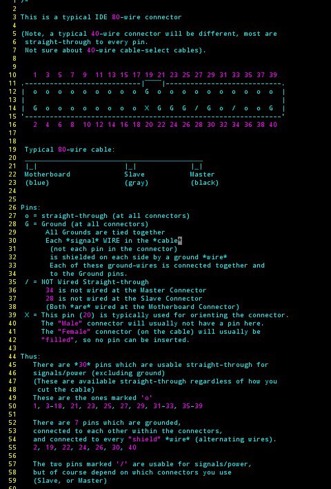
Briefly: 80-wire IDE cables are *great* for high-speed stuff... But the pinout is a bit more difficult than a straight-through 40-wire IDE cable, because the 80-wire cables have shielding (yay!) which is connected to specific pins designated as ground, as well as cable-select for master/slave.
This "document" shows which pins are available for your own use, and some suggestions as to how to make use of 'em.
---------------
80-wire IDE cables are quite useful, and are quite easy to acquire...
Cut off one end, and have a nice little jumper for between-boards on your own custom circuits. Strip the ends of the wires on that remaining cable and have a great "breakout" for a shit-ton of signals.
They have shielding between each signal wire. Cool. And that shielding is inherent to the cable itself, so there's no need to connect a whole bunch of pins to ground. Awesome.
BUT: That "automatic" shielding comes at a small price... You can't just use *any* of the pins in your cable for a signal. Below is a listing of the usable pins for your projects...
DEFINITELY SEE ALSO lower down the page, pinouts that are vertical... Why didn't I think of that? Thanks @Hacker404 . But, forgive me, I'm gonna be kinda partial to these for a little while, since I drew 'em.)
NOTE: The information below was determined by probing pins on a few cables. I have since run into cables wired differently (e.g. a master-only cable used insude a USB->IDE drive bay). Further, reading the specs at Wikipedia suggest a different standard-pinout than below! (e.g. pin34 at the mobo side is allegedly grounded, while the Master and Slave pin34s are connected together, ungrounded). Scroll to the bottom for the IDE pinout as compiled from several sources).
I think the main takeaway is just don't plan on using pins 20, 28, and 34. And maybe best to remove/clip those at the header, lest plausibly short something to ground, through the cable, unexpectedly.
Uses:
I have used this connector/cable combination for sending parallel video data between two boards over several inches. (e.g. between the "Master" and "Slave" connectors on the cable, the "Motherboard" connector and cable removed with scissors).
I also used a few inches of this cabling for the monitor I originally wrote this on, which used FPD-Link/LVDS. (Wire-pairs in LVDS are typically twisted together, but it seems to work fine in this setup with each signal-wire separated by a shield, as in the 80-wire IDE cable.) That display was 1600x1024 at 60Hz... way more than 33MHz pixel-clock.
I've, personally, settled on a couple "pinouts" that I've used in several places: one for parallel and one for FPD-Link video-data. It makes it quite easy to slap-together various converters... One board has DVI->Parallel, another Parallel->Dual-Pixel-FPD-Link. Another is used in the monitor I'm staring at: between the LVDS output on my VGA->LVDS converter (ebayed) and the unusual LVDS connector used by my monitor.
Also, I've recently found a pinout/orientation that works well with a Raspberry Pi's GPIO header for 18-bit color via DPI. [See below]
Of course, there's no reason to limit this connector to video signals (heck, it was used for hard-drives originally), but video's probably a pretty good stress-test of how clean these signals are... what data-rates we can expect to be reliable...


Expectables:
The latest-and-greatest of these cables are used with UDMA-133 (as I recall). That's 133MB/s, and I believe that's a guaranteed speed, which likely takes into account the lowest-quality cables they expect from manufacturers (and might even include older 80-wire cables from e.g. the UDMA-66 days?).
Thanks to @Yann Guidon / YGDES for correcting me on some logic... I think the best *guaranteed* signal on a UDMA-133 cable, then, is 33MHz.
That's down an entire 18inch cable, with two connectors, two loads, and surrounded by tons of really noisy power cables and other circuitry.
Also, I *think* they still use 5V-TTL-level signals, which is quite noisy in comparison to, say low-voltage TTL, or a differential-signal like LVDS...
All that to say, I think we can expect significantly higher reliable data-rates out of these cables than they're rated for... And if your project's below 33MHz, but you just want a reliable cable, these are highly recommended.
...for your hacking pleasure.
Thanks to @Hacker404 for redrawing these in a more browser-friendly manner!:
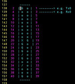
I'll leave the code-box for this one, for your copy/paste pleasure, remember it's *supposed* to be in fixed-width/monospace font... whether your webbrowser respects that is another thing entirely...
(Note, if you decide to copy-paste to, e.g., code documentation, it's MUCH easier, in this vertical orientation, to show which pins are being used for what... See examples below...)
     ------
 2  | G  o |  1 --------> e.g. Tx0
 4  | o  o |  3 --------< e.g. Rx0
 6  | o  o |  5
 8  | o  o |  7
10  | o  o |  9
12  | o  o |  11
14  | o  o |  13
16  | o  o |  15
18  | o  o |  17
20  | X  G  | 19
22  | G  o  | 21
24  | G  o |  23
26  | G  o |  25
28  | /  o |  27
30  | G  o |  29
32  | o  o |  31
34  | /  o |  33
36  | o  o |  35
38  | o  o |  37
40  | G  o |  39
     ------


Breakout Methods:
Update 11-1-16: This is a much better method for breakout than my under-breadboard-wiring (which is not shielded and defeats the purpose of the 80-wire shielded IDE cable)... #Breadboard adaptor for double-row pin headers
Update 11-7-16: Check out that link, above... it's way better than my other hack-job of more than a decade-ago:
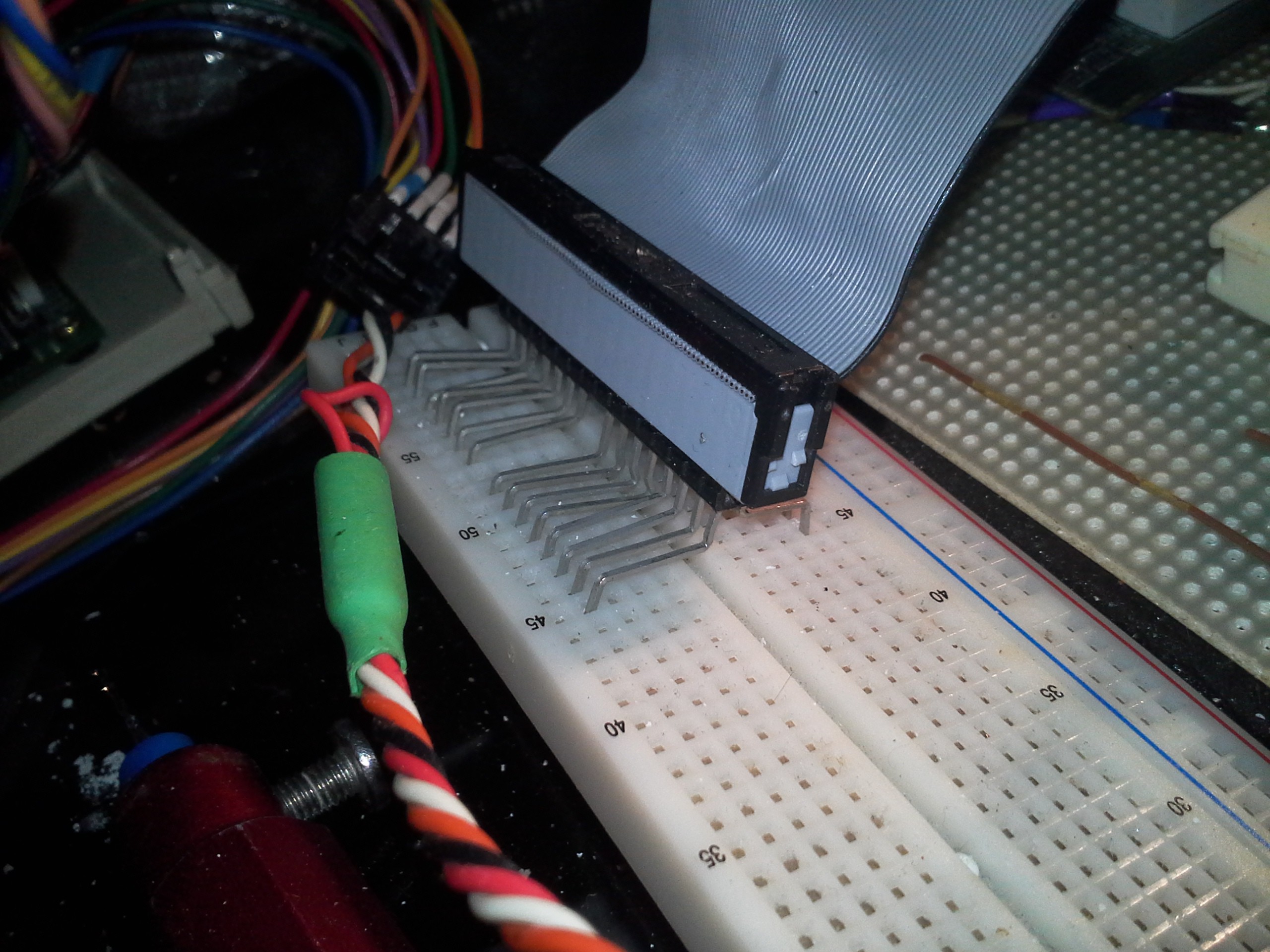
But note that these breakout-methods are probably more noise-immune than the bread-board-solder-up job shown later... That guy's got issues (the wires overlap the bus-bars, and they run right beside each other with no shielding).
Update 10-13-16: HMMM... http://www.mpja.com/28-Pin-GPIO-Breakout-Breadboard-Kit-for-Raspberry-Pi/productinfo/33050+MP/
 Not too different from:
 over at #sdramThingZero - 133MS/s 32-bit Logic Analyzer
Beware that NEITHER of the above take advantage of the inherent shielding of an 80-wire/40-pin IDE cable... (described below)....
Update 8-9-16: Cropping Motherboards
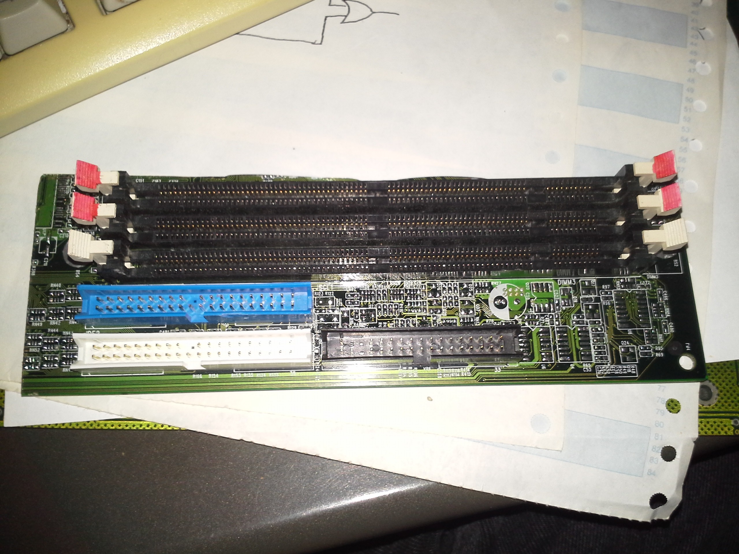
So, say you want to use your old fried motherboard for something completely different... in this case I'm working on an early prototype for #sdramThingZero - 133MS/s 32-bit Logic Analyzer... It was more laziness than anything that I kept the IDE (and floppy) connectors on this "motherboard cropping," but actually it'll be awesome! I can connect the (necessary) SDRAM pins to the IDE headers, and use this as a breakout-board! (And my cables are even shielded!) Awesome!
First-things-first: Be sure to remove all the other components... resistors, IC's, transistors... Yeah, probably even a good idea to get rid of the capacitors (unless you know they're only used for power). Careful with your heatgun, best from the back, works well with wide-areas. Gets a little tight *between* connectors, there were a slew of resistors inbetween. Heat up that soldering iron *hot* and put a huge blob of solder on it, big enough to touch both sides of the resistor... they should come up with a little work.. maybe put some aluminum-foil to protect the connectors and you might luck out and only get one burn-mark like I did. Anyways...
The next thing: Make sure those pins aren't shared, somehow. They're two separate channels, supposed to run simultaneously, so they *should* be completely independent, right? But yahknow, maybe power would be shared, or the Activity-LED (which is open-collector, as I recall)...
I only found One shared pin (besides the GNDs)... one which I wasn't expecting. Pin1 - Reset. K-Den... can't use that pin on *both* connectors for just *any* purpose...
(IDE pinouts are all over the webs. Note that there is no V+, only ground, and those are already handled in the "cable" pinout. Though, I suppose it's plausible one or two signals might be tied directly to V+ or GND... probably good to check.)
Otherwise, looks like I can use the above "cable" pinout for my needs.

-----
April 2020:
[August 2022, this is still running!]
Raspberry PI GPIO/DPI header:
Here we found a pinout that mostly-straight-through makes a Raspberry Pi's GPIO header mate with an 80-wire ATA cable... This is presently being used to run 18-bit (6 bits per RGB) Display Parallel Interface [DPI] to an LCD stripped from a broken portable DVD player
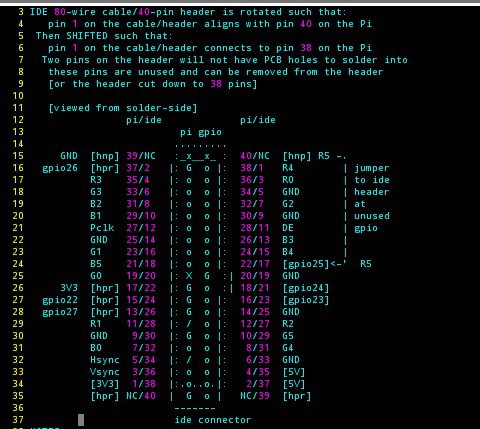
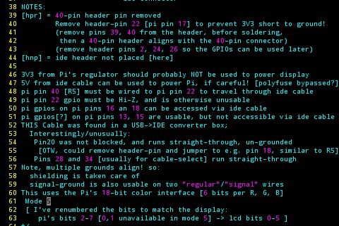

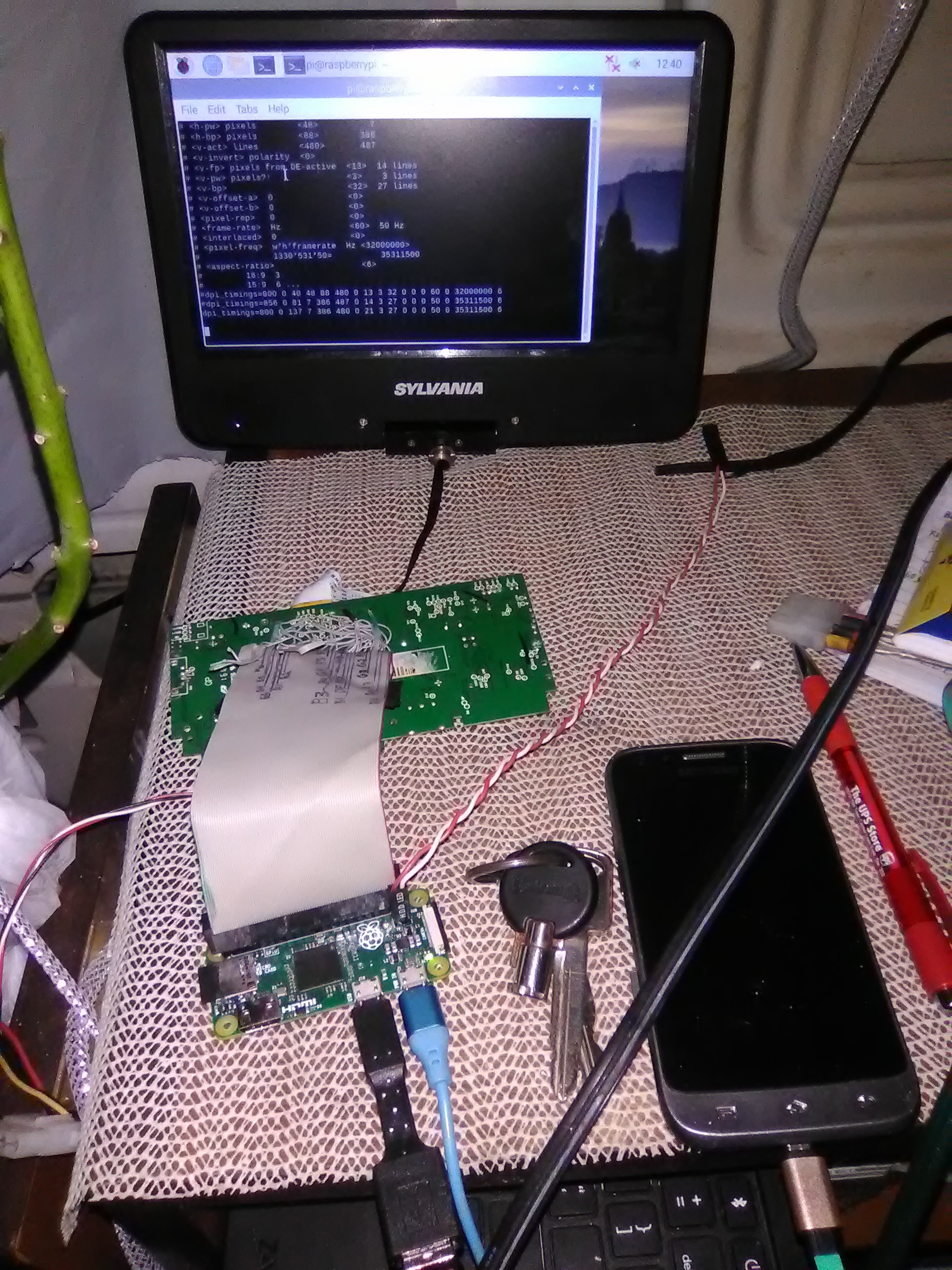
[Can't tell yah how much I lucked-out with this otherwise e-waste; labelled test-points! 0-ohm Resistors to the original processor! Just unsolder those to inject the Pi's signal. Friggin' thing was practically designed as a breakout board! Use the backlight and other power as-is... I think I can even figure out how to tap into the speaker amplifier.]
-----
August 2022: I dunno why I never actually put the IDE pinout, here. This is compiled from a few sources. Yeah, it's not complete... What are the directions/meanings of some of these things?
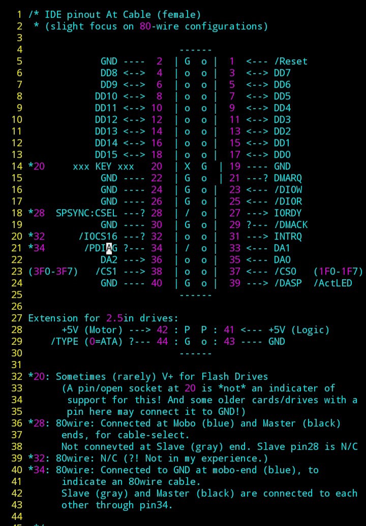
...I'm working toward my own sort-of "standardish" pinout for peripherals (and memory maybe) connected to an 8080-style bus... Since that's basically exactly what IDE is, with a few oddities (16bit instead of 8, a few dedicated signals, etc.), I might try to match that as much as possible. E.G. locations of D0-7, /RD, /WR, addresses, chip-selects...
When I come up with something, I'll post it here.
 Eric Hertz
Discussions
Become a Hackaday.io Member
Create an account to leave a comment. Already have an account? Log In.
Smart. I've been using the older 40 conductor IDE cables to connect our CNC BOB PCB to our stepper motors drivers for years, with one entire row (so every other wire) grounded... provides very nice shielding, no measurable cross talk between step signals at up to 100KHz over a foot or more of cable. I had accidentally purchased a bunch of these 80 wire cables some time ago, didn't think of this, and spent more time and effort than it was worth to ebay the damn things. Note to self: Never get rid of anything. Ever. Just let it slowly accumulate... ,o)
Are you sure? yes | no
Hah, yeah, that's a great way to make use of 40-wire connectors! The 80-wires are for us lazy-folk ;)
Are you sure? yes | no
Well, the 80 wire cables get you 30 signals, right? You only get 20 from the 40 wire cable (assuming you ground every other wire).
Are you sure? yes | no
True about the extra signal pins... An 80-wire cable is *almost* drop-in-replaceable in cases like yours *if* you used the even pins for ground (or maybe cut off the orientation-tab, drill out the filled pin 20, and flip it backwards if you used the odd-pins?). All except pin 19 :/
Are you sure? yes | no
------
---- 2 | G ck| 1 -------
4 | Hs V+| 3 Sync
---- 6 | DE Vs| 5 -------
---- 8 | B6 B7| 7 -------
10 | B4 B5| 9 Blue MSBs
---- 12 | B2 B3| 11 -------
---- 14 | G6 G7| 13 -------
16 | G4 G5| 15 Green MSBs
---- 18 | G2 G3| 17 -------
--G- 20 | X G | 19 -------
22 | G R7 | 21
24 | G R6| 23
26 | G R5| 25 Red MSBs
V+ 28 | / R4| 27
30 | G R3| 29
---- 32 | V+ R2| 31 -------
--V+ 34 | / B1| 33 -------
36 | G1 B0| 35 RGB
38 | R1 G0| 37 LSBs
---- 40 | G R0| 39 -------
------
Are you sure? yes | no
A little more HAD code box proof -
------
2 | G o | 1
4 | o o | 3
6 | o o | 5
8 | o o | 7
10 | o o | 9
12 | o o | 11
14 | o o | 13
16 | o o | 15
18 | o o | 17
20 | X G | 19
22 | G o | 21
24 | G o | 23
26 | G o | 25
28 | / o | 27
30 | G o | 29
32 | o o | 31
34 | / o | 33
36 | o o | 35
38 | o o | 37
40 | G o | 39
------
Are you sure? yes | no
Erm, I think I see where you're going with this... I shoulda done it vertical. Wonder why I didn't think of that.
Thanks for taking the time to do-so! I'll copy/paste into an actual code-box, if you don't mind.
Are you sure? yes | no
it's getting better, yes :-)
Are you sure? yes | no
UDMA-133 is 33MHz, dual data rate (falling and rising edge) and two bytes at once, IIRC :-)
Are you sure? yes | no
Indeed, thanks for the clarification, I'll fix it so I seem less ridiculous ;)
Are you sure? yes | no