 Eric Hertz
 Benchoff
 Tindie
 Sophi Kravitz
 johnowhitaker
 Hackaday
 Arya
Arya-
Floppy shenanigans
11/13/2017 at 20:07 • 6 commentsbeen learning a lot about floppy drives/disks/controllers lately, what with #Floppy "Fun" -- Backing up a unique Kay-Pro disk and #Improbable AVR -> 8088 substitution for PC/XT
Also finally started attacking a long-planned project to record audio directly onto floppy disks...
So, here I plan to throw random unexpected discoveries that may be useful for floppy endeavors of all sorts.
(Many Many more are buried in logs at the projects linked above).
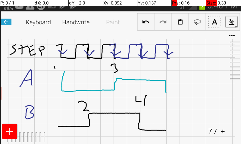
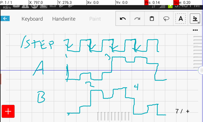
1) the /STEP input is *not* directly fed to the stepper motor driver. Boolean logic determines whether the drive pays attention to the /STEP input. Primarily: the drive *will not step* if /WG is active.
(This Teac drive manual actually shows the logic equation... and similar equations exist and are explained for other I/Os as well...)
2) if /WG is active when the index pulse arrives, the pulse is extended (dramatically) presumably to indicate to the host controller that the write process was truncated (?).
I vaguely recall reading about this extended pulse somewhere (and plausibly whether the write actually gets truncated, or whether it's allowed to overwrite the beginning of the track) but have yet to relocate that source.
3) microstepping?! Fiddling with /WG and /STEP timings, I noticed it may actually be plausible to acheive some level of microstepping. More logically, /STEP and /DIR could plausibly acheive this as well. Precision more likely than accuracy, so maybe not so useful when using disks for storage, but maybe something to fiddle with. (One thought... maybe possible to use Step/Dir microstepping in attempt to read tracks written on a poorly calibrated drive... or, e.g. where a 5.25in disk has an oblong hole, from years of wear).
The odd thing about /WG's effect on stepping... I was under the impression that /STEP must be (falling)edge-triggered... the outputs of the motor driver holding their new state after the edge. But then /WG's only effect should be that of either allowing or blocking the transition to the next state. Then there should be no fractional (or incomplete) steps. But almost certainly I could hear attempted steps cut short.
That would imply...
4) /STEP is not edge-triggered (?!)
And, actually, that makes some amount of sense based on my readings which I didn't quite wrap my head around until just now... combined with knowledge of the stepper motor driver chips used in some (macintosh) drives I've scrounged for their... wait for it... stepper-driver chips. These chips have two supply voltages for the motors... 12V for seeking and 5V for holding.
![]()
![]()
And the readings...? As I recall, the stepping-procedure for drives allots various (adjustable) time parameters for head movement... step-rates made sense to me; don't try to step too fast or the head won't overcome static friction, and steps will be missed. Head settling time; after a step, the motor will bounce briefly before settling into its new position... give it a certain amount of time to settle. But there were other step-timing parameters I didn't grasp... and I'm betting one of them is the duration of the /STEP pulse, which probably also determines the duration that the new state is supplied with 12V to nudge that motor into that new position... (note the drive I'm working with now only has a 5V supply, but may use a similar seek/hold scheme).
Aside: I used those motor drivers (once removed from the drives) for quite a bit of experimenting... #CD/DVD mechanisms and cartesian thinggie[s?] microstepping was definitely doable, but also causes quite a bit of heat... also, I worked with the driver chips themselves, which had separate...
Read more » -
Ode to My Oscilloscope...
11/07/2017 at 14:20 • 3 commentsI love my oscilloscope almost as much as one can love a machine...
My oscilloscope is *both* analog *and* digital.
This ain't no small potatoes...
We're talking: Its "bandwidth" is 20MHz, but I've diagnosed signals up to 128MHz, by adjusting various scaling-factors, in analog-mode.
In digital mode... well, it's pretty limited. 20MS/s means Nyquist would say we can't view anything greater than 10MHz, and then, only *barely*. Allegedly it can view repetitive signals at much higher sample-rates in "EQUIV" mode, which I assume does-so by *beginning* sampling at different delays after the trigger... I've had... sporadic luck with this.
But... at signal-rates lower than 10MHz, the digital-mode it does quite nicely... E.G. being able to "scroll" low-frequency signals is *awesome*... and, as far as I'm aware, completely impossible via analog-only means. Similarly, the ability to "hold" and then, essentially, "dump" a screenshot... well that's quite handy. It also does averaging and various interpolation-methods, but not things like... what I'mma call "windowing" wherein it'd show both the min and max values sampled at each sample-point (limited sample-memory, only seems to handle about one screen).
Now, in this era a 20MS/s 'scope ain't hard to come by... (nevermind RAM)... And, if I understand correctly, most digital 'scopes today that claim e.g. 20MHz sample at 10x that (200MS/s). So, by-far way better than this guy... (Though, there is a bit of debate as to whether cheapo-'scopes that claim such rates actually have the analog-front-ends to support it).
Anyways, I *have* actually diagnosed 128Mb/s signals, of certain forms, on my allegedly 20MHz analog 'scope... aliasing isn't a factor in the analog realm... It Can Be Done... And, so, analog is quite a nice thing at times...
(E.G. say your "20MHz" digital-only 'scope samples at 200MS/s... Nyquist says that you'll never see anything greater than 100MHz on that screen, without its being severely distorted by aliasing... Though, again, there may be ways 'round this, e.g. when you know a signal is repetitive, and your triggering is highly-accurate, and your software-programmer and circuit designer were "extremely" on the side of "clever").
.....
Anyways... It's been a long-running idea to replace the digital circuitry in my 'scope with something a little more capable in today's technology...
I've yet to come across a service-manual (as opposed to user-manual) for this guy, so I guess we'll have to start with some reverse-engineering...
.........
Oh, BTW, this is a Goldstar OS-3020, which appears to also have been labelled as LG (Lucky Goldstar?) OS-3020, also plausibly EZ-Digital OS-3020, It's of the OS-3000 series (which comes in 20, 40, and 60MHz varieties, along with the OS-3040, OS-3060... And I've seen e.g. OS-3020D, OS-3040D, and OS-3060D part-numbers, as well...
The user-manual shows BASIC listings for how to work with it... I mean, Cool. No?
......
Anyways, lacking schematics, here's some stuff for posterity:
The digital-board is located under the CRT... I guess the CRT's sheilding makes that possible.
The "big" components on the digital-board are:
U2412 HD64180RCP 10X (CPU, 10MHz, ZILOG Z180/Z80180 "fully-compatible", 1MB address-space... kinda funny I've been doing so much with Z80's recently. @Ziggurat29, any interest in disassembling this thing?).
U2402 XILINX XC2018-70 (Gate-Array... ??? Video-controller ???)
U2422 EPROM: TMS27C512-15 (Boot-ROM, 64KB)
.....
Also:
82C55 - (2x) Programmable Peripheral Interface
82C54 - (2x) Programmable Interval Timer
HM63021 - (2x) 2KByte "serial-access" SRAM
[H]A19211B - (2x) 20MS/s 8-bit A-D converters
... Read more » -
Contemplations on CMOS/TTL interfacing/hacks
01/05/2017 at 09:56 • 0 commentsDiscussion with @Ted Yapo and @jaromir.sukuba over at one of my project's logs wound 'round to the concept of level-shifting for various CMOS voltage-supplies and TTL... and it got me thinking.
The basic gist of that conversation was:
3.3V CMOS outputs can typically drive TTL inputs, but cannot be relied on to drive 5V CMOS inputs. Similarly, it's not reliable to feed a 5V TTL output into a 5V CMOS input.
Thus, there's the 74xCT series (ACT, HCT, etc.).
Basically, if you want to interface a TTL output signal to a 5V CMOS input, you should use the HCT or ACT series, rather than the HC or AC series, at that juncture in the circuit.
And, as I understand, that same series can be used to interface a 3.3V CMOS output to a 5V CMOS input.
There should be plenty of info about this 'round the web, and surely more reliably-documented than anything I could come up with. Look for "level-shifting" and check out the datasheets for these series.
------------
This "page" is mostly about hacks. These concepts should *NOT* be used in products, without *carefully* looking into the details that I won't be going into, here, to any extent except to throw out some ideas/experiences... for HACKS-SAKE.
-----
So, here are some of my experiences with the TTL series' running at 3.6V. We're talking e.g. the 7400, 74S00, 74LS00, and 74F00. They're only spec'd down to 4.5V, but I have had some luck using TTL at 3.6V, and you might too.
- For #sdramThing4.5 "Logic Analyzer", as regular-ol' glue-logic, a MUX, a latch, and some boolean-logic. There were definite performance-hits, but it was functional. I eventually "upgraded" to the HC series and, of course, the system was able to run faster. But. "It worked" with lowered-expectations, and a lot of experimentation, 'scoping, etc. with TTL's running at 3.6V.
- For that system, as well as my AVR-based LVDS-LCD controller: https://sites.google.com/site/geekattempts/home-1/drive-an-old-laptop-display-from-an-avr I've used 74LS86's (alternatively 74LS00's, and 74LS32's) running at 3.6V to drive the LVDS signals into old laptop displays. (much slower than normal FPD-Link... 16-128Mbps). Note that LVDS has a differential voltage of something like 0.1-0.3V, and has a 100ohm load at the end, which just happened to work out darn-near perfectly when directly-driven by the LS86's. Again, a lot of experimentation went into this! But the key, here, is that "it worked" *way* out of specs, and surprisingly reliably (two systems running 24/7 for over a year!).
Again, Neither of these experiences should be *expected* to work for you just because I happened to luck-out. But, for hack's sake don't be deterred from giving it a try (and expect it to be flakey!).
---------
Why? Mostly because those were the supplies I had on-hand.
Actually, the LS->LVDS system went through *many* iterations involving better-suited systems before settling on the (simplest) direct-driving via 74LS86. Another attempt used AHC parts, an inverter and a buffer. These are CMOS, rated for 3.3V, quite a bit faster, and most importantly (for LVDS) have much higher drive-strength, thus requiring series-resistors to keep the voltage low-enough.
--------
The recent discussion with Jaromir, as I said, got me thinking a bit about the xC vs xCT series. As I understand, the xCT series is basically identical to the xC series *except* that its inputs are rated for TTL-signals.
So... does that mean that the internal circuitry is identical, exclusive of the inputs?
The thing is: I've access to a bunch of ACT parts, but not so many AC. Similarly for HCT and HC. Others might run into the same when working on a project at a hacker-space, hackathon, convention, etc.
So, why the question...? Because ACT and HCT are *only* specified for 4.5-5.5V, just like TTL. But, if internally they're identical to the AC and HC series, then maybe they *can* run at the AC/HC power-supply-voltage-levels somewhat happily... (Maybe even with very similar timing-specs to the AC/HC...
Read more »
This user joined on 12/11/2014.


My Projects
Projects I Contribute To
My Pages
Things I've Built
Panhandlers Dream/Nightmare - CoCA/dorkbot
Get its attention, and it reaches out begging for change, then drops it in the donation-box, and the monkey plays a tune. First motion-control project, three axes, DC-motors with encoders.
IF VI WAS IX - guitar sculpture - Experience Music Project (EMP)
Many of these guitars play themselves via MIDI. I did a *LOT* of crimping and soldering on this project. A LOT. My entry into MIDI, microcontrollers, and motion-control systems; learning from the masters who put this together.
Liquid Letters - Snoqualmie Library
Had a huge role in the software/electronics, font-design, some assembly, and much more of this guy... One of the ol water-droplet displays, that spells words and some images. http://www.valleyrecord.com/community/25474554.html
Der Ring ^3 - Phaeno, Wolfsburg, Germany
Had a pretty significant role in the motion-control software/electronics of this guy (as well as a minor role in the mechanics) Picture from: http://www.futuremusic.com/news/june2006/trimpin.html
Piano-Bar art-car for TTITD
A car that is a gigantic piano! I played a minor role in wiring, some soldering, and some other assorted electronics and a teeny tiny bit of mechanical stuff (turning screws, mostly) for this guy, which went to Burning Man a few years back.
Trashbot
One spring they replaced all the trashcans on campus... so for April Fools, we chased people with one and shot them with a squirtgun. I guess it's one of R2D2's distant cousins.
TI-82 Backlight
Sometimes you just have to see a graph while laying in bed... Long ago I added an EL-backlight to my TI-82 graphing calculator. A few transistors for an oscillator, a transformer, and two unfortunately squat EL panels... Still handy today!
Audio Cassette player in your computer!
There's still some good music on my old audio-cassettes. Here I modified an old car-stereo's cassette-mechanism to fit in my desktop computer. https://sites.google.com/site/geekattempts/old-projects
Web-Controlled Robot
Before streaming-video was a thing, I attempted to make a web-controlled robot... https://sites.google.com/site/geekattempts/old-projects
TTL LCD Controller
This was my first huge TTL-based project, handled timing/memory for a 640x200 B/W display, which had to be reverse-engineered. https://sites.google.com/site/geekattempts/old-projects
SGI 1600SW VGA converter
The SGI 1600SW LCD is one of a kind, and not compatible with any common video-standard. Here I've hacked it to work with a standard VGA-to-LVDS converter. https://sites.google.com/site/geekattempts/home-1/sgi-1600sw
SDRAMthing - Use an SDRAM in "free-running" mode...
Feed back an SDRAM's Data lines to its Control lines and do quite a bit without MCU interaction. Drive an LCD display at full-resolution/color. Use it as a logic-analyzer, and more. https://sites.google.com/site/geekattempts/home-1/sdramthing
PowerBook G4 Wacom Digitizer and "BlueToothBee-Connector"
Yep, I actually installed a Wacom digitizer behind my PBG4's LCD... Had to hack the BlueToothBee to make it appear invisible to the TabletMagic driver. https://sites.google.com/site/geekattempts/home-1/wacom-tablet-bluetoother
Ridiculous PowerBook G4 Hacks
My PBG4 was my main development-system until recently... So I had to make it useful. Here's a whole bunch of hacks: Activity LED, Keyboard Replacement, Antenna hack, https://sites.google.com/site/geekattempts/home-1/ridiculous-pbg4-hacks
"Unlimited-axes" Motion-Control system (and Lego drawing machines!)
I needed some mechanics to test out my unlimited-axis motion-control system, so made some lego drawing-machines... https://sites.google.com/site/geekattempts/home-1/motion-control-and-legos
FPD-Link/LVDS LCD Single-Pixel to Dual-Pixel converter
Use a dual-pixel LCD in your single-pixel laptop... Upgrade that 12in PowerBook G4's pitiful 1024x768 to 1400x1050 https://sites.google.com/site/geekattempts/home-1/lvds-single-to-dual-converter/lvds-single-to-dual-converter-1
marioThing - Drive a Laptop Display with an AVR and two TTL chips
An AVR and two TTL chips can drive an old laptop-display! Here it's a Mario Power-Up (Question-Mark) box. Hit the bottom and receive a reward! https://sites.google.com/site/geekattempts/home-1/drive-an-old-laptop-display-from-an-avr
Projects I Like & Follow
 Paul McClay
 Rudraksha Vegad
 rand3289
 dearuserhron
 Kārlis
 Michael
 ziggurat29
 Starhawk
 Dr. Cockroach
Share this profile
ShareBits


Right on! Thanks for the +Like and the follow, dude... :)

Sorry for not answering your questions from "last year"
:o)
Wrote a reply only today: https://hackaday.io/project/26191-entries-for-the-flashing-light-prize-2017/log/64466-frequency-shifter-flashing-light-prize-2017/discussion-118601
Hey Eric, thanks for following and liking the One Square Inch TTL CPU, https://hackaday.io/project/161251-1-square-inch-ttl-cpu !
Hey there Eric and thanks for the follow & like for #Light Logic :-)

The entire boolean logic set handled by resistors and diodes! Who'd'a thunk?! Brilliant, my friend. Brilliant.

Thankyou for the follow, be sure to skull anything you like :)
https://hackaday.io/project/135292-ir-uv-invisible-qr-code-navigation-robotics

Thanks for the like on #Digibone mate!
Appreciated as always.
Sure-Thing! I see you've a few other prize entries, as well, this year! Good luck!


Right on! 3D printer-upgrades! Good luck with the prize!

Hi Eric Thanks for liking and following my project The Squid! Bluetooth motor control module..
Heck-yeah! Motor-control's awesome. But with Bluetooth? Even better. Good luck with the prize!
Hi Eric, thanks for liking the online 3D "Brain simulator" NeuronZoo https://hackaday.io/project/19287-neuronzoo !
Did you also try an example, or perhaps build a small "circuit" yourself ?
Sounds great! Been a bit busier than usual, but I'll give it a try real soon! Good luck with the prize!
Hi! Thanks for the following and liking my project #Fiber optic Power/Link tester !

Thanks for the like and follow on my #EXPLOG : Exploration Logger Really appreciate it :)
Hey there Eric, Thanks for the follow and like for the #Cardboard Relay - Uglytech is getting better :-)
Are you kidding? How could I not like a cardboard relay?!
Hi Eric, thanks for liking the one transistor flipflop, https://hackaday.io/project/112126-one-transistor-flipflop !

Thanks for the like my man, I've been following UR plight and wishing U strength :)
Thanks, my-man! I think it's working! I mean, if a friggin' tree can fall four feet from me and not even break the windshield, I gotta chalk it up to some sorta good-vibes coming from somewhere. Thanks, yo!
Good morning again Eric and welcome to my Cardboard Computer adventure as well :-)
hey ho Dr. C! been eyeing that bad-boy for some time. Nice work.
Hi Eric, thank you for liking the Risc Relay CPU ! (https://hackaday.io/project/11012-risc-relay-cpu)
Indeed! That's quite an undertaking... and will be a lot of clicking :)
Hey there Eric, Thanks for the follow and like of my Brainwarp project :-) IO is getting busy :-)
Heck yeah! That's a pretty awesome bunch of projects, there. And Brainwarp is a great name.
Hey there my man, thanks for the follow/like for #Starburst :-)