 luozhan2022
PCB components or supplies that need to be prepared in advance
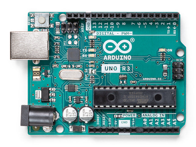
Arduino Uno Rev3
The Arduino Uno is a rigid PCB microcontroller board based on the ATmega328P (datasheet). It has 14 digital input/output pins (6 of which can be used as PWM outputs), 6 analog inputs, a 16 MHz ceramic resonator (CSTCE16M0V53-R0), a USB connection, a power jack, an ICSP header and a reset button. It includes everything needed to support the microcontroller; just connect it to a computer with a USB cable or power it with an AC-to-DC adapter or battery and you're ready to go. You can tinker with the Uno without worrying about doing something wrong, worst case you can replace the chips for a few bucks and start over.
"Uno," which means "Uno" in Italian, was used to mark the release of Arduino software (IDE) 1.0. The Uno board and Arduino software (IDE) version 1.0 is the reference version of the Arduino and has now evolved to newer versions. The Uno board is the first in a series of USB Arduino boards and is the reference model for the Arduino platform; see the Arduino Board Index for an exhaustive list of current, past, or obsolete boards.
SparkFun Bluetooth PCB Modem - BlueSMiRF Silver
BlueSMiRF Silver is the latest Bluetooth PCB wireless serial cable replacement! This version of the popular BlueSMiRF uses the RN-42 module, which has a somewhat smaller range than the RN-41 module used in BlueSMiRF Gold. These modems are used as serial (RX/TX) pipes. Any serial stream from 2400 to 115200bps is seamlessly passed from your computer to your target.
The remote unit can be powered from 3.3V to 6V for easy battery connection. All signal pins on the remote unit are 3V-6V tolerant. No level translation is required. Do not connect this device directly to a serial port. If you need to connect it to a computer, you will need an RS232 to TTL converter circuit.
MCL053MD
MCL053MD is a 5mm HE red circular LED PCB component with red diffuser lens, through hole mount, round lens, 15mcd luminous intensity, 625nm peak wavelength, 45° viewing angle. This LED light is made with GaAsP on GaP.
- 85mW power consumption
- -40 to +85°C operating temperature range
- Multicomp Pro products are rated 4.6 out of 5 stars
- 12 Month Limited Warranty *See terms and conditions for details
- 96% of customers would recommend to a friend

Male/Male Jumper Wires
Manufacturer: ADAFRUIT Manufacturer Part No: 758 Newark Part No.: 88W2570 Technical Datasheet: 758 Datasheet

RCC120610K0FKEA

The start of a Windows remote Arduino PCBA project
Program the Arduino
First, let's program the Arduino.
- Download and install the Arduino software from the official Arduino website.
- Connect your Arduino device to your computer using USB.
- Start the Arduino application.
- Verify you have the correct Arduino board selected under Tools > Boards
- Verify you have the correct COM port selected under Tools > Ports
- In the Arduino IDE, navigate to File > Examples > Firmata > StandardFirmata
- Confirm that StandardFirmata will use the correct baud rate for your connection. (see note on baud rates below)
- Press "Upload" to deploy the StandardFirmata sketch to the Arduino device.
Baud Rate
StandardFirmata communicates with Bluetooth devices using a serial line or via USB. By default it uses a baud rate of 57,600 bps. Depending on the configuration of your Bluetooth device, you may need to modify this rate. It can be found in the setup method and looks like this:
Firmata.begin(57600);
Change the value to the correct baud rate. For USB, this value is configurable in the device and Windows Remote Arduino connection parameters. If you are using a bluetooth PCBA, the baud rate depends on the device you are using.
Hardware Set Up
You can always start with a USB, WiFi or Ethernet connection, but let's cover the simple connection of a Bluetooth PCBA device and LED, we will use the Windows Remote Arduino library to turn the LED on and off via Bluetooth!
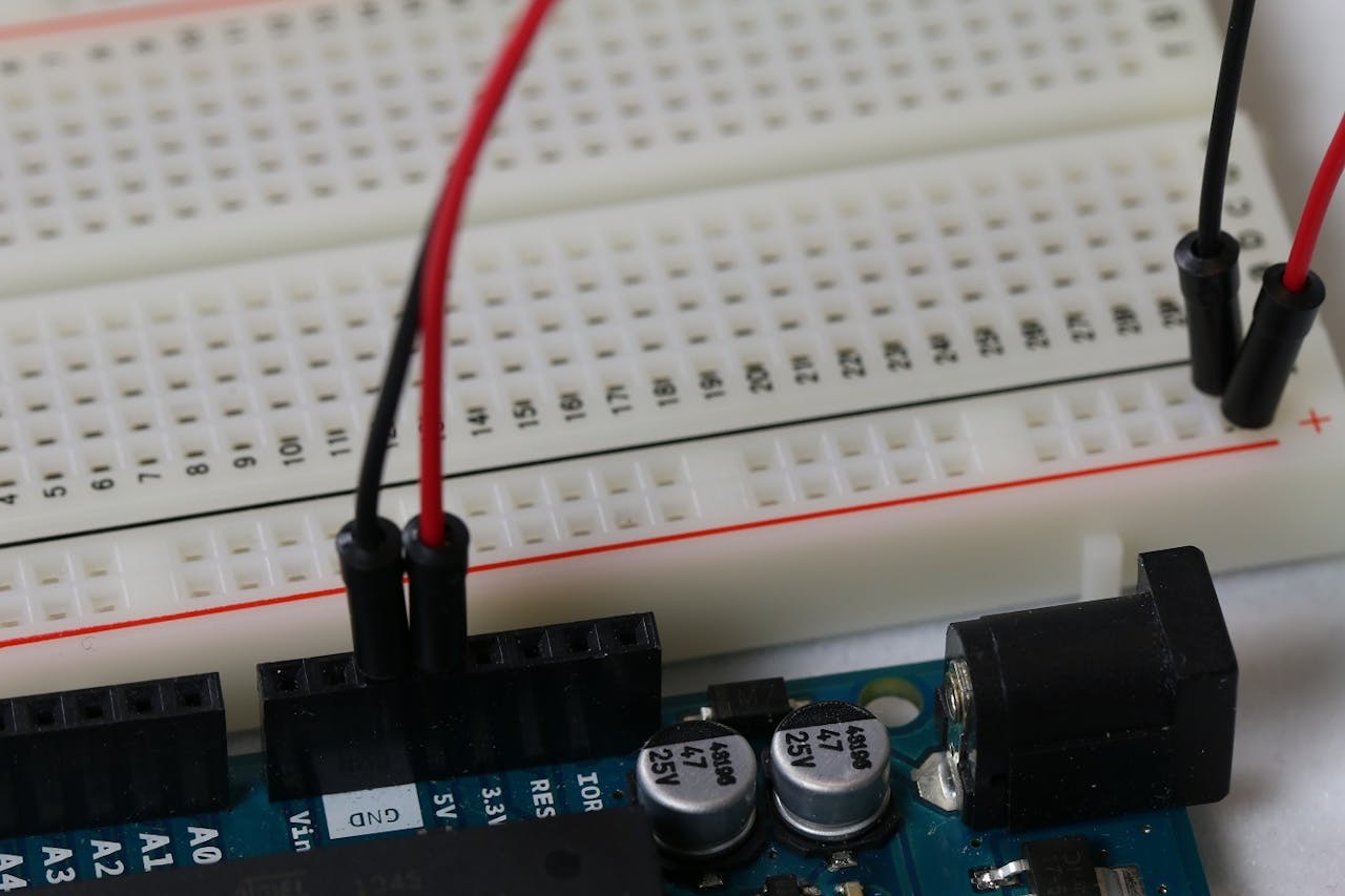
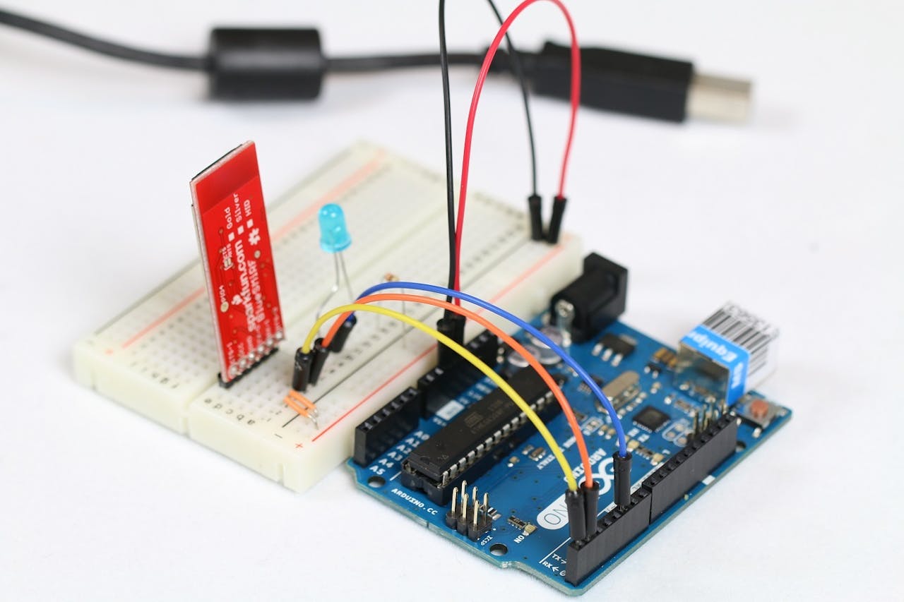
- Connect the power and ground rails on the rigid PCB to the 5V and GND pins on the Arduino respectively. Power connections are easily tracked using color-coded wires (red and black).
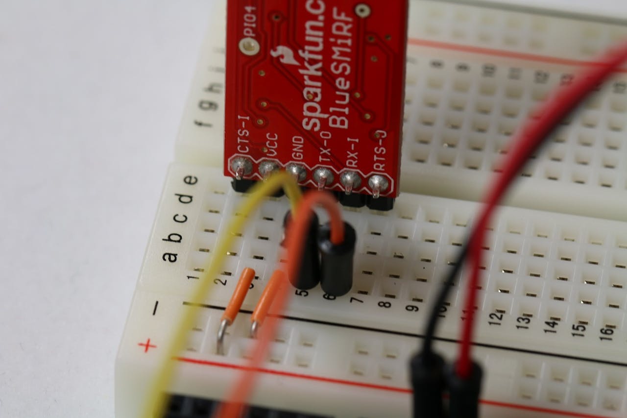
- Plug the Bluetooth device onto the rigid PCB and connect the VCC and GND pins to the power and ground rails on the rigid PCB respectively.
- Connect the TX-0 pin on the Bluetooth device to the RX pin on the Arduino. Likewise, connect the RX-1 pin on the Bluetooth device to the TX pin on the Arduino.
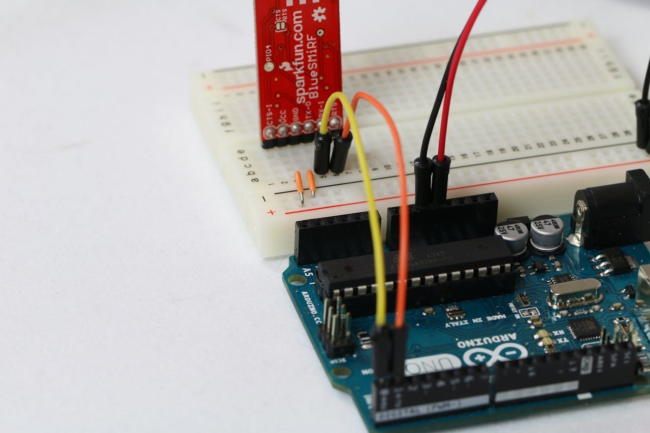
- Note that the yellow wire in the picture goes from the Bluetooth device's transmit pin to the Arduino's receive pin, and the orange wire does the opposite. This step is critical to establishing serial communication between the Bluetooth device and the Arduino, allowing messages transmitted from one device to be received by the other.
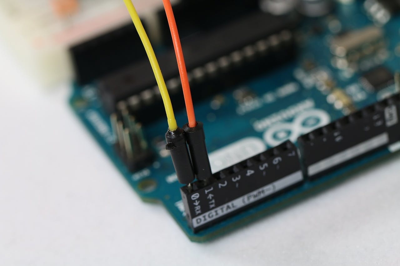
- Before making this connection, make sure your code is uploaded to the Arduino. The Arduino Uno uses the same serial (TX and RX) pins to flash the device, this prevents any code being uploaded to it while another device is connected to those serial pins.
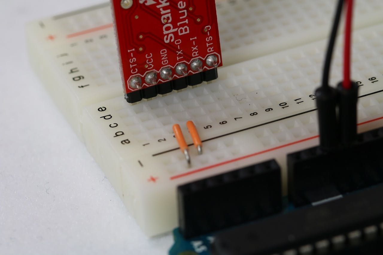
- Add an LED to the rigid PCBA. Note that the longer (or bent) leg is the anode (positive) and the shorter leg is the cathode (negative).
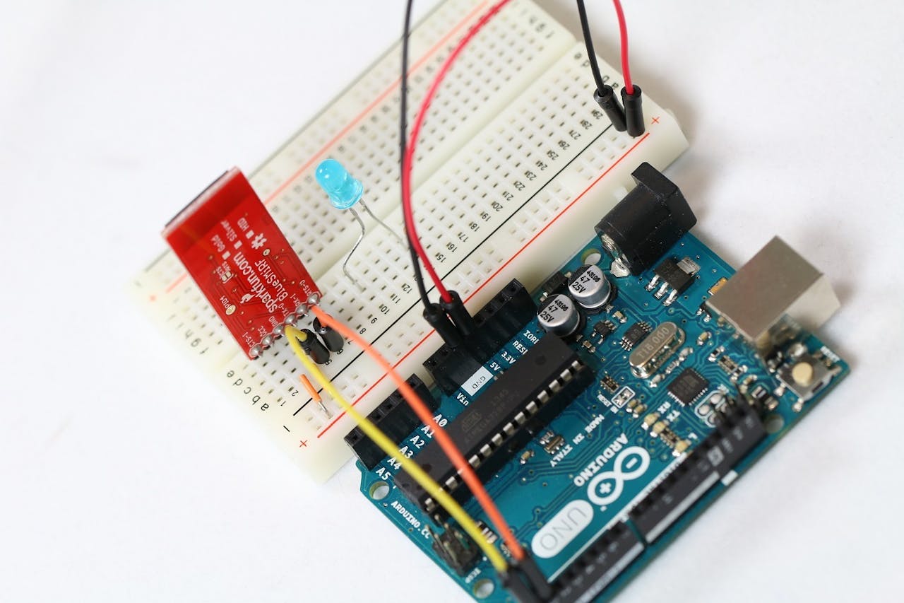
- Connect the cathode of the LED to the ground rail of the rigid PCB using a 330Ω resistor. A 330Ω resistor is striped orange, orange, brown, gold as shown.
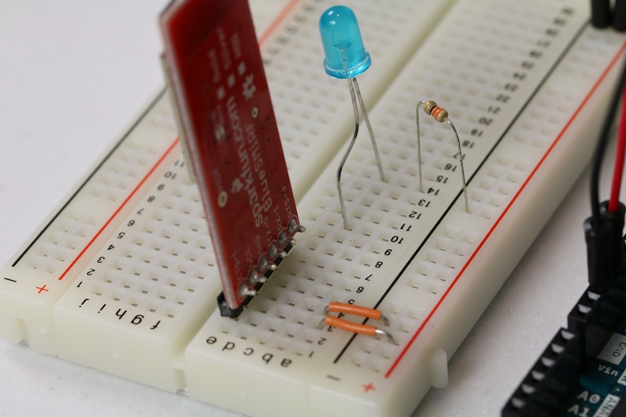
- Connect the anode of the LED to any digital I/O pin on the Arduino. We use pin 13 in our example.
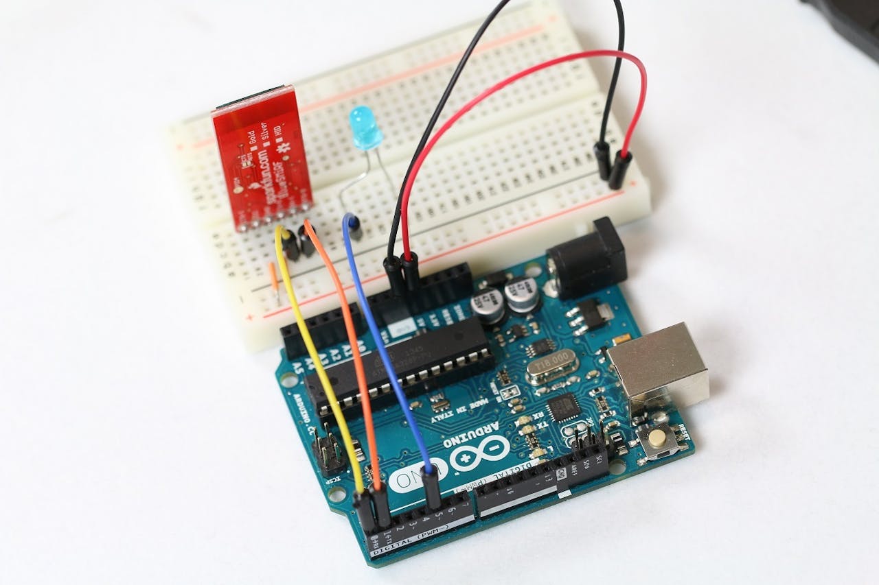
Your FS PCBA setup is now ready! It should look similar to the setup shown in the image below.
FS PCBA Project Code
Arduino sketching
Install Arduio Firmata Library:
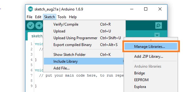
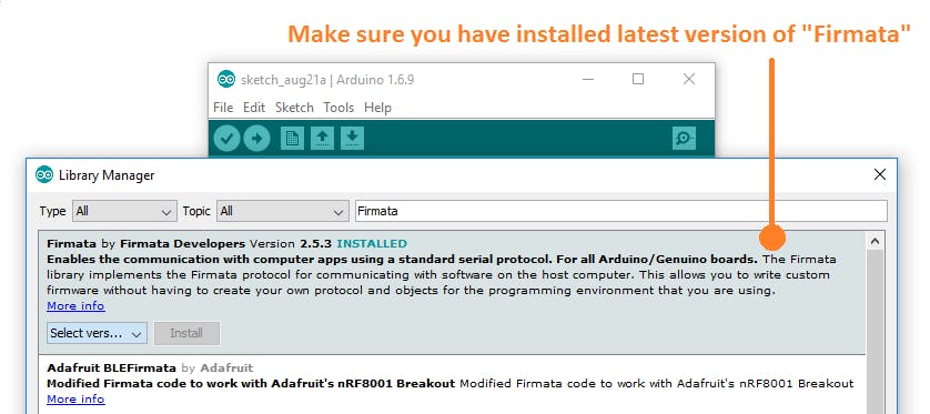
Go to Sketch Menu/Include Libraries/Manage Libraries and search for "Firmata" and install the latest version of the library.
Now open and upload the "StandardFirmata" example from File/Examples/Firmata/StandardFirmata.
It is done on the Arduino side. Now we will see the application for Windows Universal Platform.
Windows Universal Platform App
Download the example repository here. If you'd rather create your own electronics PCB fabrication project, follow the project setup guide here.
Now that we're all set, let's get into some code!
- Create your project
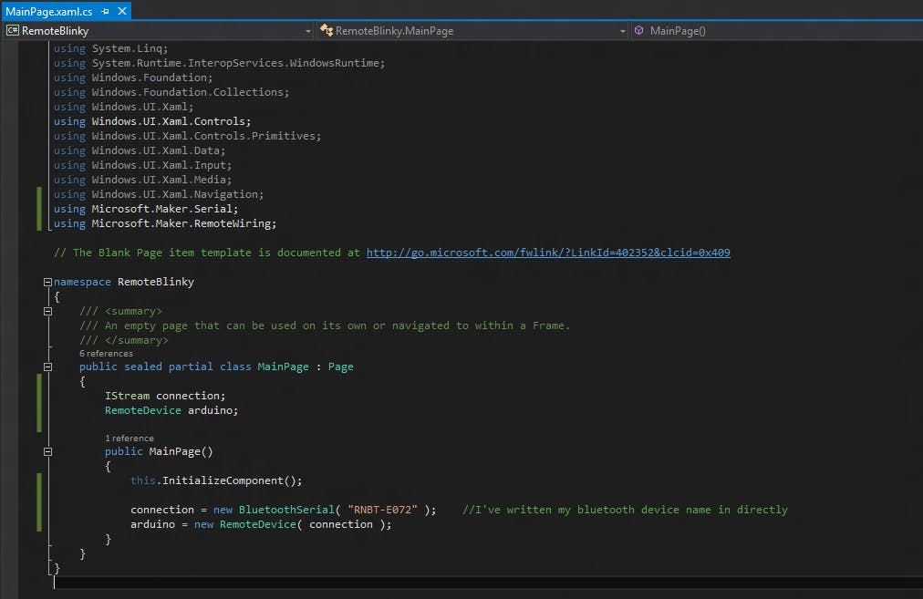
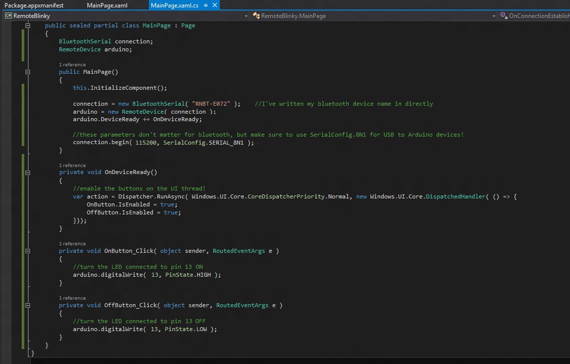
I set up a project called FS PCBA RemoteBlinky following the steps in the setup guide. In the screenshot below, you'll see the code-behind file, MainPage.xaml.cs, which simply creates a Bluetooth connection object and passes it to the RemoteDevice class in the constructor. You'll see that I specified my device name in this example. You can also enumerate available devices by calling the static .listAvailableDevicesAsync() function on the BluetoothSerial (and USBSerial) class before constructing the object.
Notes for USB flex PCBA:
USBSerial has many options for specifying your device. In the constructor, you can provide the device's VID and PID, just the VID, or a DeviceInformation object (obtained from the listAvailableDevicesAsync function above). Likewise, BluetoothSerial allows you to provide a device ID (as a string), a device name (also a string), or a DeviceInformation object.
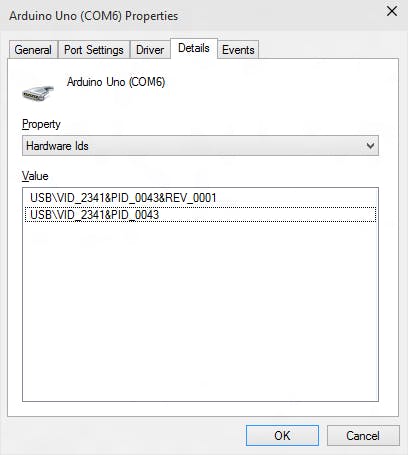
You can get the VID and PID combination of a USB device by following these steps:
Open Device Manager from Control Panel or by pressing the Windows + Pause keys together and selecting the Device Manager link on the left.
- Expand the Ports (COM and LPT) menu
- Right click on your Arduino device and select properties
- On the Details tab, select Hardware ID from the drop-down menu.
- You may see multiple entries in the Value box, but any entry will have a matching PID and VID.
- These entries have the format "USB\VID_****&PID_****", where **** is the numeric ID value.
USBSerial usb = new USBSerial( "VID_2341", "PID_0043" ); Guaranteed to work only with the following hardware devices:
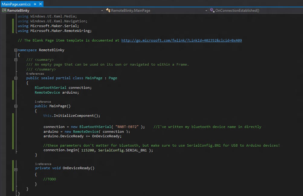
Next, I'll add a callback function to the RemoteDevice object's DeviceReady event. This function is automatically called when the Bluetooth Flex PCB device is connected and all necessary settings have been initialized. You'll notice that I haven't implemented anything in that function at this point. Finally, call .begin() on the connection object to tell it to connect.
Flex USB PCBA code considerations:
The parameters of the .begin() function don't matter for bluetooth flex PCBA, but you have to use the same baud rate on Arduino and UsbSerial object (first parameter). Also, the second parameter must be "SerialConfig.8N1". The rest of the example works exactly the same no matter which connection type you use.
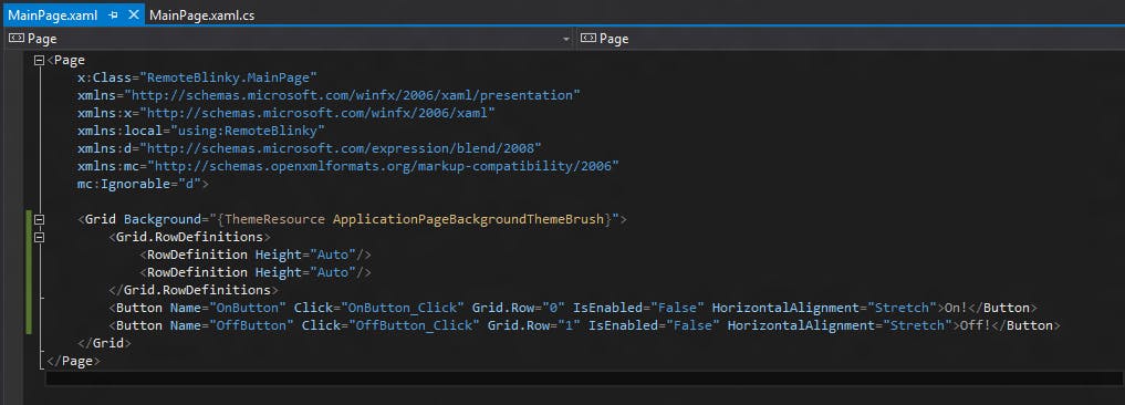
Jump to the MainPage.xaml file and create a few buttons that turn the LEDs on and off. You'll notice that I've added the button callback to the Click event and set the IsEnabled property to false, FS Tech will explain why below!
- I implemented three functions in this step. First, the OnDeviceReady function now enables the button on the UI thread! This ensures that the button is only enabled when the Bluetooth connection is ready, as this usually takes a few seconds to happen.
- I also set up .digitalWrite() calls in the button callbacks OnButton_Click and OffButton_Click
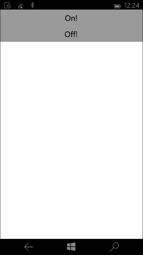
Flex PCBA Build and Deploy! Once connected, your button will be enabled and you can turn the LED on and off at will! Here's a screenshot of this basic example running on Windows Phone 10.
I really hope you enjoy duplicating this project and using it as a baseline for an incredible new set of PCBA projects! You can quickly go from PCB to PCBA with PCB assembly to get it done in no time.
Discussions
Become a Hackaday.io Member
Create an account to leave a comment. Already have an account? Log In.