-
Water Turbidity Indicator Design Principles
01/06/2023 at 02:14 • 0 comments![water turbidity indicator]()
We usually use turbidity to measure the quality of water, which is considered accurate and it can clearly reflect the quality of water. In fact, we consider particles in water larger than 2 microns to be turbid.
Next we will make a simple electronic project of water turbidity indicator. Before starting this project we need to prepare some cheap PCB components and understand the general concept of water turbidity indicator.
Description of Easy Water Turbidity Indicator
![Water Turbidity Indicator Design Schematic]()
The above picture is the schematic diagram of this simple circuit, through which we can design water quality inspection equipment for low viscosity, low corrosive liquids, such as streams, lakes, etc. As shown in the picture above, this project is based on ASAIR's AZDM01 photoelectric turbidity sensor.
AZDM01 is a photoelectric turbidity sensor, which can be operated by applying a voltage of 5V across it, and a larger voltage requires replacing the resistor. After being powered on, AZDM01 can emit an infrared beam with a wavelength of 940nm, which can easily pass through the liquid to be tested. When the sensor inside AZDM01 receives the light signal, it will convert the light intensity into an analog output signal to estimate the turbidity of the target liquid.
The figure below shows the data obtained from the official website of the AZDM01 turbidity sensor:
![pin symbol]()
The rest of the PCBA is a single-supply dual operational amplifier based on the LM358 IC (IC1A). Here the op amp is configured as a coarse inverting voltage comparator. It is worth noting that a comparator is a device that can have two inputs. Usually we use normal op amps that have their outputs not close to the supply rails, but somewhere in between, but that's not a significant number in this simple application.
In this water turbidity indicator, when the supply voltage is less than the threshold voltage, the output of the operational amplifier moves to the positive rail. Similarly, when the supply voltage is greater than the threshold voltage, it moves toward the negative rail. Resistor divider R3-R4 and supply voltage set the threshold voltage.
From the schematic diagram of the PCB, when the power supply voltage of the turbidity sensor is applied to the 2.2KΩ load resistance, the current will be greater than the rated value, and the green indicator light is on at this time, which means that the tested liquid is clear. On the contrary, when the red indicator light is on, it means that the tested liquid is cloudy. To limit the current flow, we will add a 100Ω resistor to the board to ensure proper operation of the circuit. It is worth mentioning that we have installed another resistor with a resistance value of 510Ω inside the simple version of the turbidity sensor for the same purpose as above. As shown below
![A resistor with a resistance value of 510 ohms]()
Assembly and functional testing
- First of all, we need to install the core circuit board components on the PCB, and conduct a simple test on it to ensure that the circuit can operate normally according to the design principle.
- Submerge the simple version of the turbidity sensor in clean water and observe whether the green LED lights up.
- Submerge the simple version of the turbidity sensor in turbid water and watch for the red LED to light up.
- PCB assembly needs to pay attention to whether the components correspond to the positions on the schematic diagram, otherwise failures may occur, and components need to be desoldered to rebuild.
Summarize
If the prototype works fine, the water turbidity indicator circuit can be moved to a perf board or custom printed circuit board. A suitable housing can also be used to protect the entire electronics.
As a side note, a static threshold is used here, but it can be changed to a dynamic threshold by replacing the voltage divider with a 100KΩ trimpot or potentiometer. Additionally, an unused operational amplifier (IC1B) can be connected as a unity-gain buffer/voltage follower, feeding the analog output of the turbidity...
Read more » -
Windows Remote Arduino
11/24/2022 at 02:48 • 0 commentsPCB components or supplies that need to be prepared in advance
Arduino Uno Rev3
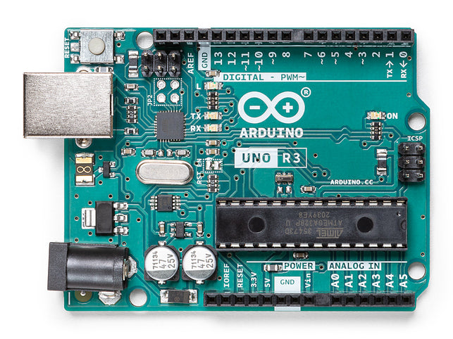
The Arduino Uno is a rigid PCB microcontroller board based on the ATmega328P (datasheet). It has 14 digital input/output pins (6 of which can be used as PWM outputs), 6 analog inputs, a 16 MHz ceramic resonator (CSTCE16M0V53-R0), a USB connection, a power jack, an ICSP header and a reset button. It includes everything needed to support the microcontroller; just connect it to a computer with a USB cable or power it with an AC-to-DC adapter or battery and you're ready to go. You can tinker with the Uno without worrying about doing something wrong, worst case you can replace the chips for a few bucks and start over.
"Uno," which means "Uno" in Italian, was used to mark the release of Arduino software (IDE) 1.0. The Uno board and Arduino software (IDE) version 1.0 is the reference version of the Arduino and has now evolved to newer versions. The Uno board is the first in a series of USB Arduino boards and is the reference model for the Arduino platform; see the Arduino Board Index for an exhaustive list of current, past, or obsolete boards.
![Arduino Uno Rev3]()
SparkFun Bluetooth PCB Modem - BlueSMiRF Silver
BlueSMiRF Silver is the latest Bluetooth PCB wireless serial cable replacement! This version of the popular BlueSMiRF uses the RN-42 module, which has a somewhat smaller range than the RN-41 module used in BlueSMiRF Gold. These modems are used as serial (RX/TX) pipes. Any serial stream from 2400 to 115200bps is seamlessly passed from your computer to your target.
The remote unit can be powered from 3.3V to 6V for easy battery connection. All signal pins on the remote unit are 3V-6V tolerant. No level translation is required. Do not connect this device directly to a serial port. If you need to connect it to a computer, you will need an RS232 to TTL converter circuit.
MCL053MD
MCL053MD is a 5mm HE red circular LED PCB component with red diffuser lens, through hole mount, round lens, 15mcd luminous intensity, 625nm peak wavelength, 45° viewing angle. This LED light is made with GaAsP on GaP.
- 85mW power consumption
- -40 to +85°C operating temperature range
- Multicomp Pro products are rated 4.6 out of 5 stars
- 12 Month Limited Warranty *See terms and conditions for details
- 96% of customers would recommend to a friend
![14N9416-40.jpg (320×193)]()
Male/Male Jumper Wires
Manufacturer: ADAFRUIT Manufacturer Part No: 758 Newark Part No.: 88W2570 Technical Datasheet: 758 Datasheet
![88W2570-40.jpg (200×200)]()
RCC120610K0FKEA
![MFG_RCC1206.jpg (640×640)]()
The start of a Windows remote Arduino PCBA project
Program the Arduino
First, let's program the Arduino.
- Download and install the Arduino software from the official Arduino website.
- Connect your Arduino device to your computer using USB.
- Start the Arduino application.
- Verify you have the correct Arduino board selected under Tools > Boards
- Verify you have the correct COM port selected under Tools > Ports
- In the Arduino IDE, navigate to File > Examples > Firmata > StandardFirmata
- Confirm that StandardFirmata will use the correct baud rate for your connection. (see note on baud rates below)
- Press "Upload" to deploy the StandardFirmata sketch to the Arduino device.
Baud Rate
StandardFirmata communicates with Bluetooth devices using a serial line or via USB. By default it uses a baud rate of 57,600 bps. Depending on the configuration of your Bluetooth device, you may need to modify this rate. It can be found in the setup method and looks like this:
Firmata.begin(57600);
Change the value to the correct baud rate. For USB, this value is configurable in the device and Windows Remote Arduino connection parameters. If you are using a bluetooth PCBA, the baud rate depends on the device you are using.
Hardware Set Up
You can always start with a USB, WiFi or Ethernet connection, but let's cover the simple connection of a Bluetooth PCBA device and LED, we will use the Windows Remote Arduino library to turn the LED on and off via Bluetooth!
- Connect the power and ground rails...
-
LED PCBA UV Torch
11/21/2022 at 03:05 • 0 commentsWhat is Needed to Start a PCBA UV Torch Project Here is a list of suggested key components needed for this small project:
- 395nm 5mm UV (ultraviolet) LED x 12
- 4V/500mAh SLA (sealed lead acid) battery x 1
- N/O (normally open) type momentary push button switch x1
UV light panel structure A UV LED PCBA panel - the head of a stain finder torch - can be fabricated on a small rectangular protoboard (so-called perfboard/veroboard). Below is the wiring diagram for the UV LED Panel.
![UV LED PCBA structure]()
Note that a common 5mm Chinese FS PCBA UV LED has a typical forward voltage (vf) of 3.4V and a typical forward current (If) of about 15mA. Check the actual specifications of the UV LEDs you will be using in your project and fine-tune your final solution accordingly. Since the UV LEDs are powered by 4V SLA batteries, a parallel combination is used here.
And, here's the UV LED panel part of my quick prototype:
![FS PCBA UV LED]()
After the light board is successfully built, test it with a 3V button lithium battery (such as CR2032) to make sure it is ok (see the picture below).
![LED PCBA board]()
Set up the black light engine Next you can complete the wiring as shown in the picture below. Ordinary lenses and reflectors don't work well with UV LEDs, so this common white LED torch optic is not recommended here. Also, the supporting optics are not really important in this project - just go with the bare light PCB panel.
![PCBA]()
For push button switches you should use a type capable of switching a minimum of 500mA at 5VDC. Of course you could simply put a solid rocker/slide switch between the battery output and UV input in place of the momentary push button switch - meaning a (ny) switch capable of taking the current and voltage of the control board.
If everything looks good so far, you can give the bare metal a test run to see what the black light looks like. Recall that ultraviolet wavelengths are used to excite materials that fluoresce under inspection. The material being examined fluoresces by absorbing ultraviolet wavelengths and emitting light somewhere in the visible spectrum. It has been observed that many manufacturers of stain finder torches choose 395-400nm UV LEDs rather than the more expensive 365nm UV LEDs. I've found that in most cases, 395nm is as effective (maybe a bit better) than 365nm UV LEDs in terms of fluorescence.
If you want to make a fancy UV stain detector flashlight, some mechanical work is required, but luckily not much. The whole build can of course be built into a rectangular enclosure, for the enclosure you can use a 3D printed PCBA's enclosure, although a handmade box is another option (my sun is not up yet)!
For the first test, I placed a pair of green COB LED sticks (unpowered of course) on a black cutting mat and illuminated it with UV light from a distance of about 20cm. Below you can see the "fluorescent" results of an experiment run under my basic 395nm black light engine. Great, isn't it?
![]() Unorthodox battery charger PCBA
Now you need to think about power to keep the SLA battery fully charged. Building your own charger circuit for a 4V SLA battery is not as difficult as you might think. Here, it would be even better if you could build a (almost) universal USB-compatible charger circuit capable of receiving USB standard 5VDC power from any USB source and charging the battery. There are various ways to build this simple battery charger circuit without using a dedicated charge controller chip. Time to try it out with a tried-and-true idea. See the diagram below.
Unorthodox battery charger PCBA
Now you need to think about power to keep the SLA battery fully charged. Building your own charger circuit for a 4V SLA battery is not as difficult as you might think. Here, it would be even better if you could build a (almost) universal USB-compatible charger circuit capable of receiving USB standard 5VDC power from any USB source and charging the battery. There are various ways to build this simple battery charger circuit without using a dedicated charge controller chip. Time to try it out with a tried-and-true idea. See the diagram below.![]()
From a technical point of view, there really isn't any complex design math needed to fit it, but calling the basic SLA battery chemistry, the maximum charge current for a small (dual cell) 4V/500mAh SLA battery shouldn't be much higher than about 100mA. In addition, the highest charging voltage should be limited to 2.42V/cell, and then lowered to 2.20V/cell for float charging. I was just looking for a simple solution and it worked!
![]()
Some Mysterious Battery PCBA Chemistry ...
Read more »


 Unorthodox battery charger PCBA
Now you need to think about power to keep the SLA battery fully charged. Building your own charger circuit for a 4V SLA battery is not as difficult as you might think. Here, it would be even better if you could build a (almost) universal USB-compatible charger circuit capable of receiving USB standard 5VDC power from any USB source and charging the battery. There are various ways to build this simple battery charger circuit without using a dedicated charge controller chip. Time to try it out with a tried-and-true idea. See the diagram below.
Unorthodox battery charger PCBA
Now you need to think about power to keep the SLA battery fully charged. Building your own charger circuit for a 4V SLA battery is not as difficult as you might think. Here, it would be even better if you could build a (almost) universal USB-compatible charger circuit capable of receiving USB standard 5VDC power from any USB source and charging the battery. There are various ways to build this simple battery charger circuit without using a dedicated charge controller chip. Time to try it out with a tried-and-true idea. See the diagram below.

 Lutetium
 Dan
Dan Michiel Spithoven
 pj
pj Vinch
Vinch Brijesh Sondarva
 Bryan Howard
 Ansaf Ahmad
 Curt White
 Brian
Brian SirClover
 David Prutchi
 TM
TM Pnoxi
Pnoxi Stefan Wagner