 Discreet Mayor
Did some tests with APA102C RGB LEDs. These theoretically work above 4.5V, but I was successful providing 3.3V for both signal and VCC, so no level shifting necessary ...at least with the batch I have! Another thing that doesn't appear to be necessary is the end frame specified in the datasheet.
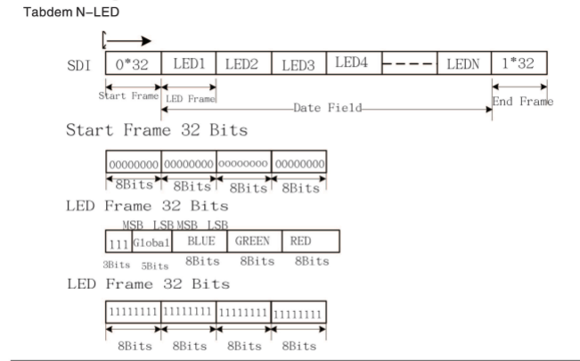
If you look at the end frame, it would look like a fully lit extra LED after N LEDs. I've actually found that this is exactly what happens (eg, if you output data for 32 LEDs and add the end frame, you get a 33rd white LED, probably not what you want). I've removed the end frame from my driver, and everything else behaves as expected.
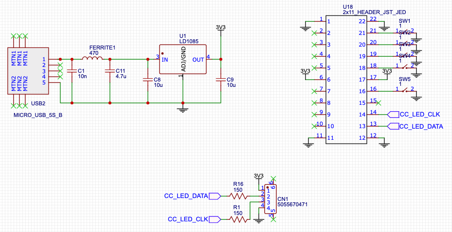
Ultra-simple circuit for use with these guys, with provisions for use without a wireless MCU with tactile switches for mode changes:
Discussions
Become a Hackaday.io Member
Create an account to leave a comment. Already have an account? Log In.