 Sam
SamPotentiometers, also known as pots, are widely used in electronics for their variable resistance properties. Understanding the proper wiring of potentiometers is essential for incorporating them effectively into circuits. This comprehensive guide aims to provide an overview of potentiometer wiring, explaining the different types of potentiometers and their connections. By following this guide, electronics enthusiasts and engineers will gain the knowledge necessary to utilize potentiometers correctly and optimize their circuit designs.
Types of Potentiometers
Potentiometers come in various types, each with its own characteristics and applications. The most common types include rotary potentiometers, slide potentiometers, and trimmer potentiometers.
Rotary potentiometers are cylindrical devices with a rotating shaft. They are often used for adjusting volume, controlling brightness, or setting parameters in electronic circuits. Slide potentiometers have a linear sliding mechanism and are commonly found in audio mixing consoles or as faders in audio equipment. Trimmer potentiometers, also known as preset potentiometers, are small adjustable resistors used for fine-tuning circuits during assembly or calibration.
Potentiometer Wiring Basics
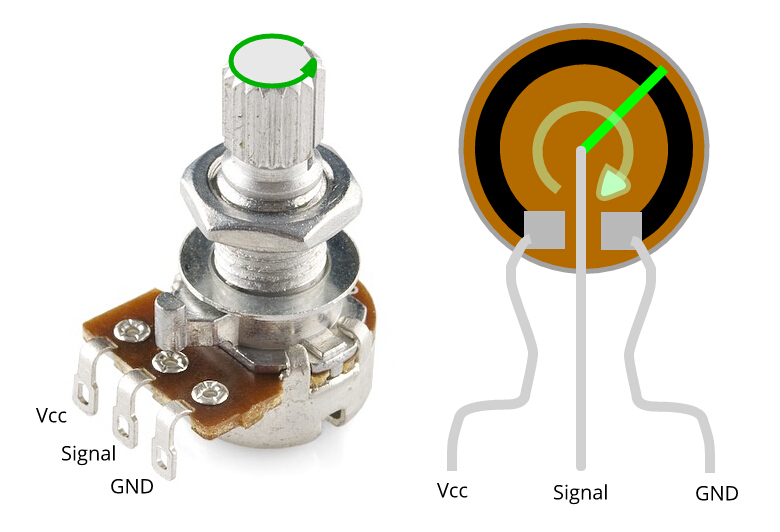
The wiring of a potentiometer typically involves three terminals: the outer terminals and the center terminal. The outer terminals are connected to the fixed ends of the resistive element, while the center terminal, also known as the wiper terminal, is connected to the movable contact.
For rotary potentiometers, one outer terminal is connected to the power supply or ground, and the other outer terminal is connected to the load or circuit input. The center terminal is connected to the circuit's output, allowing the user to adjust the resistance and control the signal or parameter.
Slide potentiometers follow a similar wiring scheme. One outer terminal is connected to the input or output of the circuit, while the other outer terminal is connected to the opposite end. The center terminal, connected to the wiper, provides the variable resistance when the slider is moved.
Trimmer potentiometers typically have two outer terminals and do not have a center terminal. The adjustable resistance is achieved by turning a screw or rotating a small knob, altering the resistance value between the outer terminals.
Wiring Configurations and Applications
Potentiometers can be wired in various configurations to suit different circuit requirements. Common configurations include potentiometers used as voltage dividers, variable resistors, or rheostats.
In voltage divider applications, the potentiometer is connected as a potential divider circuit, allowing a variable voltage output based on the position of the wiper. This configuration is often used for volume controls, brightness adjustments, or sensor calibration.
Potentiometers can also function as variable resistors, where one outer terminal and the center terminal are connected, and the other outer terminal is left unconnected. This configuration allows the potentiometer to provide a variable resistance within the circuit, regulating current flow or adjusting the gain in an amplifier.
Rheostats are another common wiring configuration, particularly with slide potentiometers. In this setup, one outer terminal and the center terminal are connected, while the other outer terminal is disconnected. Rheostats are frequently used in applications where variable resistance is needed to control current flow, such as in motor speed controllers.
Conclusion
Proper wiring of potentiometers is essential for their effective integration into electronic circuits. Understanding the different types of potentiometers and their wiring configurations allows engineers and electronics enthusiasts to utilize these versatile components in a variety of applications. By following this comprehensive guide, readers can confidently wire potentiometers as voltage dividers, variable resistors
Related Articles:
Discussions
Become a Hackaday.io Member
Create an account to leave a comment. Already have an account? Log In.