 teardownit
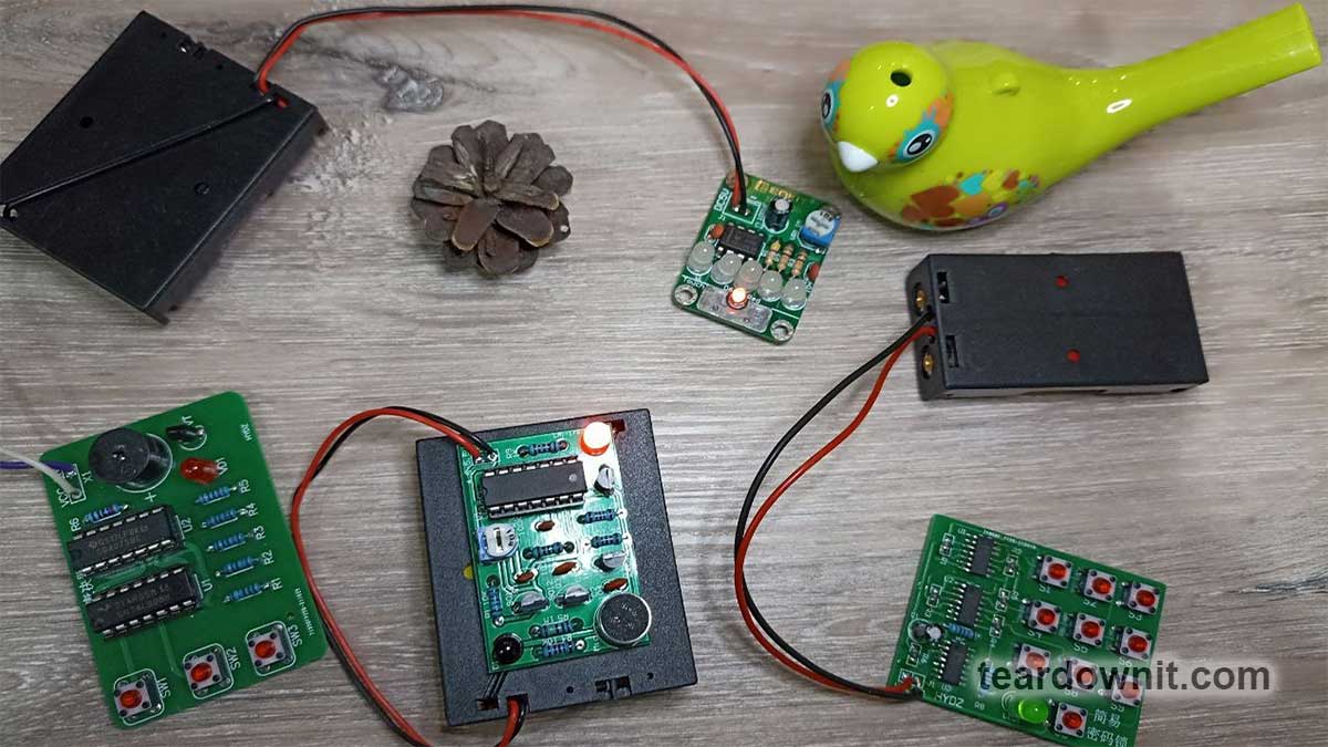
Nowadays, electronic DIY projects with microcontrollers, especially Arduino, are very popular. The microcontroller makes it easy to create many interesting and useful things.
I am even more interested in assembling different devices with simple logic circuits. They are easier to buy when there is a shortage of semiconductors, and they are not susceptible to software failures, hacking, and firmware corruption. And most importantly, their principle of operation is more visual, which gives me aesthetic pleasure.
Today I will introduce readers to four simple devices. Three of them are based on flip-flops, and the fourth one, which we will start with, could use a flip-flop.
Voting machine
The majority rule applies when people vote to accept or reject a proposal. The decision is made if more than half of the participants vote in favor.

If there are three voting participants, it requires two or all three to press the buttons to answer in the affirmative. This is the logic of this little electronic toy.
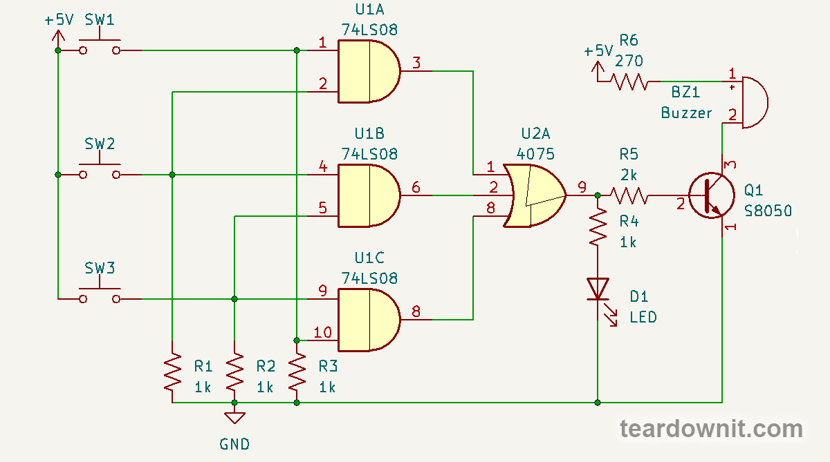
The 74LS08 chip contains four AND logic elements with two inputs. The output of each element will be 1 if 1 at both inputs. Otherwise, it will be 0.
The circuit uses three of four 74LS08 elements. The inputs of each one are connected to one of three possible pairs of buttons. They are pulled up to the ground with resistors, so the input will be a logical 0 unless the button that connects the input to plus power is pressed.
The CD4075 chip contains three OR logic elements with three inputs. The element's output will be a logical 1 if there is a 1 on at least one of the inputs or two or all three.
If any button pair is pressed, one of the inputs of the 74LS08 will be a logical 1, and the output will be a 1. The transistor will open, the buzzer will sound, and the LED will light.
In the case of an actual voting machine, it would be desirable to lock the button so that the voter does not have to hold it down. For this purpose, lockable buttons or toggle switches could be used.
Or you could use flip-flops - devices with two stable states that remember their state until a signal comes that changes this state.
Standby light with touch switch
But first, let's study a monostable multivibrator, aka a single vibrator. This device has one steady state, which exits under the action of the input signal, gives a certain pulse duration to the output, and returns to the steady state again.
This property can organize lighting in some small room or cabinet. The economical red LED consumes very little current and indicates the sensor location.
If you touch the sensor, the red LED turn off, but the five bright white LEDs turn on. Depending on the adjustment resistor, they will shine for a few seconds to a minute or two. After that, the white LEDs turn off, and the red LED turns on again.

The basis of this circuit is one of the most popular chips among DIY enthusiasts - the NE555 integrated timer.
The two main components of the NE555 timer are an RS flip-flop and two comparators. The comparator is essentially an operational amplifier, or rather an operational amplifier workmode.

When the voltage on the "+" input is higher than on the "-" input, the comparator output will have a high voltage level, i.e., almost plus power. And if, on the contrary, the "-" input voltage is higher than the "+" input, the output will be low - almost minus power. That is practically zero/ground because our power supply is unipolar.
The RS-flip-flop is a circuit with two steady states, a logical 1 and 0 at the output. The one on the S - Set input switches the output to a high state, and the one on the R - Reset input switches the output to a low state. Thus the flip-flop is a memory cell.
The NE555 timer inputs are high impedance, which allows you to connect touch buttons directly to them. A touch button is a metal plate, or a metalized surface on the board, as in our case, where you can touch it with your finger.

The touch of a finger on our sensor connects the capacitance and a human body inductance to pin 2 of the NE555 timer. The capacitor C1 protects this input from interference to prevent false positives.
The variable voltage induced on the human body at the high impedance input of comparator 1 will cause the comparator to switch between high and low logic whenever the instantaneous voltage value passes through a value equal to a third of the supply voltage.
One switch of comparator 1 to logical 1 is enough to set the flip-flop to 1. Pin 3 supplies plus power to the anodes of the bright white LEDs. They turn on, and the small red LED, which glows when its cathode is minus power, turns off.
At the same time, the transistor, the open collector of which is connected to pin 7, closes. This transistor is designed to discharge the time-setting capacitor C3. The capacitor starts charging through resistors VR1 and R2.
When C3 is charged to 2/3 of the supply voltage, comparator 2 will go into a high state, going to the reset flip-flop input. The C3 charging time, and consequently, the LEDs glow, depends on the VR1 resistance, which we can adjust, and is in the range of 3 to 130 seconds.
The transistor will open and almost immediately discharge C3. At output 3, i.e., the cathode of the red and the anodes of the white LEDs will be a logical 0. The white LEDs will stop shining, but the red one will turn on. And our standby light (red LED) will wait for the next touch of the sensor.
LED candle (nearly)

This electronic candle does not simulate the flame flicker, but you can turn it on with a lighter or match, and turn it off with a whiff, just like a real candle. The infrared photodiode responds not only to the flame but also to any household appliance IR remote control.
Here the flip-flop of the CD4013 chip is used in the already familiar RS-flip-flop mode. In fact, it is capable of more, as we will see next.

Transistor Q1 amplifies the signal of the infrared photodiode D1. With the trimmer resistor R3, which is the collector load of the transistor, the sensor sensitivity can be adjusted, and the capacitor C1 suppresses high-frequency interference.
The amplified signal comes to the flip-flop input S. The flip-flop goes into the state of logical 1, and our candle - LED D2 - lights up.
The LED is not connected directly to the chip output, although it could handle such a small current, but through an inverting DC amplifier based on the Q4 transistor.
It is inverting because the logical 1 at the base of the transistor turns into a logical 0 at the collector. The collector is connected to the LED anode, and with a logic 0 at the anode, current will flow through the LED.
The microphone signal is amplified by two transistors, Q2 and Q3. They form a pure class B amplifier, which means that when there is no input signal, both transistors are completely closed, and no current flows through them.
Class B audio amplifiers distort the sound signal very much, so class AB is used instead in audio equipment to save power and class A for quality. But in our current device, it is not required to play the audio signal but to generate a pulse on the R input of our flip-flop to turn off the LED when blowing into the microphone (blowing out the candle).
The positive pulse from M1 through C2 will open Q2. The minus relative to the emitter will appear at the Q3 base, a PNP transistor that opens just by a minus. On the open collector of Q3 will be a plus; this is just the low logic level that will reset the flip-flop and blow out the candle.
The combination lock

We promised to tell you more about the CD4013 chip, and this electronic lock uses its functionality.

The circuit is based on 4 synchronous D-flip-flops, i.e., the two chips. Each CD4013 contains two such flip-flops.
The data input - D - U1A is always a logical 1 because this input is connected to plus power. But the synchronous D-flip-flop passes the input state to the output only when it receives a clock pulse on the C-Clock input. The rest of the time, the flip-flop keeps the output state that it remembered earlier.
U1A receives the synchronization pulse from button S1. Next comes a flip-flops chain, transmitting a logical 1 to LED D1, the light of which means the opening of the lock.
Remember we said that the CD4013 output current is enough for the LED? Here the LED is connected directly to the output of the chip.
Flip-flops U1B, U2A, and U2B are synchronized by buttons S4, S7, and S9, respectively. Therefore the secret code is 1479. This is the sequence in which the buttons must be pressed to open the lock.
Buttons S2, S3, S5, S6, S0 reset flip-flops U1A, U1B and U2A. After pressing any of them, the code must be entered from the beginning. But they do not close the open lock because they do not affect the last flip-flop.
To close the lock, press the button S8, which resets the U2B, or the button S9. Because with the opening of the lock, the inverting output U2B through the logic inverter Q3A resets the previous three flip-flops. Pressing S9 will transfer a logic zero from the U2A output to the U2B output and close the lock.
The CD4011 chip contains 4 NAND logic elements. It would help if you connected all its inputs together to use the NAND as an inverter. The capacitor C1 protects the reset line of the flip-flops from false noise signals.
Discussions
Become a Hackaday.io Member
Create an account to leave a comment. Already have an account? Log In.