 teardownit
When servicing metal cable lines, measuring bridges are most commonly used. However, other devices are also available for locating cable faults.
Firstly, they provide high accuracy in a wide range of measured values.
Secondly, their use makes it possible to organize measurements in such a way as to compensate for extraneous influences, which is indispensable for fault location.
Thirdly, they are not expensive.
It will be helpful for the reader to become familiar not only with the construction of measuring bridges but also with the principles of their application for fault location. However, speaking the language of mathematics, such knowledge is necessary, but more is needed for constructing optimal measurement schemes. Diagnostics is always both an experience and an art.
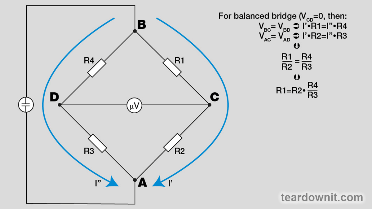
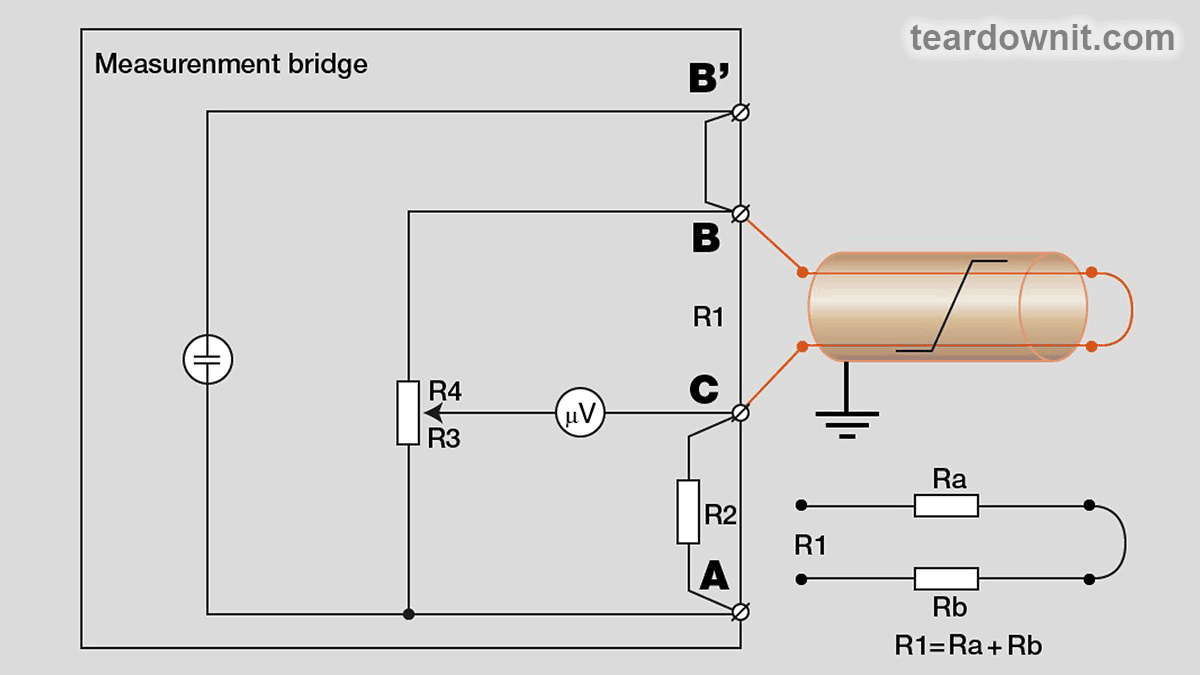
The principle of the bridge measuring circuit is shown in Pic. 1, and its application in practice is shown in Pic. 2. Resistance R1 is calculated based on the ratio R4/R3 obtained when balancing the bridge, and a resistor with a known value is used as R2. Of course, this gives only the most general idea of the measuring circuit of the bridge. In fact, it is much more complicated - modern bridges are based on digital processors. The microprocessor core allows automating the measurement procedure (in the first models, the operator had to use a calculator, today all calculations are performed by the hardware) to ensure the multifunctionality of the device (many bridges are integrated with other measuring instruments - multimeters, OTDRs, etc.), to eliminate interferences (foreign DC and AC voltages are almost always present on the cores of cables), to organize further processing of accumulated measurements (storage, exchange with the computer, printing and so on).
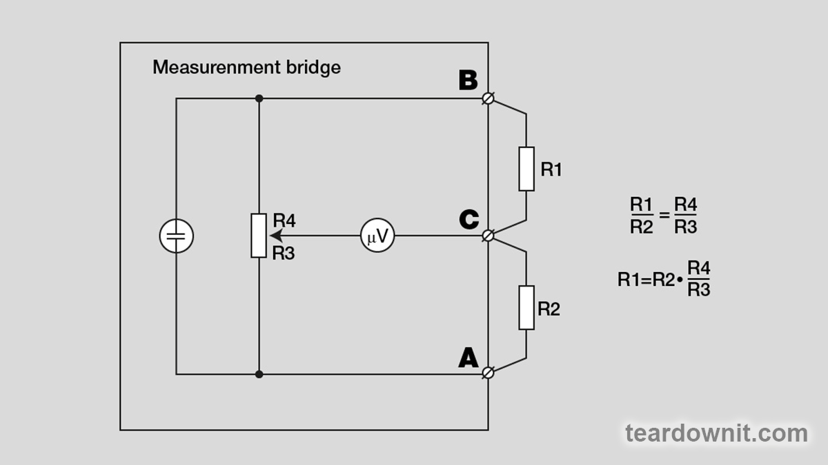
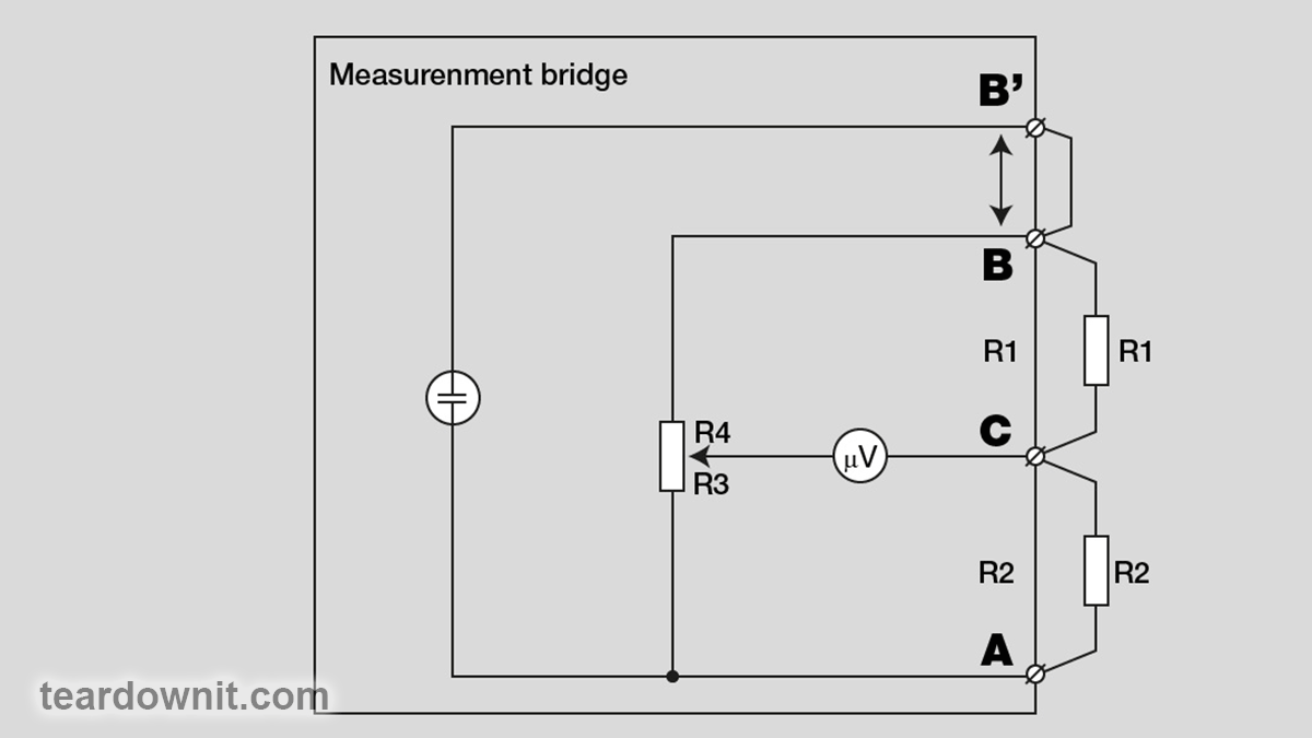
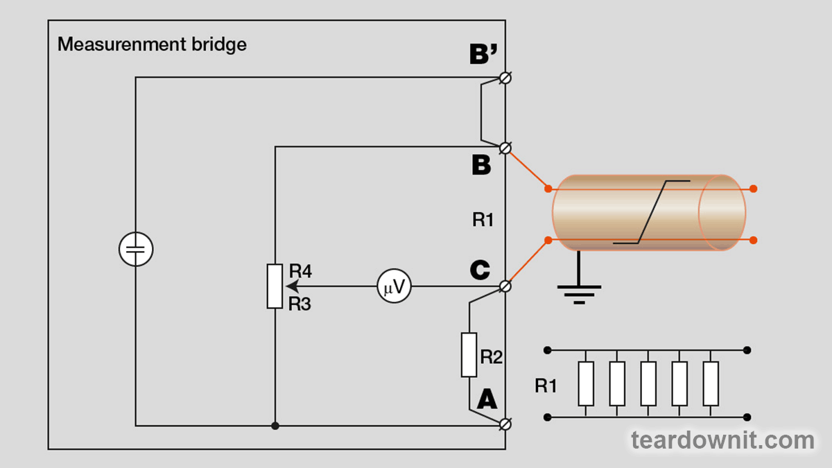
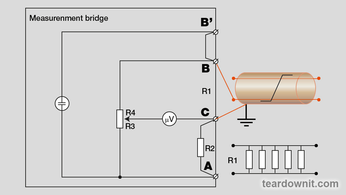
The bridge used for the resistance measurement discussed above is named Wheatstone. It uses only two terminals (B and C) to connect the circuits to be measured. Two other bridges, Murray and Kupfmuller, have more advanced circuits. Here the measured circuits are connected with three terminals (A, B, and C). The more complicated Hilborn/Graf schemes use four terminals (A, B, B' and C). Pic. 3. The meaning of increasing the number of connection points will become apparent when considering measurement schemes using bridges.
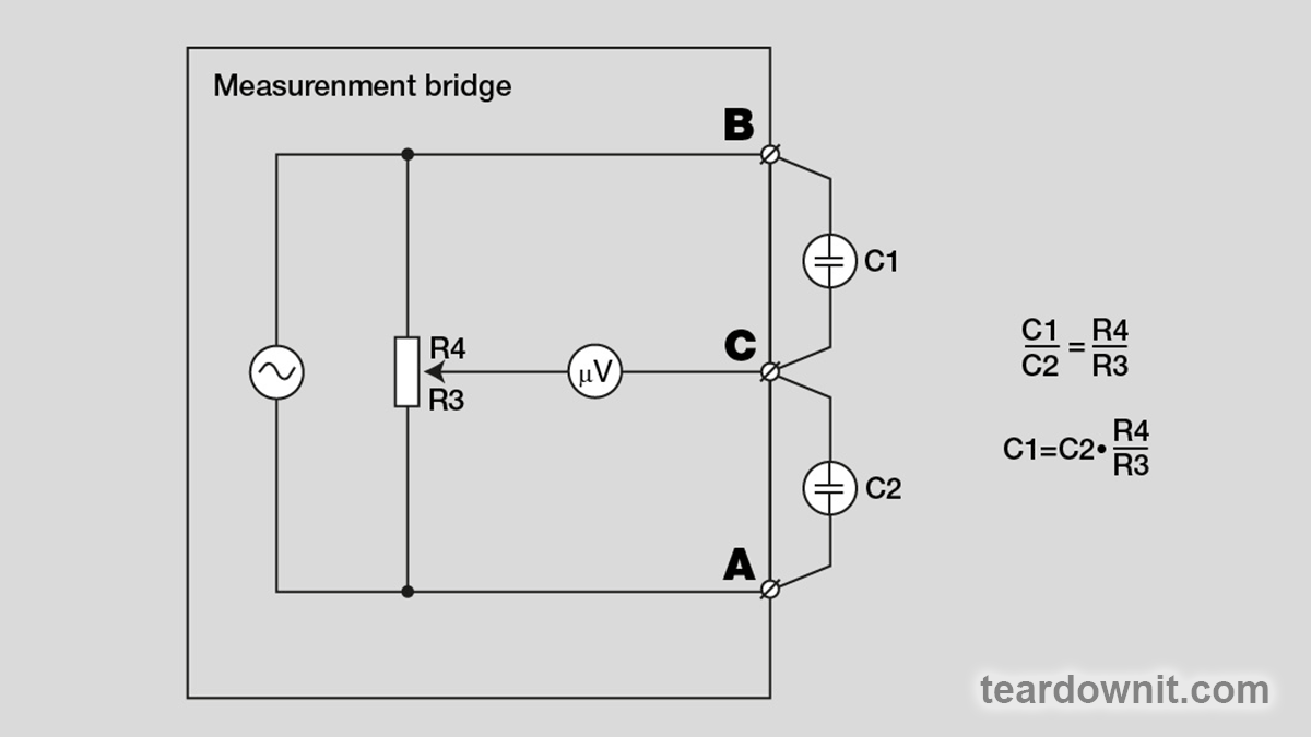
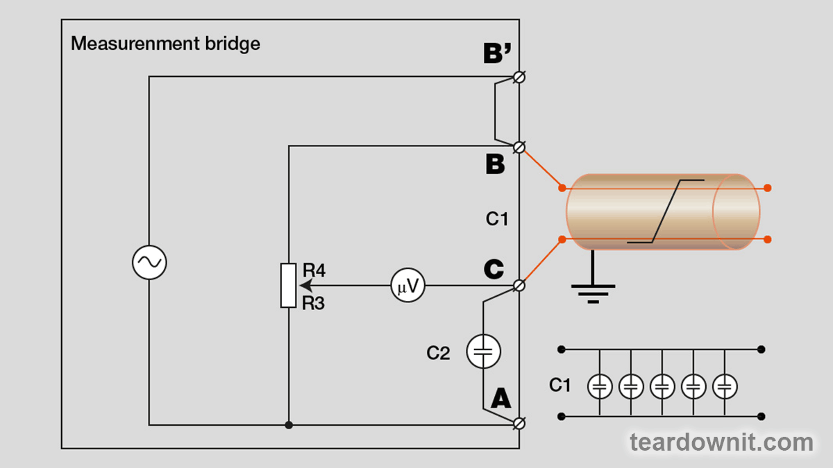
All described bridge circuits are used for measurements at direct current (values of active resistances connected to the terminals are determined). In addition, Wheatstone and Murray bridge circuits are used for measurements at alternating current (the values of capacitances connected to the terminals are determined). In such bridges, the voltage source is a sinusoidal voltage generator.
Now let's focus on the measurement schemes. Using the Wheatstone bridge at constant current, measure the resistance of the twisted pair (cable harness), the insulation resistance of the cores of the pair, and the insulation resistance between the cores and the shield ( Pic. 5, Pic. 6, Pic. 7). The values of the mentioned parameters are used to diagnose cable lines. Localization of faults requires the location of the fault on the cable line. Using a DC bridge, it is easy to calculate the distance to the fault location. Knowing the loop resistance Rwire and the cable core resistance R', you can use the formula: Lline = Rwire / 2 R' and calculate the length of the twisted pair.
Their cross-section determines the linear resistance of copper cores in a tabular method. It depends not only on the cross-section but also on their temperature. To avoid errors, you must use the resistance value for the corresponding temperature (it is crucial for overhead cable lines, where the temperature varies over a wide range). In simple bridges, the operator manually enters the values from tables. In more complex devices, an automatic or semi-automatic calibration procedure determines the correction factor from the measured temperature value (for which a probe sensor is supplied with the device).
The bridge method can also set the twisted-pair length with alternating current. In this case, the measured parameter is the capacitance of the twisted pair. Dividing the capacitance of the twisted pair by its total capacitance, we obtain the length of the twisted pair.
Similar to the above measurements at direct current, using the Whitston bridge at alternating current determine the capacity of the twisted pair (loop) and the capacitance of each of the cores of the pair relative to the screen, see Pic. 8. The length of the cores can be calculated from their capacitance per wire. A twisted pair's capacitance (nF/km) depends on the cross-section, type of twisting, type, and insulation material. It is determined by a tabular method according to the cable type. As a rule, a sharp increase in the capacity of a twisted pair compared to its nameplate value indicates the presence of water in the cable core. To localize this type of damage, other methods are used, first of all, probing the damaged pair with a reflectometer.
Note that, unlike resistance, the capacitance weakly depends on temperature, significantly simplifying measurements.
Discussions
Become a Hackaday.io Member
Create an account to leave a comment. Already have an account? Log In.