 teardownit
Are you the type of person who likes listening to good ol' radio like I do? Unfortunately, medium-wave broadcasting has decayed in the last few decades. There's nothing in many areas, even at night when medium wavelengths work best. That’s why the radios from our childhood stay unused and collect dust.
Today, we will make a small medium-wave radio transmitter that can help you check and configure AM radio receivers and listen to music through them if you connect an MP3 player or smartphone.
The power of this transmitter is 0.0005 watts, and the range is about 3 feet, so you won't disturb your neighbors or need a license for it.
The transmitter is AMT-MW207 and was developed by an enthusiast under the nickname "Radio Lover". The circuit is proven to work perfectly and stays unchanged, but the layout of the PCBs can be different. For example, here is the newest and perhaps most nice-looking version 1.3 revision 2, dated September 15, 2022.

I've assembled ver. 1.2 rev. 7. It has a green board, no frequency scale, and the wavelength adjustment knob is located at the very bottom of the board. I consider these differences to be purely aesthetic. The transmission frequency can be viewed much more accurately on the screen of a separate frequency meter or oscilloscope.
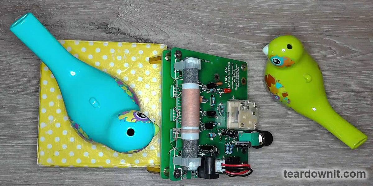
Older versions are less convenient to attach the testing hook of the oscilloscope to, and they have no cutouts in the back of the PCB for winding up excess wire. The differences are generally insignificant; all versions of the transmitter work and sound the same.
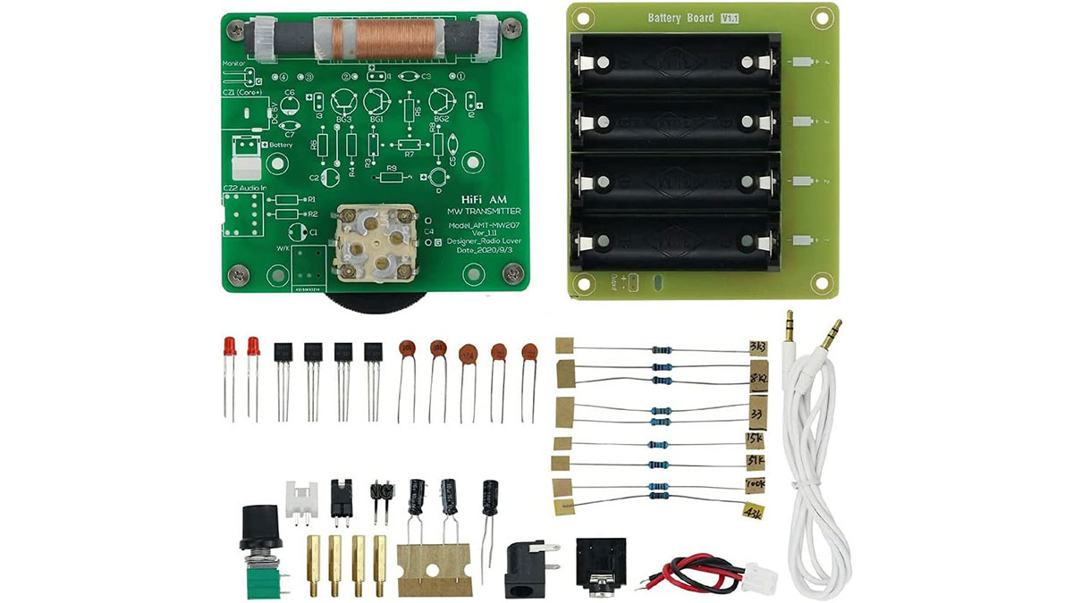
The DIY kit was designed and kitted with passion: brass fittings, high-quality AA battery holders, and neat resistor value markings.
The potentiometer volume knob was not forgotten either; they also got me a good 3.5 mm TRS-TRS cable. In fact, this is an important detail. You sure can twist the variable resistor's shaft without a handle. Still, you won’t be able to connect a player or a laptop if there is no connecting cable. You won’t be able to try out a freshly assembled device, which will ruin the mood.
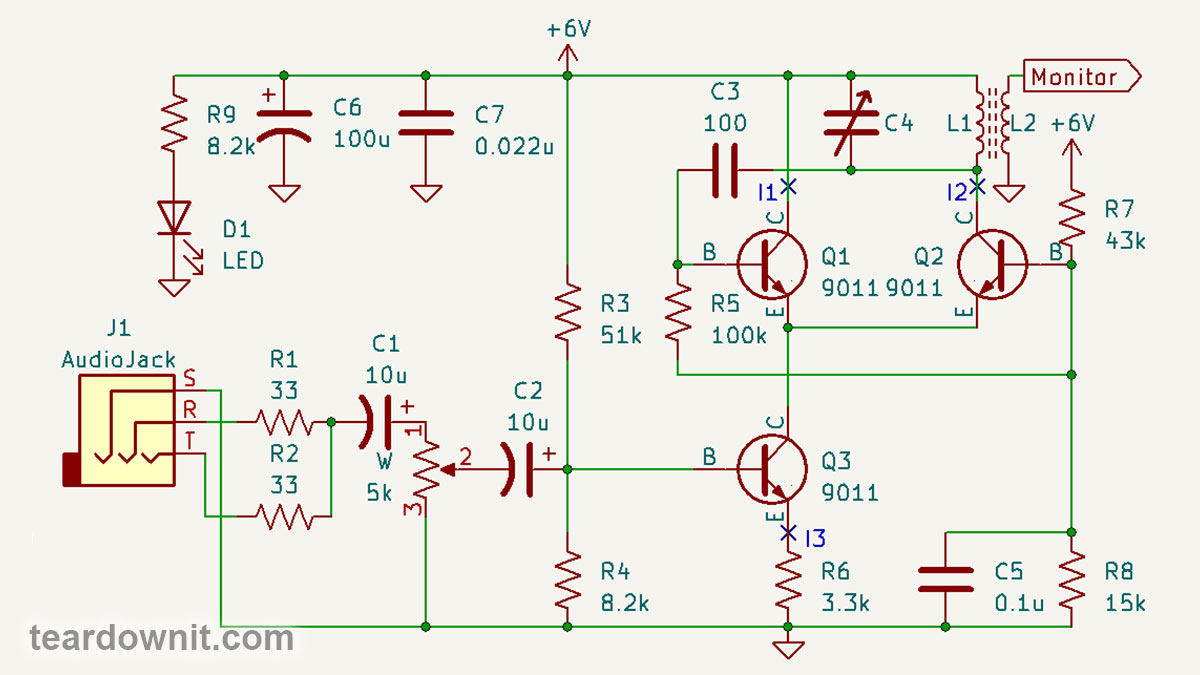
The transmitter circuit is simple yet elegant. Transistors Q1 and Q2 are a long-tailed pair, and Q3 is its current stabilizer.
A transistor current stabilizer is an emitter follower whose load is a resistor R6.
According to Ohm's law, the current through this resistor will be equal to the voltage across it divided by its resistance. The voltage at the emitter of a transistor connected to a circuit with a common collector is similar to the voltage at the base minus Vbe.
Vbe, the voltage between the base and the emitter for a particular transistor, is an almost constant value. Nothing is ideal, so Vbe actually depends on the temperature and base current, but these influences are tiny and can be ignored.
R3 and R4 together are a voltage divider. With a supply voltage of 6 volts, the current through this divider is 6V / (R3 + R4) = 6V / 59.2 kOhm = 101 µA. We neglect the base current of transistor Q3, which is connected in parallel with R4. I will explain why later.
The voltage at R4 is 101 µA * 8.2 kOhm = 828 mV. As Vbe = 0.63 V, resistor R6 gets the remaining 199 mV. Then, the current through it will be 60.3 µA.
The emitter current of transistor Q3 is the sum of its collector and base currents. The collector current is β times the base current, where β is the current gain coefficient of the transistor.
The average value of β for the 9011 transistor is 90. That is, the collector current is 60.3 µA * (β-1)/β = 60.3 µA * 89/90 = 59.63 µA.
The base current is 60.3 µA / β = 0.67 µA, less than 0.7% of the R3R4 divider current. Therefore, the base current can be neglected even in such a microampere case due to the fact that Q3 is connected as an emitter follower.
That is, it has a very high input impedance. It can even be calculated: Rin = Vin / Ib = 199 mV / 0.67 µA = 297 kOhm.
Even if our transistor has twice the current gain, β = 180, then the input resistance of such a stage with a common collector at an emitter current of 60 μA is twice as high and equals 594 kOhm.
So, the base current of Q3 is almost zero, and the collector current is almost equal to the emitter. The emitter follower has a high input impedance and can also serve as a voltage-to-current converter and a stable current generator.
This can be useful in many cases, for example, when powering LEDs. Or for generators of linearly varying voltage, their capacitors are charged with a stabilized current. Hence, the voltage across them increases linearly. In the era of cathode-ray oscilloscopes, such generators were used to deflect the beam horizontally.
In addition to the constant voltage from the divider R3R4, an audio signal is supplied to the base of transistor Q3. Identical resistors R1 and R2 mix stereo down to mono. Capacitors C1 and C2 let alternating current pass through and block direct current.
Potentiometer W regulates the amplitude of the signal. With the same voltage divider as R3R4, only the ratio of the resistances of the upper and lower branches can be changed by turning the knob.
So, transistors Q1 and Q2 form a differential amplifier. The total current of these two transistors, set by the current stabilizer on Q3 and modulated by the incoming audio signal, is redistributed between Q1 and Q2, depending on the voltage difference at their bases.
Collector Q1 is connected to the power supply positive terminal. Thus, the output of the differential amplifier is the collector of Q2, the inverting input is the base of Q2, and the non-inverting input is the base of Q1.
Resistors R7 and R8 set a constant bias for the bases of Q1 and Q2. Let's assume that the input impedance of each of the inputs of the differential amplifier is 100 kOhm.
Then, the current I1 will be twice as high as the current I2. After all, base Q2 is directly connected to the node between R5 and R7, and base Q1 base is connected through resistor R5 with a resistance equal to the input. That is, the base current, and therefore the collector current, for Q1 will be half as low.
We get a system of equations: I2 = I1 * 2; I1 + I2 = I3 = 60 µA.
The solution to the system of equations is I1 * 3 = 60 μA; I1 = 20 µA; I2 = 40 µA. These are precisely the reference current values that the author of the scheme mentioned in his explanations.
Older versions of the board, if you look closely, had jumpers for you to connect a multimeter as a microammeter and adjust the operation modes of transistors with trim potentiometers, which should be soldered in place of R3, R5, and R7.
However, judging by everyone's experience, these transmitters work perfectly with the included resistors and need no tweaking. Therefore, jumpers were removed from the new versions, but the holes for trim pots were left on the PCB.
The load of the differential amplifier is the LC resonant tank L1C4, and the output is connected to the non-inverting input through capacitor C3. The inverting input is grounded for alternating current by capacitor C5.
We have the Colpitts generator, which we've studied in the previous post! The only difference is that it is assembled not on one transistor but on a three-transistor differential amplifier.
C4 is a variable capacitor for adjusting the oscillation frequency, and L1 is a ferrite rod wound coil of the transmitting magnetic antenna.
The L2 coil connects an oscilloscope, frequency meter, or spectrum analyzer. You can also try connecting an external antenna to it to increase the transmission range. This won't help much because the operating currents of our transmitter are only tens of microamps, but it won't hurt either.
This transmitter sounds high-quality. Of course, you can clearly hear that this is an AM radio because this is indeed a real AM radio! The quality of FM transmission is much higher, which is one of the main reasons that it has replaced good old AM.
The sine wave on the oscilloscope screen looks nice at first glance. But if we look closely, we will see that the upper half-wave is slightly pointed, and the lower one is rounded and even a little flattened.
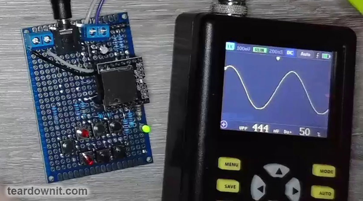
From an article about a homemade tube amplifier, we already know that such a waveform indicates a significant presence of the second harmonic and a small admixture of the third harmonic. For a powerful transmitter, this would be bad, but for a compact one, it is fine.

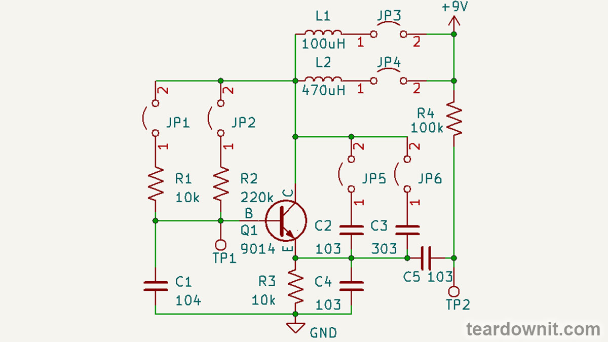
By the way, the eight-transistor superheterodyne in the video is also a DIY project. If you are interested, I can write another post on this and my other radios with a detailed description.
Discussions
Become a Hackaday.io Member
Create an account to leave a comment. Already have an account? Log In.