 teardownit
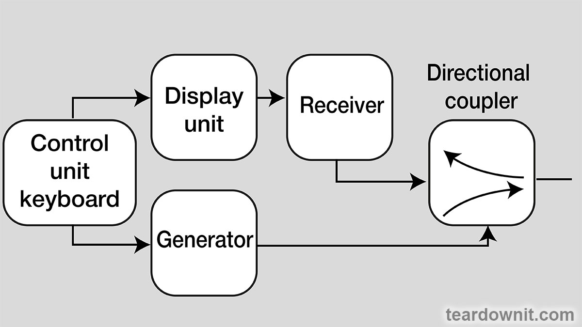
The general principle of operation of the reflectometer is elementary: a probing pulse is transmitted from the generator through a directional coupler to the cable; it is then partially (or completely) reflected back from impedance irregularities along the cable length. The reflected impulse arrives at the input of the device and, through a directional coupler, enters the receiving unit. This input signal is converted into digital format and shown on the display as a reflectogram; its form can be easily traced back to the known diagrams. Impedance abnormalities can be caused by various cable faults or external causes, like an incorrect plug-in.
 For successful direct fault detection, two parameters are of particular importance. First is the maximum distance to the damaged spot when it can still be clearly identified. The second is the accuracy of determining the defect.
Unfortunately, it is difficult for any manufacturer to comprehensively answer these specs because reflectometers can be used to test many different types of cables, primarily in real-world conditions rather than in a dedicated lab. Therefore, usually, device manuals contain a list of basic technical parameters.
Key values predetermining reflectometers' maximum detection range and damage detection accuracy are the amplitude and duration of the probing impulse, as well as the amplifier's sensitivity.
The Pulse
Most reflectometers are able to generate probing pulses of various durations. Short pulses allow one to detect a faulty spot relatively close to the point of connection of the reflectometer; they also provide better search resolution, meaning it's possible to detect two individual damage points close to each other. Longer impulses help find remote faults in the cable as they carry more energy. However, the search resolution in this case is decreased.
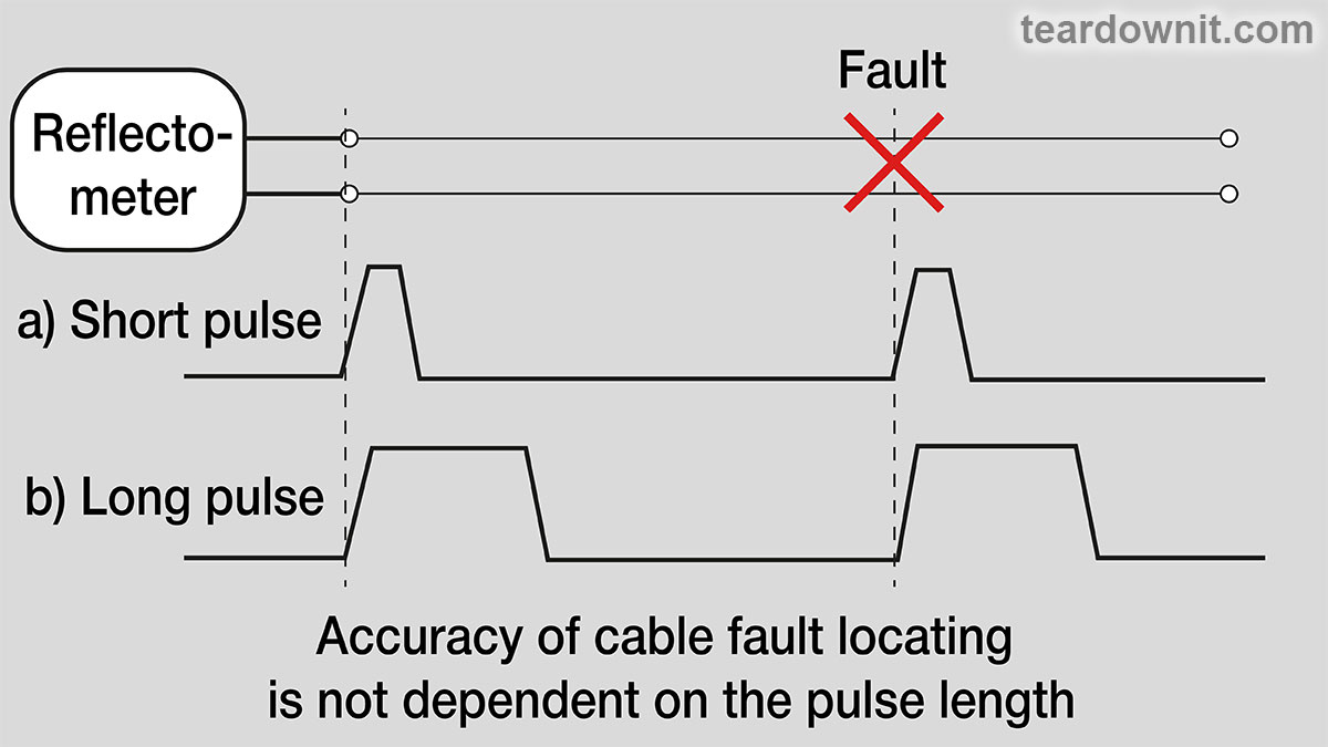
It is a common misconception that decreasing pulse width necessarily results in increased accuracy. This is not entirely true. When using a reflectometer, the measurement is made along the edge of the pulse. Therefore, if the primary purpose of the test is to detect just the first fault, the pulse duration has virtually no effect on the accuracy of the pulse edge measurement.
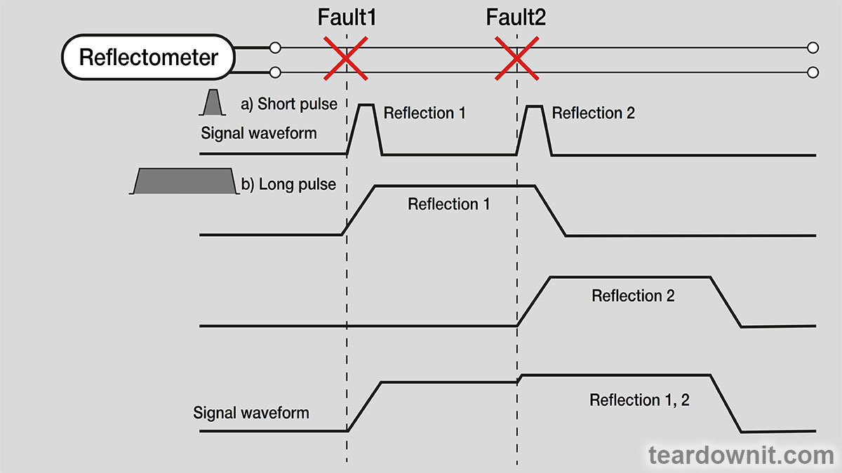
The main advantages of a short pulse are the narrowing of the so-called "dead zone" following the transmitted pulse and a corresponding improvement in resolution when detecting faults. The easiest way to explain the "dead zone" effect is by using the example of searching for two closely located damage points. Comparing graph shapes on the display for shorter and longer pulses, we'll clearly see that short pulses make both spots identifiable. But as the pulse width increases, the two spots become indistinguishable, as the dead zone covers the second one.
The same logic applies to the case when the fault is too close to the connection point of the reflectometer: the initial pulse, due to its width, will mask the one reflected from the nearest damaged spot. Some OTDRs use balance adjustment to fix this issue. It allows one to effectively suppress the transmitted signal and display just the one reflected from a fault located too close to the device. Thus, it is not that necessary to use short pulses to detect defects up close. Using longer pulses provides another advantage; the never-ending problem of mitigating signal noise can be dealt with by increasing signal energy and, therefore, improving the signal-to-noise ratio.
If the reflectometer you currently have does not offer the ability to send short pulses and, moreover, there is no balance adjustment, then to detect damage up close in the cable, we can suggest a simple trick: you can connect a short piece of cable between the reflectometer and the cable being tested; this will allow you to "move" the damage point further away from the device. Just remember to use the same impedance cable as the one tested. And to minimize spurious signal reflections, the device's total resistance must match the extension cable's resistance.
And one more thing to consider in practice: the reflectometer kit may include cables and adapters for testing particular types of cables. Those accessories must be used; always connect to a coaxial cable with a coaxial adapter, to a twisted pair — with twisted pair cable, etc. In addition, when checking twisted pairs, do not untwist them; such cables should not have separated straight wires longer than half an inch.
When assessing the pulse characteristics, you should pay attention to the following, although these specs are usually listed by the manufacturer:
• the pulse amplitude must be specified for Zo, i.e., with a load impedance equal to the total output impedance of the device. The amplitude when working on an open circuit will be twice as large (but you cannot use this assumption in practice!);
• the amplitude must be given for all pulses; often, the shorter pulses have a smaller amplitude than the rest;
• if possible, use an oscilloscope to check the duration and amplitude of pulses at the reflectometer outputs, especially in the case of the shortest pulses.

It makes sense to mention that the amplifier and sampling system of the reflectometer are not always capable of displaying very short pulses. However, some reflectometers can generate and output them. It's elementary to check; simply connect a resistor with a value of Zo to the output terminals of the reflectometer and then measure the pulse duration at half amplitude using the reflectometer cursors. If the device has a balance adjustment, it's the best time to use it to get a clear pulse.
The Amplitude
The distance the reflectometer can detect damage depends on the pulse amplitude (assuming a fixed pulse duration): the greater its value, the farther the reflectometer "sees." However, a huge amplitude value can lead to the measuring device distorting the actual characteristics of the line, which will complicate the process of finding faults.
The optimal impulse amplitude depends on the reflectometer's expected application. For telephone lines, 20 V is enough; for power cable testing using the arc method, high-voltage pulses can reach 25 kV.
In the latter case, the reflectometer simultaneously transmits high-voltage and probing impulses to the defected pair. An electric arc is formed at the damaged spot and is sustained for a certain duration. This arc short-circuits the high impedance point, allows the probing pulse to be reflected back from this spot, and allows the damage location to be clearly seen on the reflectogram. Two reflectograms are compared, with and without high-voltage pulses, to facilitate the search for a defect.
Discussions
Become a Hackaday.io Member
Create an account to leave a comment. Already have an account? Log In.