 Rob Ward
Programming 2764 EPROM with a Mega2560, SD card reader and 5-12V Buck converter
If you have ever wondered what it would be like to have a real retro -computer-nerd experience, then maybe programming EPROMs will fit the bill for you. Since the late 60's there were many and varied EPROMs sold, with different specs, but had better and easier programming procedures as time went on. Many had mysterious 3 lots of power rails early on (+5V, -5V and +12V), and with even more arcane requirements for Burning. The other factor was various manufacturers required different voltages on different pins and different timings for the same size memories. (Why "Burning"? Because many early EPROMs required 21V or 25V as a programming voltage, and it also had a great mental image of applying this voltage to a precious chip and BURNING the bits in, exciting!!! And conveyed the risk of what would happen if we got it wrong!!!).
When I wanted to add an 8kb EPROM to my SYM-1 project I was not optimistic this would be easy. However, boldly going where no other hackers had gone before me, I struck out to simplify things and make it possible to do some EPROM programming with minimal new purchases. I found out all one needed was a Mega 2560, a 28pin Socket (preferably ZIF, but not essential), a Mega 2560 shield, an SD card adapter, 5-12V buck converter (or some other static 12V power supply), and a single throw double pole switch. Some LED indicators can be added for the nervous Hackers who like to test things and feel comfortable things are happening properly. Essentially (and amazingly) things that can be found in the average spare parts (reuse?) bin these days.
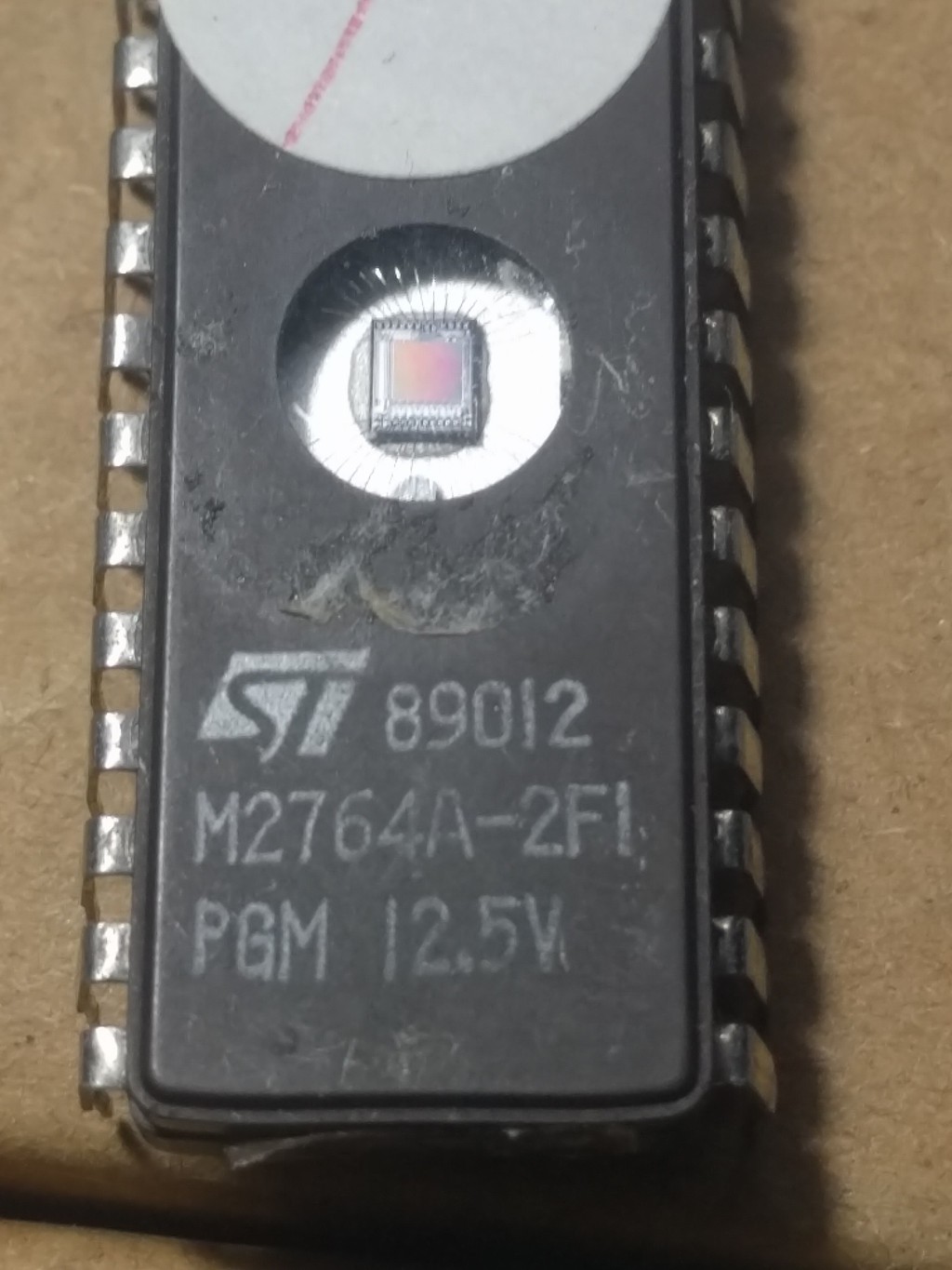
Below is the type of 2764 I have found has worked. Now, a warning, these things are produced in batches and I may have just been extremely lucky and found this system works on the only one or two chips in the known universe. However I have ordered from three different sources and they all work, so I feel confident some people will experience some success, in fact most people will experience total success. The EPROMs I have programmed 2 years ago are still working fine and have no errors. If you do not need 8Kb, then tie a few address lines low and just use part of it (they are so cheap, who cares?). You get the convenience of low cost Hacking, and a workable solution.
**** Download the EPROM Burning Program ****
And the physical setup looks like this with the Mega 2560 below, shield on top with 28Pin ZIF socket, 5-12.5V buck converter (adjustable to 12.5V) and a single throw double contact switch (plus a few optional indicators LEDs).
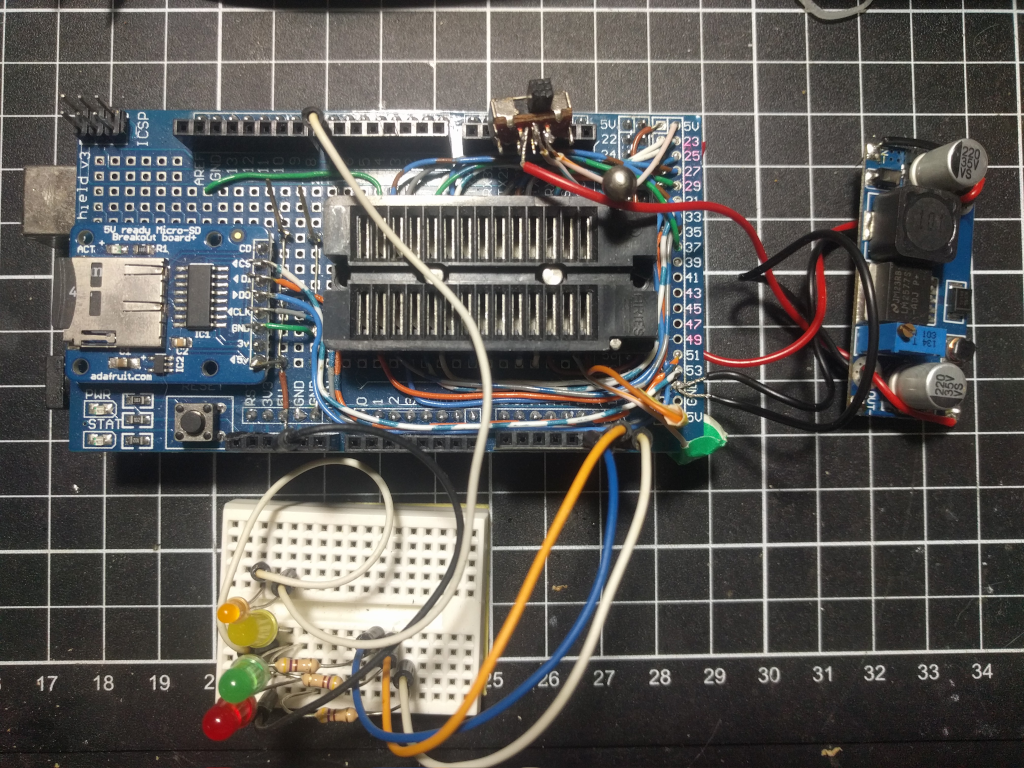
The wiring gets a bit messy on the shield board, but can be done. If you want to use one of the shields with a prototyping board (see the one above where I have added the indicator LEDs, it came with the Mega2560 prototyping shield. Search eBay with "Arduino Mega 2560 Prototype PCB Shield with LEDs Reset Switch + Mini Breadboard") then the pins can be connected (note a double width dual in line socket would need to be added to the RHS board of the shield to facilitate the plugin wires) with the usual prototyping "plug and play" connectors. The big advantage of this idea is that many ROMs/EPROMS and even EEPROMs could be accommodated by moving the wires around and writing your own software building/improving on my work.
Looking at the connections I found to work to Burn the 8kb EPROMs, so we are are looking to Burn 2764's
   Port  MegaPin Vpp   1         28 Vcc      Port Mega PIN
    K    12      A12   2         27 !PGM     K     15
    A    29      A7    3         26 NC       Vcc
    A    28      A6    4         25 A8       K     8
    A    27      A5    5         24 A9       K     9
    A    26      A4    6         23 A11      K     11
    A    25      A3    7         22 !OE      K     13
    A    26      A2    8         21 A10      K     10
    A    25      A1    9         20 !CE      K     14
    A    24      A0   10         19 D7       C     37
    C    30      D0   11         18 D6       C     36
    C    31      D1   12         17 D5       C     35
    C    32      D2   13         16 D4       C     34
    0V                14         15 D3       C     33
The Mega2560 has plenty of data I/O ports and many of them available in 8 bit wide chunks. This makes covering all the pins of a 28 pin 2764 8Kb EPROM quite easy. This implementation of an EPROM for the 2764 is quite a hack as my design only requires a single 12.5V source, hand switched, to program the chips. (This chip requires 6V when programming.)
Disclaimer: This programming software and advice comes with no guarantees or warranties and anyone who uses it should know that no responsibility will be taken by me for any loss or damage caused by following the instructions on this page. Using a chip in an out of spec way like this may or may not work with your batch of chips, your mileage may vary.
The above connection diagram shows what pins from the Mega2560 should connect to on the socket the 28pin EPROM is in. Those of you familiar with EPROMs will recognise many familiar pin positions. However these pin functions change positions depending on the size of the EPROM and the manufacturers. So a big warning, this program does not automatically map pin functions when a ROM/EPROM size is chosen from the menu list. All it does, is set the range of addresses the program with progress over. If you are not using a 2764 then you will need to either re-hardwire the connections or set up some sort of a plug board to connect the target ROM pinouts with the logical Mega2560 address emulating pins.
Burning the EPROM
The programming algorithm uses a search function to find out how many programming pulses might be required to turn all the 1 bits in a byte to a 0, and then does it twice over again. (NB When an EPROM is erased all the bits are 1's, so the Burning algorithm need only worry about the 1 that have to go to zero in any one byte.) So the threshold is exceeded by 300%. It also sets a reasonable maximum number of programming pulses that it quits on, ie if that byte has taken too many pulses, and it flags it as a bad byte. This is reported back to the user as the Burning progresses. Again the choosing the size of the memory from the menu does not auto set these for different types of memory (other than the 2764 as shown above). Adding these extra sophisitcated options are left to the ardent hacker.
The program has rudimentary file handling to Burn an EPROM image from a file on an SD Card to a 2764, or to dump a ROM/EPROM to a file on an SD card. First the file must be selected (the user will be warned if loading it and it does not exist). This filename can be operated on after that eg saving a ROM dump.
So with swapping the Mega2560 address lines to other pins on the ZIF-socket then other ROMs and EPROMs can be downloaded and preserved onto modern media. really old EPROM/ROMs may need more than +5V to power them. The best bit is ROM images from the Internet can be downloaded to an SD card and burnt to the EPROM.
There is a pin that Toggles on and off with the Burning command and could be used to automatically apply the 12V to the Vpp 2764 pin D7 (either with a relay or a "H" driver). However in the spirit of true Hackster-ing I chose to simplify matters and just a STDP switch to apply either 5V or 12V to pin D7 when programming. The 12V can be left connected apparently, but if Vpp is connected to 12V when the rest of the EPROM is 0V and you remove the chips, results are likely to be highly unpredictable!!
The Burn option in the program prompts when to manually throw the 12V switch on and later when to turn it off. Here is the simple menu program that runs completely in the Arduino IDE Terminal. It has a number of 8Kb images and some other files listed. I simply enter "6" and enter, and choose 2764 for an 8Kb EPROM, and that means the program will progress across 8Kb of memory addresses. I would only use the smaller memory options now if I have changed the Mega2560 connections to the memory chip involved. I have copied all my smaller memory chips I own to the SD card now and I am only interested in writing the 2764s. This is the most useful EPROM size for me at the moment.
********************************
*      EPROM Programming       *
* 5V, 24/28Pin, 2716,2532,2764 *
********************************
Initializing SD Filing System...OK!
Current files:..
Z_GPS.CSV 44544
EPROM17.BIN 8192
EPROM18.BIN 8192
EPROM19.BIN 8192
EPROM23.BIN 8192
BAS_C000.BIN 8192
RAE_8KB.BIN 8192
RAE_B000.BIN 4096
RAE_E000.BIN 4096
SYM1-1.BIN 4096
'''''''''''''''''''
1. 2716    2k EPROM
2. 2732    4k EPROM
3. 2532    4k EPROM
4. MOS ROM 4k   ROM
5. MOS ROM 8k   ROM
6. 2764    8k EPROM
Which size EEPROM To use?
This presents the following main menu.
..................................
EPROM/ROM Reader/Copier/Programmer
''''''''''''''''''''''''''''''''''
Nominated filename: No File.??. (No such file)
EPROM2764 Memory size 0x2000 bytes
 S  Choose Size of EPROM/ROM
 L  List SD Files
 F  Choose a File name
 I  Inspect an Image file in HEX
 E  Check for Erasure
 B  Burn File to a ROM
 C  Compare a ROM against a File
 D  Dump ROM in HEX and ASCII
 G  Get a ROM into a File
 T  Test OE/EN/PP Pins
Which Function?
These functions are pretty self explanatory and allow the usual operations of using a preloaded EPROM image from the SD Card, then checking the EPROM is erased, Burning the EPROM and inspecting the contents of the EPROM and comparing the contents of the burnt EPROM against the nominated SD Card file.
There are also indicator LED's attached to the Mega2560 that can be used to indicate the control signals for Output Enable, Chip Enable and Programming Pulse. These are activated when a ROM is accessed, either for reading or Burning or comparison, and can give reassuring flickers that all is going well. An LED to show when the Programming Voltage is applied is also a good idea.
  //  plus Chip Enables        Mega Pins A14,A13   !CE !OE (!G)        Port K  0x11100000
  //  plus Programming pulse   Mega Pin  A15       !PP
  //  plus Programming Voltage control   D7        Vpp
A simple 5V to 12V buck converter running off the 5V Arduino rail works quite well.
The program is pretty well documented, though others may disagree. It contains information on other common ROM/EPROM pinouts if you are wanting to adapt it to rescuing or programming chips other than 2764s. The programming style gets 5.5/10, where 5 is a pass, ie it works.
Anyway I offer the ideas to the world and hope people with find it useful as it is or improve on it. It should make the idea of using an EPROM in a retro-computer build more attractive and maybe a lot of more authentic fun. By the way I still the use the original Germicidal UV lamp (search eBay "5 Watt UV Germicidal Bulb G23") for similar one I sourced 40 years ago for erasing the EPROMS. There maybe more moden UV LED qalmps that will work as well.
A really clever person should be able to adapt the program to burning EEPROMS as well with the basic structure shown above. I would love to hear from you.
Cheers, RobW
Discussions
Become a Hackaday.io Member
Create an account to leave a comment. Already have an account? Log In.
Yes, just a bit of "hacker good luck" (we do have it from time to time), but I avoided all the other fancy level shifting on the other pins, eg Vdd to 6V etc. If the same chips as mine are found on eBay, and they are plentiful, then your project is good to go. Most people will read many types of EPROMs to find material, but in their own designs will settle on one type, probably like me for one SBC setup. 8kb is a good size for 8bit hackers.
Are you sure? yes | no
I have a photo here of one of the EPROMs I have been using. I clearly shows 2764 and 12.5V and I know it is an 8Kb device. It works. I will include it now in the article.
Are you sure? yes | no
Perhaps the Natsemi 27C64Q? Or maybe the Microchip 27C64. I have some of those, as well as the earlier 2764s requiring higher voltage. I'm not doubting you have a 12.5 V EPROM. I'm just saying that the 2764 designates more than one generation of technology. BTW, isn't 5V -.> 12V a boost converter?
Are you sure? yes | no
I think you are lucky you had a 2764 that can be programmed with a Vpp of 12.5V. Other models of 2764 require higher voltages.
Are you sure? yes | no