 danjovic
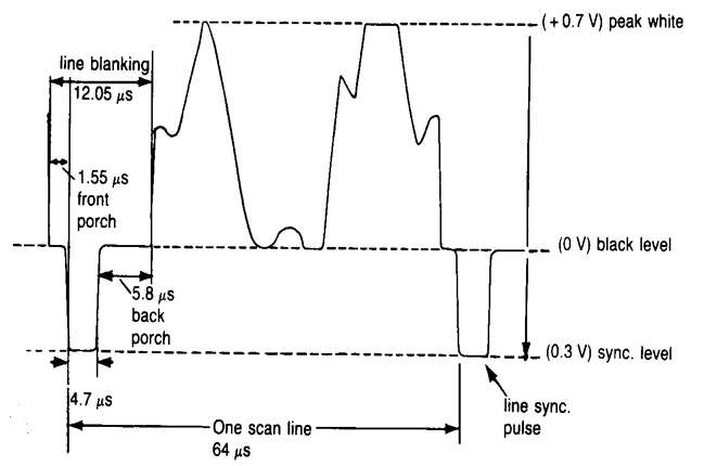
Composite video standard defines a signal with 1Vpp amplitude under a 75 Ohms. From that signal 70% (0.7V) is the amplitude of video information which stands above a 0.3V pedestal, while the synchronism information (sync tip) corresponds to the remaining 30% of the total amplitude or 0.3Volts below the pedestal.
Many projects of video generation for microcontrollers provide video signals that may work but don't respect the video standard, thus the signal generated might not be properly displayed depending upon the monitor used.
But generating a video signal with correct amplitude and impedance can be easily accomplished with the aid of resistors and some math.
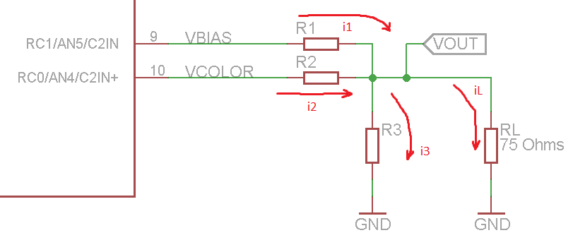
Consider the circuit topology below where pin named VBIAS generates Sync signals, while VCOLOR pin generates video signals.

With two pins for generating the Sync and Video information we can have four possible combinations from which only three are expected: Sync level, Black (pedestal) and White Level.
We need then to calculate the value of the resistors wich can provide the following voltages
Black Level    0.3 Volt @ 75 Ohms
White Level    1.0 Volt @ 75 Ohms
Sync Level       0 Volt @ 75 Ohms
First thing to consider are the Voh and Vol from the microcontroller. Taking a PIC16F688 as example such levels can be in the range from VDD-0.7Volts to Voh and 0.6Volts to Vol. It means that our Sync level might be slightly biased to 0,3Volts under 75 Ohms load (0.6Volts without load).

Our amplitudes must then be corrected to compensate for the biased Sync level while maintaining the total amplitude in 1Vpp
Black Level    0.6 Volt @ 75 Ohms
White Level    1.3 Volt @ 75 Ohms
Sync Level      0.3 Volt @ 75 Ohms
Considering the resulting internal impedance of 75 ohms such values shall be doubled when no load is present.
Level   VSync  Vvideo  Vout(@75R)  Vout(no load)
Black   4,7V   0,6V    0,6V        1,2V
White   4,7V   4,7V    1,3V        2,6V
Sync    0,6V   0,6V    0,3V        0,6V
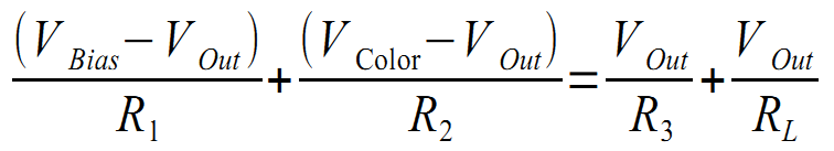
Now we have the necessary information to calculate the resistors. Let us use Kirchoff's current law: “At any node (junction) in an electrical circuit, the sum of currents flowing into that node is equal to the sum of currents flowing out of that node”
Then we have

Considering the voltages involved we have now the generic circuit equation:
Let us use Conductance instead of Resistance to make the math easier to deal with

Then for RL=75Ohms, VOL=0,6Volts e VOH=4,7Volts (PIC Vdd @ 5,4Volts) the equation for the three possible video levels are:

On the absence of load, RL = infinity, which means the Conductance is zero. Then we have the equations for the unloaded circuit.

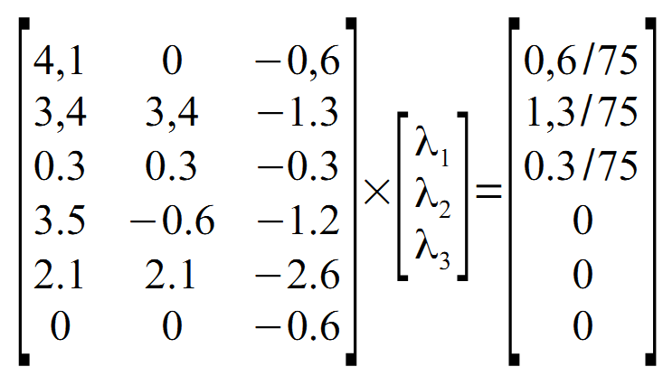
The 6 equations can be written as a product of matrices
Using Scilab we can easilly get the resulting conductances.
>A=A={4.1 0 -0.6 ; 3.4 3.4 -1.3 ; 0.3 0.3 -0.3 ; 3.5 -0.6 -1.2 ; 2.1 2.1 -2.6 ; 0 0 -0.6}
>b=[ 0.6/75 ; 1.3/75 ; 0.3/75 ; 0 ; 0 ; 0 ]
>x=A\b
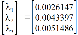
Which can be converted to resistances, resulting in
>x.^-1

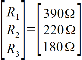
Then using the most close commercial values we have:
Let's now do the oposite way and check which are the theoretical values we can achieve using commercial value resistors. Rewriting the equations in terms of Vout we have:

Then solving for the possible output levels we have:
Level   Vsync  Vvideo  V Out(@75R)  V Out (no load)
Black    4,7    0,6       0,64         1,29
White    4,7    4,7       1,35         2,71
Sync     0,6    0,6       0,17         0,35
Let us now estimate the
output impedance by the ratio of voltages with and without the 75
Ohms load.
Vopen/Vload = 2,71/1,35 = 2,01
Then from Thèvenin:
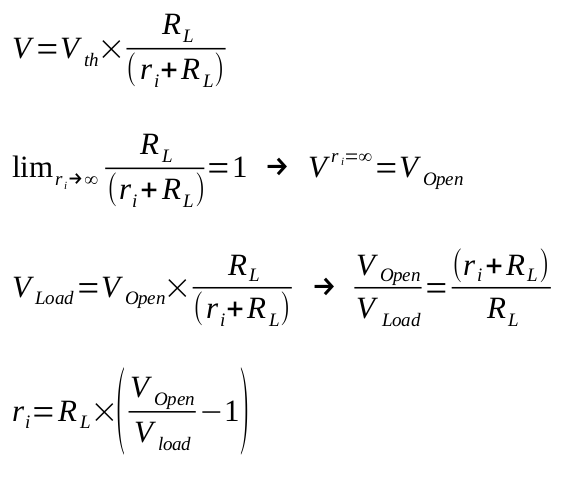
In plain numbers we have ri=75 * (1,01) = 75,75 Ohms. Good enough!
The figure below shows the circuit with final values.
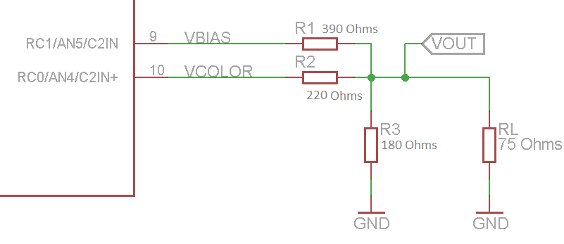
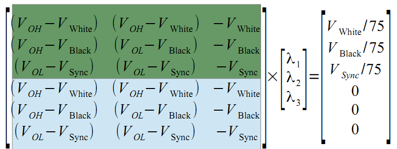
For calculating the resistor values for other microcontrollers and logic gates (TTL, CMOS) it is possible to use the general matrix system below. The green lines correspond to the voltage levels with 75Ohms load while the blue lines are the voltages with open circuit (no load).
In Scilab, it is possible to use the equations below:
Voh = 4.7
Vol = 0.6
Voffset = 0.3
Vwhite = 1.0 + Voffset
Vblack = 0.3 + Voffset
Vsync  = 0.0 + Voffset
V = { 	(Voh - Vwhite) (Voh - Vwhite) -Vwhite ; (Voh - Vblack) (Vol - Vblack) -Vblack ; (Vol - Vsync ) (Vol - Vsync ) -Vsync  ; (Voh - 2*Vwhite) (Voh - 2*Vwhite) -2*Vwhite ; (Voh - 2*Vblack) (Vol - 2*Vblack) -2*Vblack ; (Vol - 2*Vsync ) (Vol - 2*Vsync ) -2*Vsync  }
I = { Vwhite / 75 ; Vblack / 75 ; Vsync / 75 ; 0 ; 0 ; 0 }
s = V\I
r = s.^-1
Notes:
It is necessary to notice that the pins that drive the resistor must me able to source and sink currents around 25mA, which many microcontrollers can handle. On devices with less capacity the use of a buffer is recommended.
This circuit topology and calculations have been used in the following projects:
Discussions
Become a Hackaday.io Member
Create an account to leave a comment. Already have an account? Log In.
That's odd because I pasted the commands in your post on scilab and it worked for me yielding the same results as in the article.
btw, considering a PIC16F688 powered with 5V, Voh = Vcc-0.7V =4.3Volts, and a Vol of 0.6V the values are
r =
352.60106
204.96357
215.36507
Are you sure? yes | no
I was very interested in this topic and I am glad that it was described so well. Unfortunately, after entering the commands introduced here into SciLab, I got an error. I have read and checked and I will give you how they should look like.
1. Specific example for PIC microcontroller:
A=[ 4.1 0 -0.6 ; 3.4 3.4 -1.3 ; 0.3 0.3 -0.3 ; 3.5 -0.6 -1.2 ; 2.1 2.1 -2.6 ; 0 0 -0.6 ];
b=[ 0.6/75 ; 1.3/75 ; 0.3/75 ; 0 ; 0 ; 0 ];
x=A\b;
x.^-1
2. General example:
Voh = 4.7;
Vol = 0.6;
Voffset = 0.3;
Vwhite = 1.0 + Voffset;
Vblack = 0.3 + Voffset;
Vsync = 0.0 + Voffset;
V = [ (Voh-Vwhite) (Voh-Vwhite) -Vwhite ; (Voh-Vblack) (Vol-Vblack) -Vblack ; (Vol-Vsync) (Vol-Vsync) -Vsync ; (Voh-2*Vwhite) (Voh-2*Vwhite) -2*Vwhite ; (Voh-2*Vblack) (Vol-2*Vblack) -2*Vblack ; (Vol-2*Vsync) (Vol-2*Vsync) -2*Vsync ];
I = [ Vwhite/75 ; Vblack/75 ; Vsync/75 ; 0 ; 0 ; 0 ];
s = V\I;
r = s.^-1;
r
Are you sure? yes | no