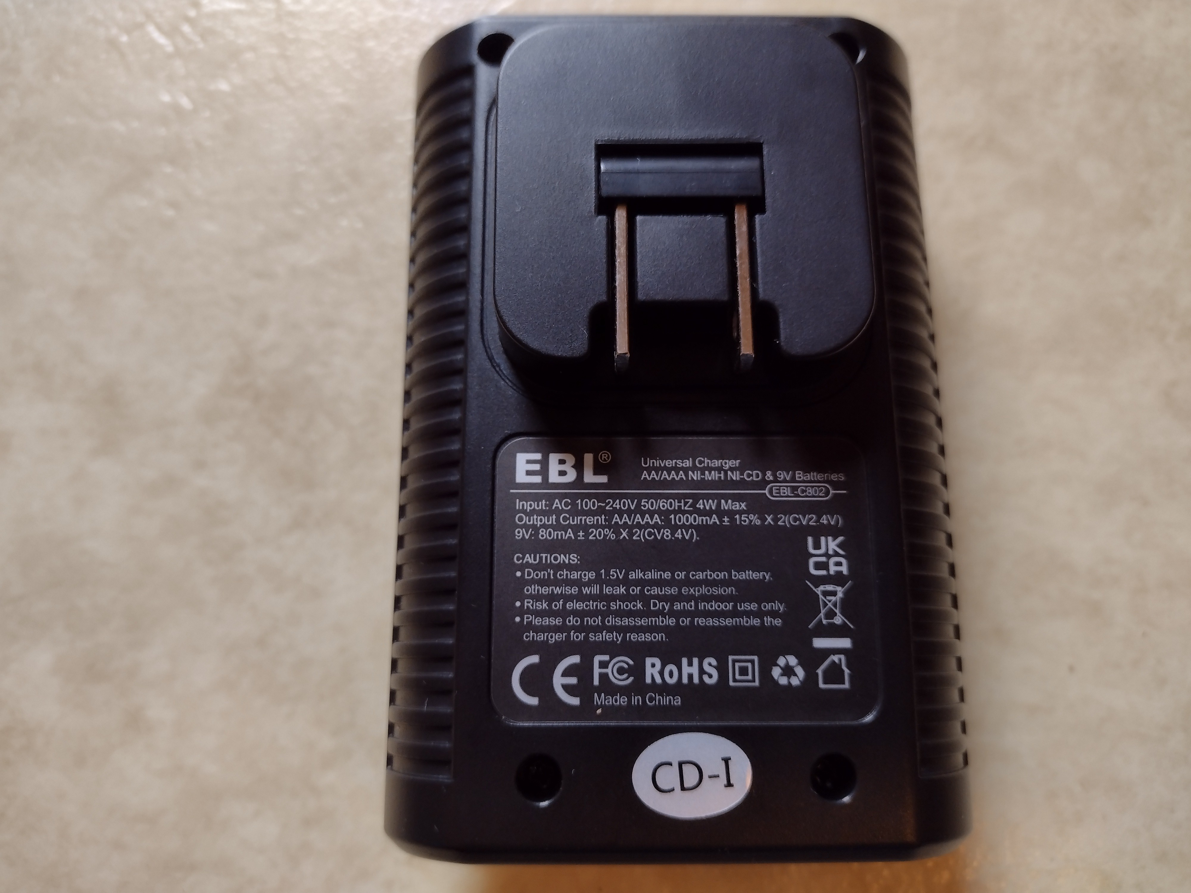
I got bored one day, so I cracked open a battery charger I got. I was curious if it was just a dumb charger when it came to 9v batteries like many chargers out there, or it actually monitored the state of charge. The model of the charger: EBL-C802.
With it opened up:

It quickly became obvious why this charger requires charging AA/AAA cells in pairs. It charges two cells in series. It's likely done this way as a cost reduction measure. Sadly the main chip that controls the charging is missing a label, almost certainly sanded off.
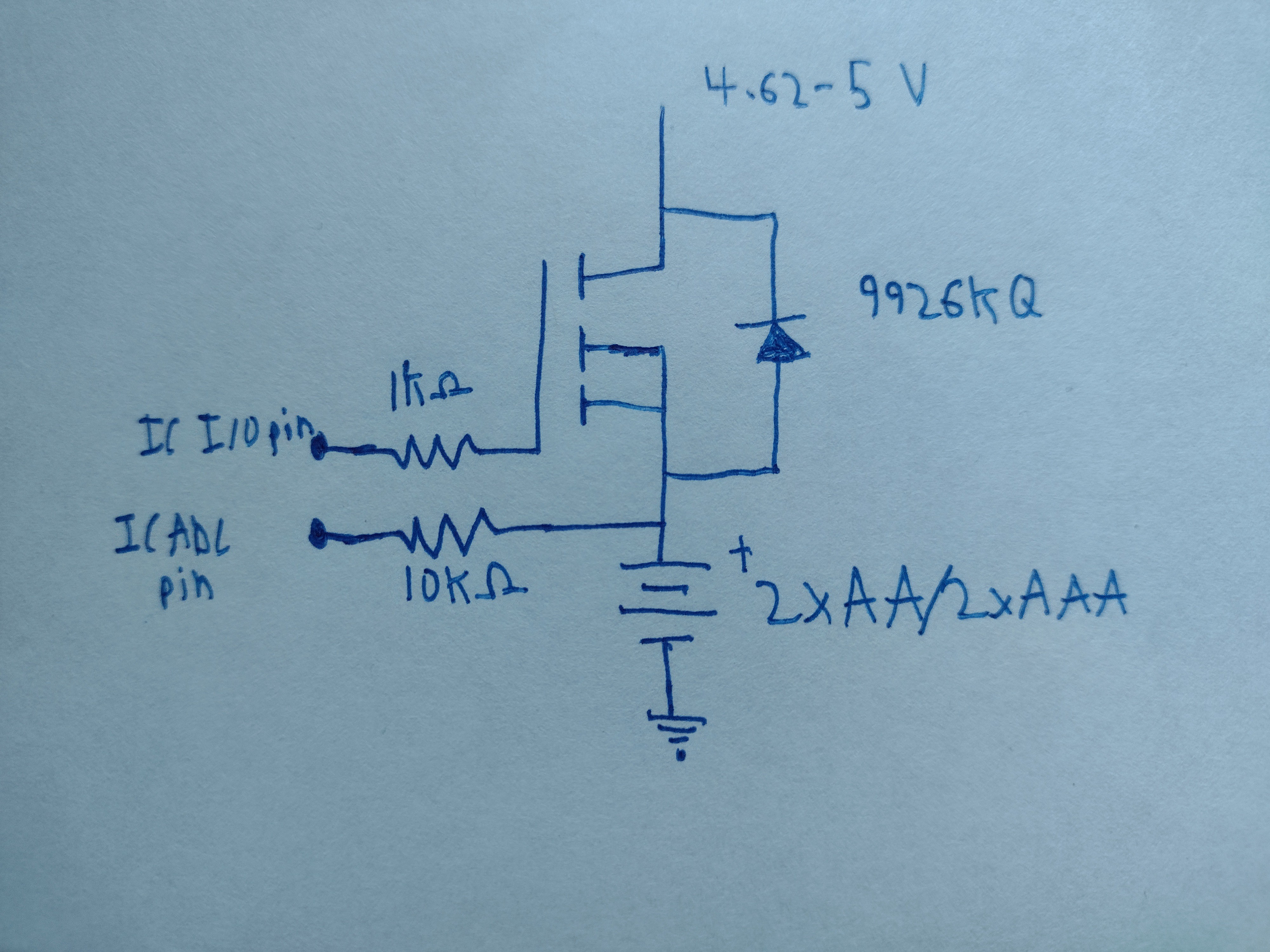
Below is a schematic for the AA/AAA charging circuit. There's two circuits for charging two pairs in total. It's a pretty simple circuit. A mosfet is turned on/off to control charging and voltage of the two cells in series is monitored by the controller chip though a 10K ohm resistor.
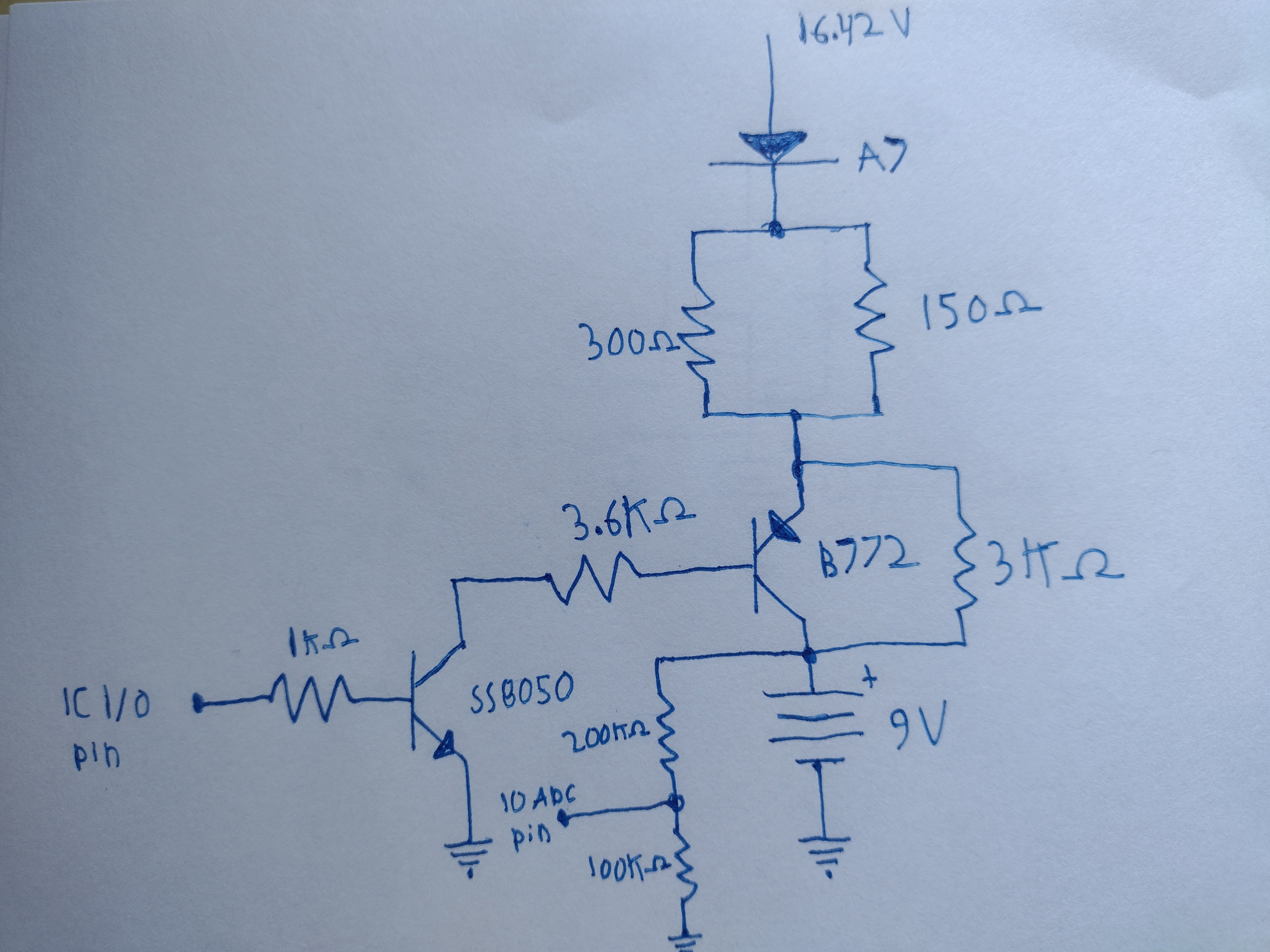
Below is a schematic for the 9V charging circuit. There's two circuits as two 9V batteries can be charged at a time. This circuit is a bit more interesting. It doesn't operate as a dumb charger as the controller chip is apparently monitoring the battery voltage via a resistor divider. The circuit trickle charges the battery even when the B772 transistor is turned off via a 3K ohm resistor.
I have some other observations to note about the charger, but it's close to midnight for me. I'll be sure to update the page later.
Discussions
Become a Hackaday.io Member
Create an account to leave a comment. Already have an account? Log In.