 AMIT KAUSHIK
NOTE: This project is gradually improving. It is fully functional at this point, but it could be better.
It started as a pen plotter based on the entrails of a printer. It uses a pen to draw paths from a vector graphics file(SVG file). I wanted to make it do something that I couldn't do by hand, so I fed it a complicated image, a pcb layout. I then thought "Why can't I replace the pen with a small router and make something truly useful?" So I'm setting out to do just that.
There are numerous DIY pcb mills out there, but their router bits alone cost more than the planned budget of this project. It's not that I can't afford it, I just want to see if this is possible. I'm open to ideas and criticism, so let me know what you think.
- 1×TD62003AP darlington array
- 1×Motor driver circuitry
- 1×stepper motor
- 1×DC motor - 12V
- 1×tact switches
- 1×ATMega 328-P
- 1×PC power supply
- 1×0.8mm drill bit
- 1×various wires, screws, resistors, bits of metal
Some problems and limitations
3 months ago • 4 commentsAlthough this mill has produced some good results, it has also made some garbage. It would be naive of me to expect this mix of dumpster parts to perform as well or reliably as a proper mill. I don't want to make this sound too discouraging, but I'll try to describe some of the weak points of this project.
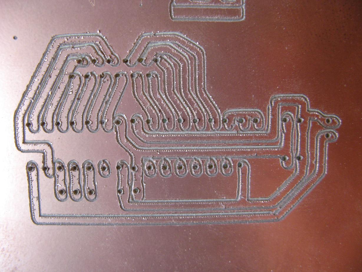
The X and Y axes behave exactly as they did in the printer. One motor moves the print head along a shaft using a toothed belt, while the other turns a roller that moves the object via friction. I have not had any real problems with the print head axis, but the paper axis is not as reliable. There were no problems when I was simply drawing on nice, flat paper. When milling, however, I produce lots of chips, dust and bumps in the surface. Usually these are able to go through the rollers just fine, but sometimes something gets caught and the board slips slightly. Unfortunately, even a slight shift can completely mess up the result. Here is a picture of a pcb for which there was a little slip that caused the drilled holes to be off. As a result, this pcb is no longer functional.
I also had a problem with friction wearing out the plastic "bearing" that guides the bit. It is not actually a bearing, but simply a tight hole in the plastic base of the Z-axis. While milling parts for the stargate project, the mill had to work for rather long periods of time. After a while I noticed that the bit had enlarged the hole in the plastic. It probably melted slightly from friction. I started applying a little oil each time I use it, but the enlarged hole has thrown the precision way off. Of course this could be fixed by replacing the plastic part and remembering to oil it.
A third problem is with cut depth. At this point I have to calibrate the cut depth each time by eye. I've looked at zeroing methods used on other designs, but they would not work here due to slop in the Z-axis. I'm usually able to eyeball a reasonable depth, but sometimes it is just a little too shallow, causing poor electrical isolation, or too deep, causing too much loading on the bit that results in poor precision.
This project has been very educational and a ton of fun. I'm pleased with the way it has turned out, considering the cost and parts used. But with these problems, pcb production has been a long and wasteful process. I'm looking for an alternative and these are some of the options I'm looking at:
- A properly designed and funded mill.
- Chemical etching, which I am trying to avoid.
- Buying them from a fab house. This gives the best result, but lacks fun, education and the feeling of hacking.
- An entirely new experimental method. This is by far the most difficult and educational way. If I can do it, maybe I'll enter it in the hackaday contest.
Do you have any other ideas?
A new use and big software updates
4 months ago • 0 commentsIt is always satisfying to find more uses for projects. I guess that's because so many of them just end up on a shelf collecting dust, not that that will likely happen to this tool.
I am working on a stargate for the sci-fi contest (shameless plug for our entry) and was faced with the task of carving lots of tiny details into thin, flat plastic. What an ideal task for this mill. I drew up some svg images of the stargate details and tried milling them into some 1.2mm polypropylene sheet. Here are some of the results.
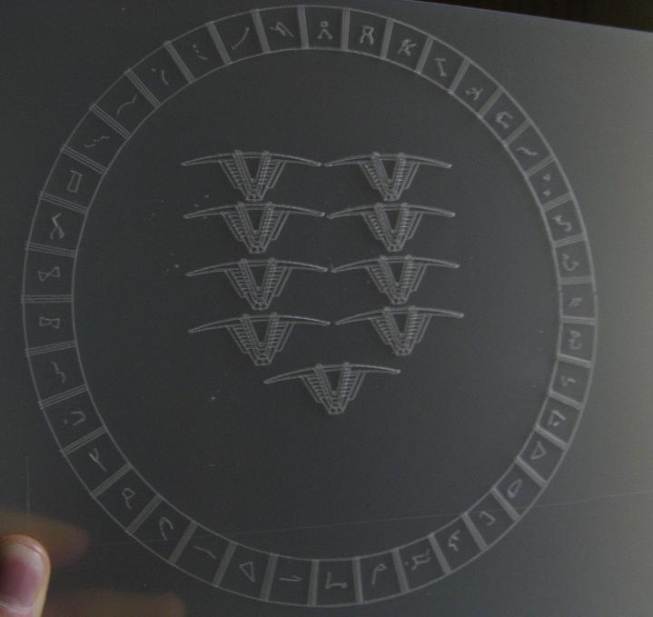

It was a great success. It also led to several significant software changes listed below.
- Cut depth is adjustable on the fly via the processing sketch.
- All important parameters on the controller can be set via processing.
- The math was rewritten to solve some accuracy bugs and be more efficient.
The updated code is in the usual places:
- SVGMill.ino (arduino code)
- SVGReader2.pde (processing code)
Accuracy improvement and drilling capability
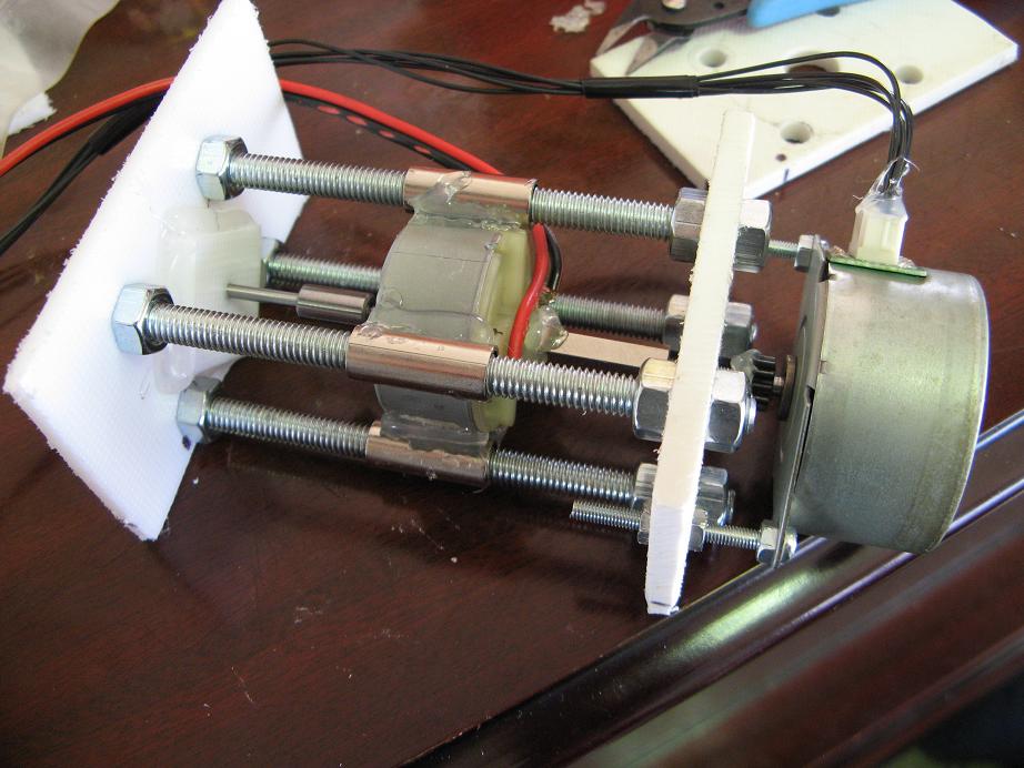
4 months ago • 2 commentsI was not very impressed with the sloppyness, so I decided to redesign the Z-axis to reduce lateral play in the bit. I also thought it would be great if I could drill holes at the same time. I spent another $2 and got some new threded rod and a 0.8mm bit designed for a hand held router(dremel type thing).
The bit now travels through a snug, but not tight, hole in two layers of 5mm HDPE. Yes, that would be the cutting board again. This takes the side loading off of the motor and holds the bit much more steadily.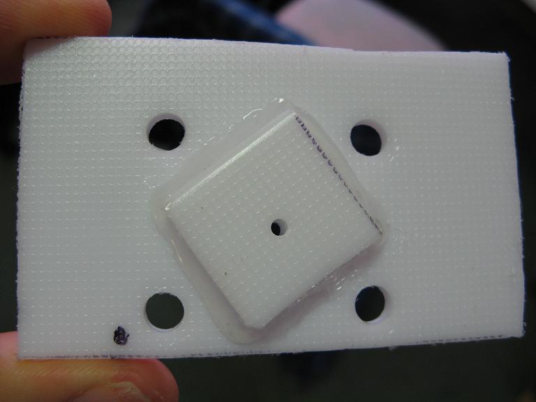

The new bit is much longer and needs more travel for drilling, so I lengthened the z-axis with some new threaded rod. Other than the new bit, new plate with hole for the bit, and new threaded rod, the hardware is pretty much the same.
The software needed some upgrades to handle drilling. Since there is no single point object in the SVG language, I just made tiny line segments with length below some threshold value. The code interprets these tiny segments as drilling locations and sends a drill command to the arduino. The updated code is here:SVGMill.ino - the arduino code
SVGReader2.pde - the processing code
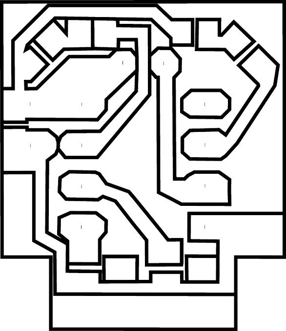
And here is the result. I made the pcb a bit more traditional in style this time. The result is still far from perfect, and there is one trace that is just barely surviving and probably needs a good solder coat, but it is far more precise than the last version. Oh, and it has holes automatically drilled. That's a huge improvement. First is the ideal image, then the actual result.

Discussions
Become a Hackaday.io Member
Create an account to leave a comment. Already have an account? Log In.