 Ken Yap
Among the old projects in my junk box was a digital clock I made in the late 70s, using the National Semiconductor MM5371, a one chip clock.
Back in the day I used an iron core transformer to supply power. I decided to replace this with a wall wart supply supplying 15V AC that used to power a modem, so that I wouldn't have to worry about exposed mains wires. This required some rework of the rectifier circuit. (I can't power it from DC, I still need the mains frequency reference.)
I fixed up the inevitable breaks and dry joints. Fortunately none of the electronics had failed, only my lousy soldering of the time.
When I powered it on, all the segments lit up., some more than others Although a semi-blinking PM LED indicating power fail seemed to indicate that the clock chip was intact. This puzzled me greatly and I set the project aside for a few months.
Eventually I looked at the circuit again. The MM5371 is interesting in that it can drive multiplexed 7-segment plasma displays directly. Even though it's implemented in PMOS technology, it holds off fairly high voltages, up to 45V, see this datasheet extract.
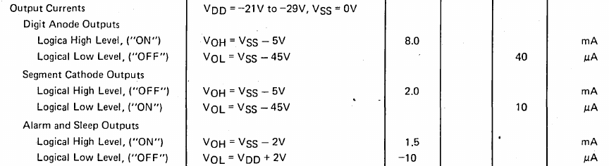
This is sufficient margin between the firing and sustaining voltage of plasma displays to turn them off. The voltage level translation is done by capacitors, you'd have to look at the reference circuit to work it out. Trust me. 😊
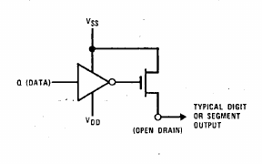
Here is the internal drive transistor:
Two observations emerge from these specs:
- The digit anode outputs go towards Vss (positive) to turn on. This makes sense as the digit drive is connected to the anodes. However the segment cathode outputs go towards Vss (positive) to turn off. Again this makes sense as the cathode voltage must be drawn closer to the anode to extinguish the glow.
- The logic level of high is not quite Vss, and is a minimum of Vss - 5V. This had implications for the circuit I designed decades ago.
To drive cathodes of the LEDs I had NPN transistors driven from the digit outputs, sinking current. To drive the anodes of the LEDs I had PNP transistors being turned off by the segment outputs, sourcing current. In other words a common cathode display.
All well and good, but I had neglected the 6th line of that datasheet extract. The open drain has a fairly high on voltage, up to 5V. This is not enough to turn off the PNP transistor; less than 0.6V is required.
Why hadn't I encountered the problem decades ago? I remembered that I had two positive voltage rails, a fairly high 18V rail to supply the MM5371 and a lower 9V rail for the LEDs. In that circuit, the PNP transistor is biased negative when turned off. With a single rail in my new configuration, I didn't have this offset.
Quick fix: I inserted a zener diode in the LED supply so that the PNP transistors could properly turn off.
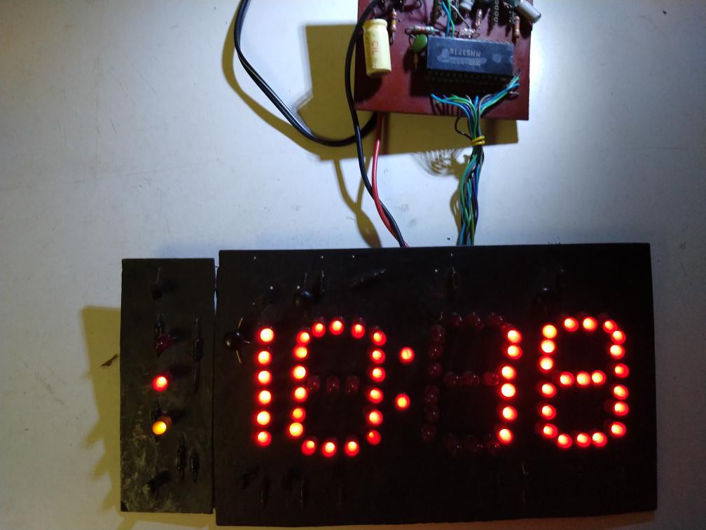
You'll notice some other circuitry on the small PCB. Those are alarm and PWM brightness control options using 555s which I never implemented. The driver transistors are on the display board. I sprayed painted the board black to have maximum contrast. The digits are 5 cm high. Now I have to find a casing for it, something I never go around to doing. Presentation isn't my strong suit. 😊
Other for the facts that the MM5371 is out of production (any you find these days on eBay are old stock for replacements and command high prices), and that the PMOS technology requires higher voltages of 21-29V, it's still a compact 1 chip solution. Pretty good for a chip that came out in 1977. I still have a few MM5371s. I might consider making more large display clocks, this time with super bright LEDs. Or sell the chips on eBay and retire. 😊
Update
I prefer the look of wood to plastic so I'm not keen on using 3D printing plastic project boxes. A search showed that 3D printing of wood has been developed. But this got me thinking, why not cardboard for project boxes? A lot of projects are not portable so the box doesn't need much strength. Electronics is light these days. You could decorate the box however you like, There would new skills to learn, including designing folding patterns on a computer.
I had a DIY dinner kit box lying around so I decided to test this idea. I cut a port for the display, stick the board inside, and voilà:
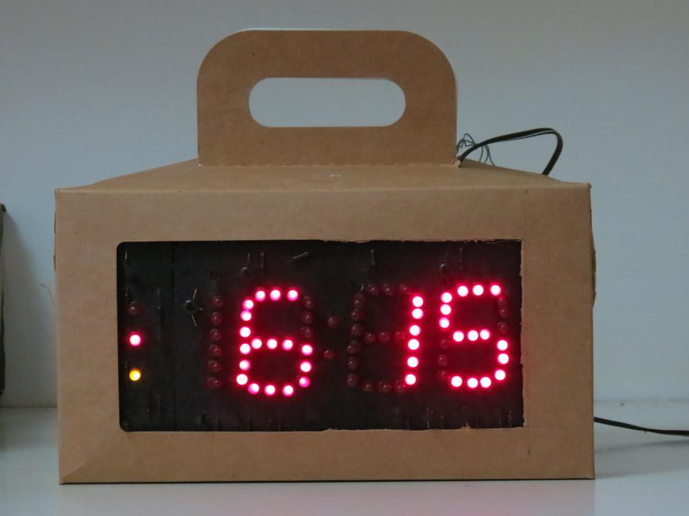
I may be onto something. 😊
Discussions
Become a Hackaday.io Member
Create an account to leave a comment. Already have an account? Log In.