 Patrick
I added the AudioControlSGTL5000 object to my port of the Teensy Audio Library available at
https://bitbucket.org/phorton1/src-circle/src/master/
This is, of course, just part of my ongoing
rPi bare metal vGuitar Rig
project, but I felt like a “page” would be the best way to present this information.
These classes allows one to connect a Teensy Audio Shield, or other SGTL5000 to a Raspberry Pi within the bare metal Circle environment.
It turned out to be a little more difficult than I originally thought it would be.
The sgtl5000 / teensy shield absolutly requires an input MCLK.
For 44.1khz sound, that clock has to run at 11.289Mhz. Here’s a handy snippet of code to produce an
11.289 Mhz clock in Circle:
LOG("starting MCLK",0);
u32 freq = SAMPLE_RATE * 256;           // 11289600
u32 divi = CLOCK_RATE / freq;            // 44
u32 modi = CLOCK_RATE % freq;           // 3257600
u32 divf = (modi*4096 + freq/2) / freq; // 1182
    // printf("divf=%d should equal 1182\n",divf);
    // the above math overflows 32 bits
divf = 1182;
m_MCLK.Start(divi, divf, 1);
There is no good way on the Pi to generate 3 synchronized clocks, the other two being needed are the the BCLK (bit clock) and FCLK (frame clock, also known as the LRCLK). The bcm2835 PCM peripheral can, as a special case, generate a synchronized FCLK for a given BCLK, so it can usually act as a master to i2s devices, but for the sgtl5000, which requires a 256fs master clock, it just cannot reasonably be programmed to act as an i2s master.
So, instead, my code for the rpi generates the 11.289Mhz MCLK on GPIO4, sends it to the sgtl5000 (teensy audio shield), which then acts as the i2s master, generating the BCLK and FCLK signals based on that. And therefore, in Circle, the AudioControlSGTL5000 is actually not implemented, and you must use the AudioControlSGTL500slave device instead.
It works ok, however, and so is worth checking in.
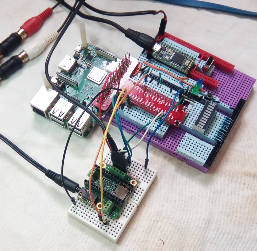
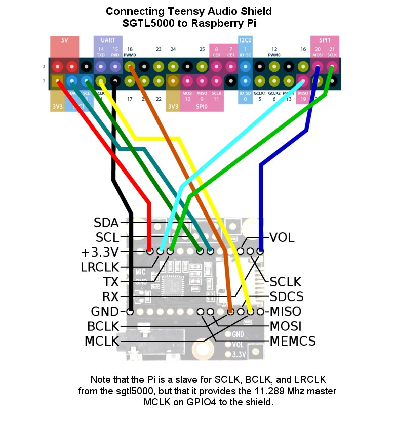
Below is a diagram showing the pin connections between the Raspberry Pi and the Teensy Audio
Shield. Note that this is *just* the Teensy Audio Shield … there is no Teensy
running the codec … it is connected directly to the Pi.
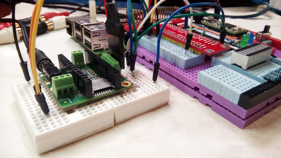
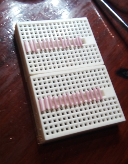
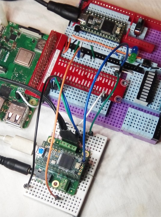
I made a simple breadboard for the Teensy Audio shield by gluing two of the small standard
breadboards together (after sanding the joining edges to remove some space), and running jumpers.
This allows me to just use regular wires to connect things. I HATE DUPONT FEMALE CONNECTORS !!!
Circle TeensyQuad device
I also added two additional new classes, AudioInputTeensyQuad and
AudioOutputTeensyQuad to the library. These allow the Pi
to be connected to a Teensy that is actually running an existing Teensy Audio Library
program, so the Pi can act as a (relatively larger, big
brother) audio co-processor
to the Teensy.
The teensy MPU has two i2s modules (as opposed to the one on the bm2835) that run synchronously. Paul has created the AudioI2SQuad input and output devices to allow two teensy sound shields to be stacked for quad io.
These classes allow you to easily use any rPi, including the zero and 3B+, as a DSP co-processor to a teensy audio application. It *may* even allow you to retrofit such an additional processor into your existing Teensy audio application with a minimal set of changes.
 +-------------------+      teensy       +--------------------+
 |   Teensy Audio    |   quad channels   |       rPi          |
 |    application    |      2 & 3        | acting as an audio |
 |    using quad     | <===============> |    co-processor    |
 |    audio device   |                   |                    |
 +-------------------+                   +--------------------+
      ^        |
      |        |      teensy quad
      |        v     channels 0 & 1
     IN       OUT
The teensy quad device channels 0 and 1 are used for the main audio input and output, from a mic or line input, out to line or the headphones. The teensy quad device channels 2 and 3 are used to communicate with the rPi.
From the rpi's perspective, the teensy is simply another i2s IO device (that happens to
use a 16 bit channel width instead of 32 bits, as that is the channel frame packing that
I see with the default build of the teensy quad libraries in the Arduino IDE).
There is no corresponding "control" object for the streams … it is presumed that
control functions will be handled by the native teensy application.
The test program consists simply of a stereo pass through. The sound comes IN to the teensy shield on quad channels 0 and 1. It is then sent to the rPi on OUT channels 2 and 3, where it is “processed”. The Pi then sends it back to the teensy on quad IN channels 2 and 3, and the teensy simply sends the input from those to the main 0 and 1 OUT channels to headphones or the line out.
Here are the pin connections. Note that we don’t need (disconnected) the MCLK wire from the previous section.
     rPi   gpio   Teensy 3.2_quad  3.6_quad   normal_teensy_i2s

    BCLK    18   <----  9          9            9
    FCLK    19   <----  23         23           23
    RXD     22   ---->  15 tx1     15 tx1       22 tx0
    TXD     21   <----  30 rx1     38 rx1       13 rx0
Here is the INO sketch running on the teensy using the native Teensy Audio Library:
#define WITH_SERIAL  0

#include <Audio.h>

#if WITH_SERIAL
    #include "myDebug.h"
#endif


AudioControlSGTL5000    control;
AudioInputI2SQuad       input;
AudioOutputI2SQuad      output;
AudioConnection         c0(input, 0, output, 2);
AudioConnection         c1(input, 1, output, 3);
AudioConnection         c2(input, 2, output, 0);
AudioConnection         c3(input, 3, output, 1);


void setup()
{
    #if WITH_SERIAL
        Serial.begin(115200);
        display(0,"teensyPiQuadTest,ino started ...",0);
    #endif

    AudioMemory(12);
    control.enable();
    control.inputSelect(AUDIO_INPUT_LINEIN);
    control.volume(0.7);
    control.lineInLevel(0,7);

    #if WITH_SERIAL
        display(0,"teensyPiQuadTest.ino running ...",0);
    #endif
}


void loop()
{
    #if WITH_SERIAL
        static elapsedMillis timer = 0;
        static int counter = 0;
        if (timer > 3000)
        {
            display(0,"counter(%d)",counter++);
            timer = 0;
        }
    #endif
}
And here is the Circle program in bare metal running the ported Teensy Audio Library:
#include <audio\Audio.h>

AudioInputTeensyQuad   input;
AudioOutputTeensyQuad  output;

AudioConnection  c0(input, 0, output, 0);
AudioConnection  c1(input, 0, output, 1);


void setup()
{
    printf("02-StereoPassThru::setup()\n");
    AudioMemory(80);
    printf("02-StereoPassThru::setup() finished\n");
}


void loop()
{
}
There are a couple of things to note about the Audio Shield hardware in this configuration
(1) you must remove a small capacitor that is connected to pin 15 on the audio shield. It’s ok. Paul added this capacitor to tame signal noise when pin 15 is used with a volume pot, but it’s not really needed. The teensy native quad device sends out the i2s on pin 15 and it definitely doesn’t work if that capacitor is in place. You will need to use a different pin besides for the volume control to use the native Teensy Quad Device.
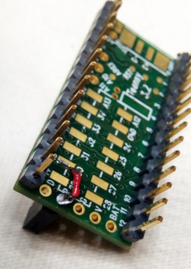
(2) On the teensy 3.2, the second i2s channel RX1 pin is gpio30.
This pin is on the bottom of the teensy 3.2, and so I had to add a jumper and wire to my teensy
3.2 for this test configuration. The alternative is to use a teensy3.6, which brings the
second i2s channel RX1 out to gpio38, which is a “normal” pin on the teensy 3.6. All my
teensy 3.6’s are occupied at the moment, and It only took a few minutes to solder the
jumper on one of my 3.2’s, so the proof of concept is with a teensy 3.2. I
scratched away the connection between the Teensy "program" button and one of the holes on
the edge so that I would have someplace to solder a female connector:

Running it on a Pi zero
It’s been a while. I’ve been using the 3B+ for the last couple of months,
but just to prove it works, I broke out an old Pi Zero, and did a clean build of Circle
and the test program and kernel with RASPPI=1.
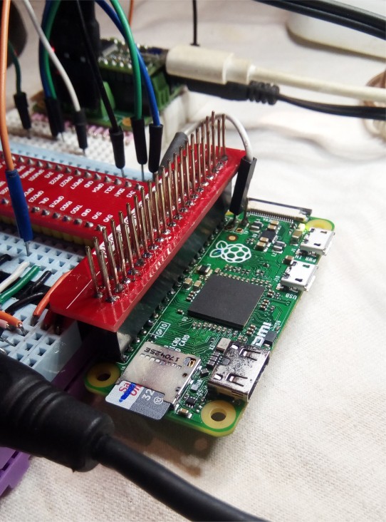
My breakout breadboard makes it easy to swap a different Pi into the circuit without disconnecting any wires. It took about 10 minutes to verify that the same program worked on the Pi Zero as had just worked on the rPi 3B+. That's one nice thing about the Circle environment. It only takes about 5 mintues to do a clean build, as opposed to what, several hours for a Linux build? So it was not hard to recompile everything for the zero.
I plugged it in and it worked the first time !!
Gotta Love It!
- Patrick
Discussions
Become a Hackaday.io Member
Create an account to leave a comment. Already have an account? Log In.