 Patrick
-
Getting back into it ... (IT WOULD BE NICE IF HACKADAY HAD AN API TO CREATE PAGES AND PROJECTS)
12/30/2022 at 14:43 • 0 commentsHey there,
It's been a while since I posted anything to hackaday.Over three years, in fact, since October, 2019.
I still haven't found a good pipeline to allow me to create projects on github, and then denormalize the content to hackaday, youtube, and thingiverse.
It is very time consuming to put it all on github, then produce youtube videos and thingiverse pages for each project, and then use hackaday for the final presentation.
Nonetheless I have continued doing projects continuously since my last post. Some of those projects have been well documented on github, and even on youtube, but even there I have fallen far behind, only taking a very limited set of projects that I completed public, while some very interesting projects, due to dependencies on some private source code, and/or pure laziness, have not been publicly revealed or documented.
I am going to try to remedy that by focusing on documentation, and avoiding new projects for a while.
That means that you will (hopefully) be seeing some projects presented here that took place a while ago, and the date-time stamps on the projects, and pages here on hackaday will not be representative of when the projects actually took place.
My goal is to try to get caught up a bit, so that I meet the basic goals of presenting open source projects on github and thingiverse and using hackaday and youtube to nicely present them in a more entertaining manner.
So, please bear with me as I work through the process. I will be thinking about a good way to maintain all of this documentation.If anyone has a good way to automatically generate hackaday pages and projects, something I could run against my github readme files which would generate the basic info on hackaday, that would be handy.
Same for thingiverse ... I'd like to present my 3D printing and laser cut stuff there, but have it driven from readme (MD) files I create and put on github.
*** IT WOULD BE NICE IF HACKADAY HAD AN API TO CREATE PAGES AND PROJECTS***
LOL, that might become a project of it's own :-)
Thanks,
- Patrick
-
Help matching impedances
10/15/2019 at 22:51 • 3 commentsHey there!
I'm looking for some help in understanding impedance matching. I'm hoping one or more of you technically savvy electronics folks will jump in and give me a simple circuit recommendation.
Specifically I want to try to build a passive "pad" that goes between the output of a Fishman Prefix Plus built-in guitar pre-amp and the input of an IRig HD2 guitar-audio-to-usb converter. My issue is that, as it stands, I have to turn the volume control of the pre-amp as close as I can to it's minimum value (like 0.01, which is iffy), and set the gain of the Irig input hard to it's minimum value to get any kind of decent sound. Anything else results in lots of distortion. I'm trying to get a clean guitar sound.
https://www.fishman.com/products/series/prefix/prefix-plus-t-onboard-preamp/
https://www.ikmultimedia.com/products/irighd2/index.php?p=specs
I get the feeling that by using the extreme lowest setting on the pre-amp I am not in the sweet spot of the pre-amp design. I feel like it makes the sound tinny ... I'm always lacking bass when I use the device (compared to just plugging my guitar into the Yamaha Stagepas PA). It's just my noob idea that the amp was probably designed to be used in the middle, rather than at the extremes of its gain settings.
So, I'm thinking about making a passive "pad" that basically consists of two resistors.
input    O------- R2 --------+----------------O output
                             |
                             R1
                             |
ground  O------------------- +----------------O ground
My basic, very limited, understanding is that such a passive pad consists of a voltage divider created by resistors R1 and R2. I really have no idea what values to use, although I sort of think their ratios should be about 9:1 where the value of R2 is about 9 times greater than the value of the "shunt" resistor "R1". Rather than just guess, I thought I would ask the community.
The specs for the devices are copied from the user manuals Here is what I see:
FISHMAN Guitar Pre-amp
- Nominal Input Level: -20dBV
- Input Impedances: 20MOhm
- Output Impedance: "Less than 3.5kOhm"
- Nominal Output Level: -12dbV
IRIG HD2 audio-to-usb converter
- Maximum Level: from 307mvpp to 8.36Vpp
- Gain Control Range: 28.7 dB
- Input Impedance (guess): 380 kOhms
I cannot find the actual input impedance specification for the IRIG HD2. There is a reference in the user manual that it is a "high-Z input". I am guessing it is simllar to the input impedance for the IRIG2 which IS specified as 380kOhms.
----------------------------------------------------------------------------------------------------------------------------------
So, given those specs, what should be the values of R1 and R2?
Any other thoughts on what I'm trying to do here? I'd sure like to get a good sound and a feeling of control instead of a tinny sound and a pre-amp that is turned down to 0.01 ....
Thanks in advance for any replies.
- Patrick
-
Why doesn't someone make a WS2812b Switch Array?
09/07/2019 at 06:17 • 9 comments![]()
Two things:
- I can’t believe this worked (almost the very first time) !
- I’m surprised nobody else seems to have done this before !
OK. I have been looking for months on the net for somebody, anybody, who has combined WS2812b addressable LED’s with switches to create a switch array. At the end of this I explain why I would want such a thing, but for now just please understand that I could not find any other examples of anyone selling, or even trying, something, like this.
Perhaps no-one needs it, or perhaps it exists, but is just not on the web, but perhaps no one has thought of it before. In any case, it seemed to me that it would be fairly straightforward to combine a switch with each ws2812 in an array (or a strip), and be able to tell which button is pressed, if any, based on the timing of the signals being sent to the LED’s.
Now please understand that this is very crude hardware and code. I didn’t even expect it to work. The LEDs are supposed to have capacitors from power to ground, most schematics recommend a resistor from the output pin of the Teensy to the input pin of the LED, and I’m pretty sure that no electrical engineer out there would recommend hooking the DIN (data in) pin of each LED through only a switch directly to a bus line to an input pin on the Teensy. Something has to fail, right? Oh, and always use a separate power supply for the ws2812’s lol 😊
So, please let me say that I will appreciate any comments, or contributors, that can design a proper circuit, help me to understand how it should work, and/or really want to dig in to write good code for this purpose.
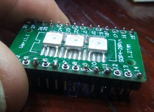
CIRCUIT BOARD
I have a couple of ws2812 arrays sitting around (an 8x32 and a 4x4), but I don’t have any strips. That’s a shame because the strips look like you can easily cut one off and work with it. You probably have a strip you can just cut up! I don’t want to cut up the arrays, but I do happen to have a bunch bare ws2812 LEDs that I bought experiment with. So I rummaged through my stuff and found a little circuit board I could solder them to. That being about my third try to air-solder SMD’s, I glued them on with superglue, a little too much in one place, and then glommed some paste solder on em with a toothpick, and blew hot air on em. Even though it was only 215C, I basically tortured the LEDs as I had to burn through the superglue on one of the contacts. Nonetheless, they conduct electricity, and there are no shorts.
![]()
I added some pins to the board, so then I had three ws2812’s I could play with on a breadboard. If you want to build one of these, you probably can just cut one off a strip and use alligator clips or whatever it takes to hook them up.
The first circuit I made used jumper wires. Much to my surprise I hooked up the 5V and ground and got the Teensy example basic ws2812 test program working with my little 1x3 array of LEDS in a few minutes,.
So then I decided to try to write some code to make it work as a switch array.
THEORY OF OPERATION
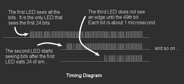
As you send serial data to the LEDS (actually, to the first LED’s DIN – data in - pin) using the ws2812 protocol, each LED takes 24 bits to display an RGB value. OK, actually it’s GRB, but that’s not important!
After the first LED “eats” the first 24 bits, it starts passing the remaining bits onto the next LED. So the second LED does not see any bits (rising edges) until the first LED is done with those first 24 bits. Then the second LED “eats” the second 24 bits before it starts passing the remaining bits to the third LED, and so on.
![]()
The other thing worth knowing is that each bit in the ws2812 protocol, both ones and zeros, has a HIGH and a LOW part. ...
Read more »
This user joined on 05/21/2019.
 Thomas
 Lutetium
 Wesley Archer
 Connor Yamada
 conradcn
 Hsin-Tien, Chu
 Rebecca Buckingham
 Julien Provenzano