 helge
helgeWhy I don't like USB in the lab
When lab setups don't fall into disuse and get scrapped, they are usually passed down through generations of PhD students - and there doesn't always seem to be an incentive to spend time to improve a working setup.
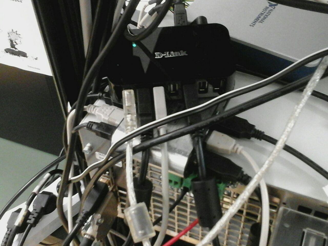
... and then one ends up with such organically grown USB cancer:
While USBTMC (USB Test and Measruement Class, [1]) allows ease of use of a subset of lab equipment, one is usually at the mercy of manufacturers to support newer platforms and control software implementations to properly handle USB devices.
Practically such equipment communication ends up being vulnerable to faults by re-enumeration and broken handles to once-functional virtual COM ports.
Let's change the requirements too and ask to allow multiple control PCs and setups sharing measurement equipment - and USB stops making so much sense altogether.
To spice things up, I'm adding transients of 1 .. 20 kA/µs and 10-50 kV/µs into the mix. Under these conditions, and with setups not enclosed in metal test cells, with filters added to all cables crossing the shielding walls, USB struggles through common mode (CM) noise and yet-to-be-identified perturbations.
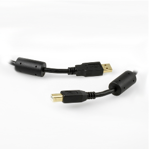
On a side note: the only cables we've found to make a difference are "CU-HQ-20". They have honest copper cross-sections, proper shielding braid and ferrite filters on both ends. Expect to play 15€/pc.
Ethernet and PoE in the lab?
Ethernet enables multiple pieces of equipment, actuators, sensors, control interfaces and PCs to be connected, both locally and remote, and satisfies the requirements for maximum flexibility with cheap and ubiquitous components.
Thus we should be looking at the 10BASE-T and 100BASE-TX physical layers in terms of noise immunity and voltage handling capabilites and see how PoE fits into the picture.
Magnetics!
Ethernet has become very popular in industrial applications [2]. As far as noise immunity is concerned, common-mode filters are often part of integrated-magnetics RJ45 connectors (commonly called "MagJack", which happens to be a name trademarked by BEL). Having the filter magnetics right behind the connector pins in a shielded can connected to the enclosure and bypass capacitors right next to the connectors is the a best effort approach to mitigating conducted and radiated emissions into a network enabled device. The PoE lines are commonly outfitted with ferrite beads to block common-mode transients coupling into the DCDC converter circuitry.
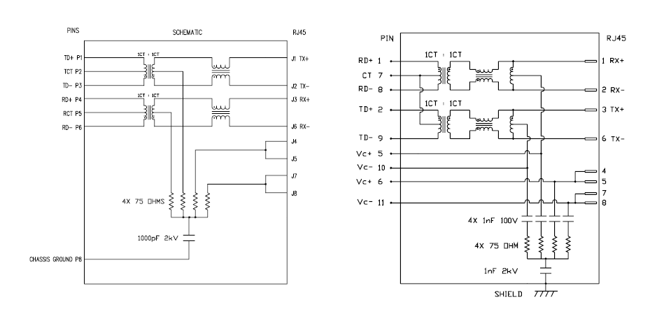
Below two types of MagJack circuits are shown [3]. The right one is outfitted with separate PoE pins which hook up to full bridge rectifiers and an isolation converter that also handles the PoE communication. Power is transmitted courtesy of a common-mode potential difference between differential pairs.
It is to be expected that the patch cable shield is connected to ground of the switch chassis. We have found our first issue: high frequency CM voltage components drop across the CM filter and to a lesser degree across the signal transformer. Additionally, low frequency and DC components are blocked by the signal transformer alone.
Are they really being blocked?
Let's look at the signal transformer:
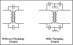
These parts tend to be produced as a multifilar toroidal winding, e.g. on a small NiZn ferrite core. The windings have maximized overlap to optimize coupling and to marginalize stray inductance, but then again this also enhances capacitive coupling. This inter-winding capacitance is a low-impedance path for high frequency common-mode noise.
Faraday shields eliminate inter-winding capacitance. For transformers this requires the addition of one or mulitple shielding foils or wire windings in between primary and secondary sides, along with added insulation. I haven't seen them used in ethernet magnetics though.
What would be the best effort? Lacking a teardown survey of PoE switches marketed for industrial applications (please contact me if you happen to have a box of interesting stuff we might take apart and write about what's in there) I can point out only a few aspects:
- some application notes recommend using separate ethernet magnetics and putting two identical parts back-to-back. This can compensate asymmetries in the windings and creates a multi-stage CM filter
- Signal couplers for HomePlugAV (up to 30 MHz) and possibly some other varieties of signal coupling transformers available as off-the-shelf products optimize towards minimizing capacitive coupling and withstand voltage and might be compatible with 10Base-T or even 100Base-TX requirements, as long as one can manage a net 1:1 ratio and sufficient bandwidth.
What's the worst that can happen?
InCompliance Mag shows this nice image [6] of overvoltage damage:
While this may not be pretty, no other transient voltage absorbers (TVS diode arrays?) are present in the standard implementation. Still I'm pretty confident that other devices connected with their own magnetics stand a fair chance of survival even though the switch let go of its magic smoke.
Conclusion? In terms of filtering and ESD protection, industrial switches with enhanced ruggedness may be worth looking into, but one should always crack open the lid and see what's really in there before relying on it.
Speaking of which...
PoE Switches
returning to what was in the mail today and how I intend to give USB the boot in the not-so-distant future: ethernet seems to be the way to go. Lab equipment connected via ethernet and controlled over TCP/IP is shared in the same way as additional I/O interfaces, sensors, and custom hardware.
A LinkSys / SRW224P was procured for 19€ plus shipping, providing 24 ports with 10/100 ethernet and PoE. Nothing special, but just cheap enough to not be upset about when the smoke escapes.
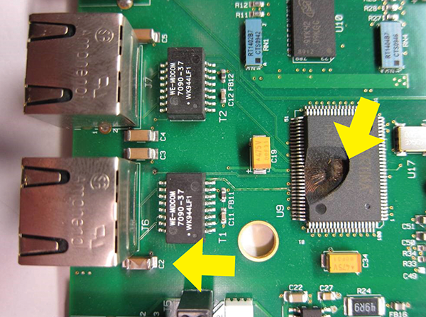
The mainboard is a bit on the large side, and it's nice to see separated quad magnetics and multi-port PHY chips that ensure the connector blocks of eight ports each are properly separated from each other.

The PoE extension is stacked on top of the board, having a separate power cable.
From the network side, there's an array of filtering and clamping devices (GS1G diodes and possibly Zener diodes, polyfuses, bypass capacitors and no ferrite beads. Maybe there are some on the bottom of the main PCB?
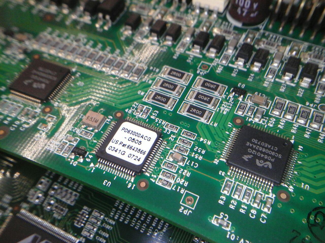
All clearances are rather underwhelming though, definitely nothing I would trust to provide any protection:

12-channel power delivery controller: PD64012 https://www.microsemi.com/sites/default/files/datasheets/nda/06-0003-058%20DS-PD64012G%20ver%203.1.pdf
PoE magnetics: Mag-Tek H48502MN http://www.mag-tek.com.tw/downloadbox/100quad/H485XXMN.pdf
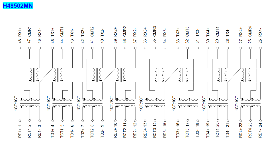 the diagonal lines look wrong as there shouldn't be a connection between TX and RX paths. Possibly just a datasheet artifact.
What's next?
Well, chances are I'll be hooking up power supplies, multimeters, signal generators and some Ethernet UART converters and homebrew reinforced isolation auxilliary power supplies, along with controller and sensor interfaces, and figuring out how to get reliable performance out of ethernet interfaces connected to wide bandgap semiconductor power electronics.
I'll let you know how that switch will survive in the lab.
------------------
[1] https://www.usb.org/document-library/test-measurement-class-specification
[2] https://www.electronicdesign.com/communications/ethernet-dominates-industrial-environments
[4] https://www.tkd-kabel.de/datenblaetter/03/03.15.02.02.pdf
[5] https://www.maximintegrated.com/en/app-notes/index.mvp/id/716
Electrical insulation rating
From a cable datasheet, a pile of standards rains down on us: EN 50173, ISO/IEC 11801, TIA/EIA 568, TSB36, EN50288, IEC 61156-5, PoE: IEEE 802.3af. [4] I'll leave the names here for completeness as it usually takes time to read through these and access to the texts in the first place. Somewhere in there should also be a voltage rating for the cable insulation.
http://www.smar.com/en/technical-article/tips-on-shielding-and-grounding-in-industrial-automation
USB isolation:
If sticking USB devices to a dedicated SoC or PC, you might like the LTM2884 instead (Full speed USB and isolated power module).
Discussions
Become a Hackaday.io Member
Create an account to leave a comment. Already have an account? Log In.