 Christoph Tack
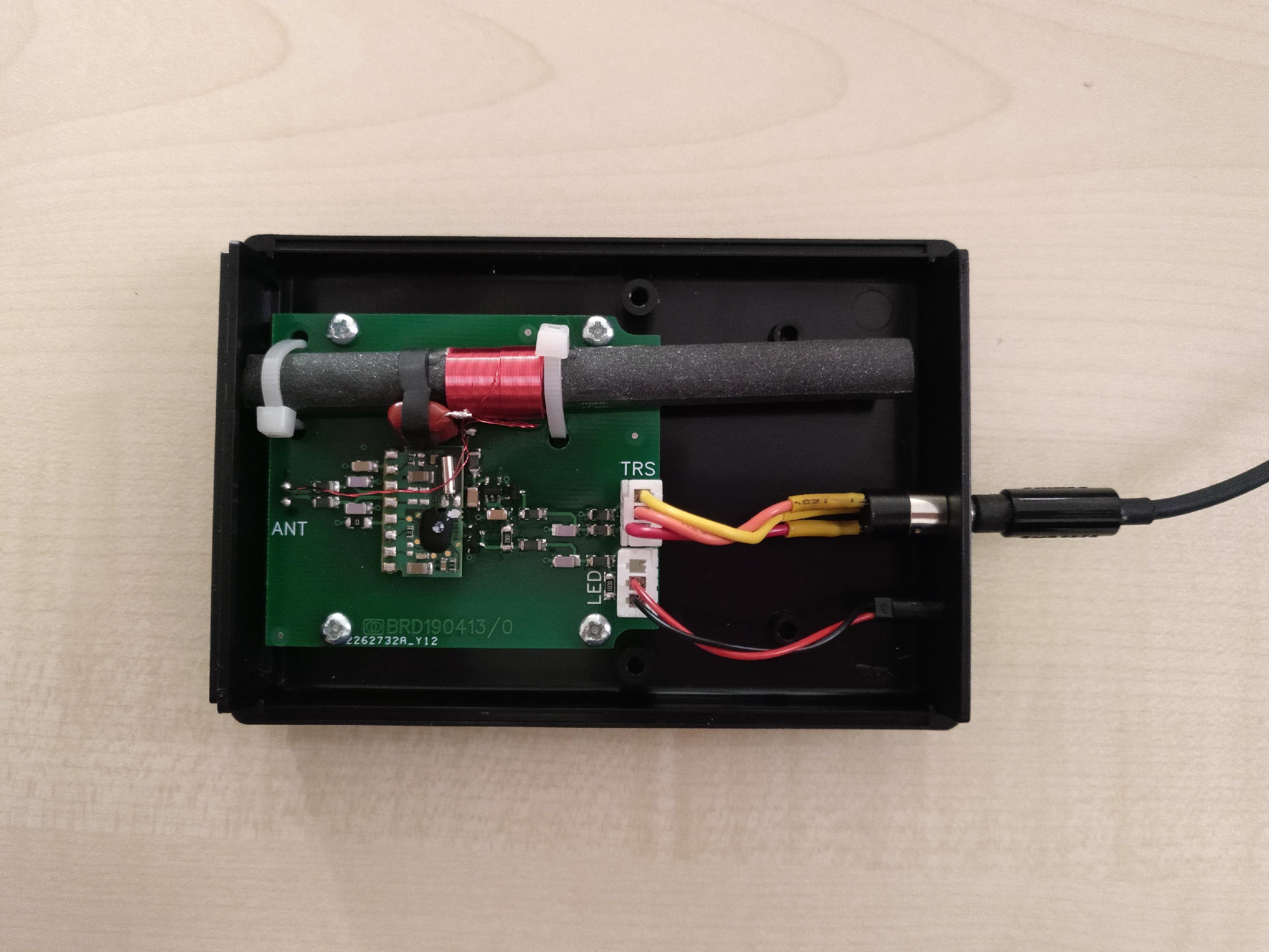
Design
Schematic design and PCB layout can be found on EasyEDA.
Housing
The DCF antenna doesn't work well when it's in proximity to EM-noise sources. Possible noise source are the rest of the electronics of the clock or a laptop. The solution is to put the DCF-antenna and the decoder in a separate housing. It might not be necessary to use the separate housing once the clock is properly designed instead of using the breadboard and flying wires.
Steps to follow:
- Using the Hammond 1593NBK.
- Converting the DWG file to DXF using CloudConvert.
- Cleaning up DXF using LibreCAD
- importing in EasyEDA.
Main components
- DCF antenna : HKW AFET 77.5 - 10x100/70
- DCF decoder : HKW EM6 DCF 3V
- Output drive capability is only 30µA!
Connector
It should be easy for the customer to find a suitable cable assembly to connect the box. The connector should also be small and low profile.
- Stereo audio jack cable :
- flexible, cheap, readily available
- user might be tempted to connect headphones. This must be avoided. At the least, the headphones shouldn't be damaged.
Modular jack cables:- 4pins, 6pins, 8pins, common use in POTS telephony and ethernet.
- Ethernet cables are not that flexible.
- Big connector. Might not fit inside the housing
The initial idea was to mount a TRRS audio headset socket directly on the PCB, Doing this would make it hard to correctly drill the needed hole in the front panel. Moreover, such a connector, which needs to be placed against the wall of the housing would require a longer PCB than stated in the datasheet of the box.
Two JST XH connectors will be used instead. One connects to a panel mount TRRS audio headset socket. The other connects to a panel mount LED.
Cable assembly
Many audio cables are constructed as two pairs of two wires. So the left and right channel each have their ground wire in close proximity. The ground wire is connected to the sleeve. To take advantage of that cable configuration, the GND signal is here also connected to the sleeve.
| JST XH | Signal | Audio jack |
|---|---|---|
| 2 | 3V3 | Tip |
| 1 | OUT | Ring |
| 3 | GND | Sleeve |
Time sync
Five options for setting time have been considered:
- Long wave time signal
- DCF (EU), MSF (UK), WWVB (US)
- cheap modules only have a few 100km range.
- more future proof than RDS.
- signal easily disturbed by electronics in the vicinity (laptop, SMPS, ...) .
- RDS
- no user interaction required
- indoor use possible
- EOL in Western Europe
- Timestamp only sent once a minute. When the reception quality is bad, you might have to wait some minutes to get the correct time.
- NTP : requires input of SSID & WPA-key to the alarm clock. The most elegant way seems to add a QR-code on your device, showing its preferably unique SSID & WPA-key. The users scan this QR-code to connect their phone to the device's AP. Upon scanning, the smart phone opens a webpage. This webpage contains a list where you can select the SSID of your home network. Directly below it, there's a text box where you can type the corresponding WPA-key. Upon saving the settings, you're done. The pitfall is that the browser on your smart phone doesn't run as a root user, so it has no access to your wifi credentials. This requires the user to copy them manually. This can be a bit of a burden, leading to complaining users: "Where's the WPA-key again?", "Pff, such a long key..." and "How do I type these strange characters?..." Instead of putting your device in AP mode, you could transfer wifi credentials through NFC, audio, sound or through light. I don't see any benefit in these methods : requiring more hardware, requiring custom apps on your phone, not solving the issue of getting access to the WPA-key. The AP-mode technique would also allow you to easily add other parameters that require some form of setup by the user.
- GPS : needs a visible sky
- GSM : needs a registered SIMCard
- Manual : annoying
- Preprogramming time at the production facility : Emerson's patented SmartSet "technology". The user still has to set the time zone offset.
Discussions
Become a Hackaday.io Member
Create an account to leave a comment. Already have an account? Log In.