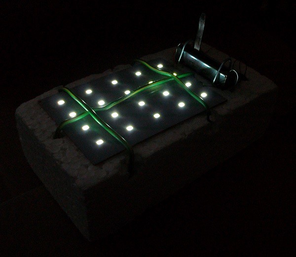
You can see my device working in the video:
I ordered a USB solar charger from China. It took a long time to arrive but when it came it was a kit. There were missing parts. There was no wire to attach the solar cell to the USB power supply and the rechargeable battery was missing. I figured I could use the USB power supply if I connect it to wind generator. I could not find a use for the bright LED that came with the kit.

Yesterday I found this article on https://instructables.com:
https://www.instructables.com/id/Cheap-Colour-Lights/
Step 1: Design the Circuit
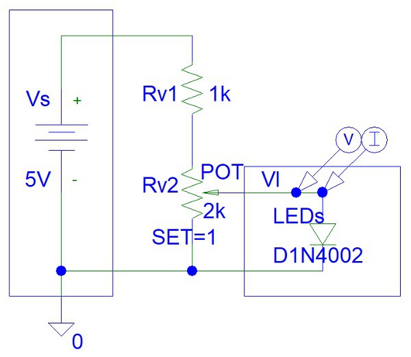
I drawn the following circuit on PSpice student edition:

The method for calculating the maximum LED current is explained in the Instructable.
Step 2: Build the Circuit
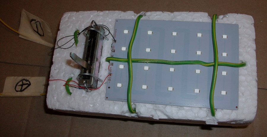
I chosen Rv1 as only 100 ohms because my power supply is 3 volts. You cannot see it in the photo because it is behind the potentiometer. Rv2 is an 2 kohm resistor that I had for many years from an old appliance that I taken apart many years ago.
My hobby solder would not stick to PCB tracks and the holes were very small. Thus I used wire wrap wire.
i attached the circuit to foam packaging material piece with high power insulated wires and attached the potentiometer to the packaging foam piece with 2 mm metal wire bits.

You can see that in the video that the connections are not very reliable.
Probably I should have tried drilling the holes to make them wider or using solder flux to allow sticking of solder to the PCB tracks.
 Recycled Planets
Discussions
Become a Hackaday.io Member
Create an account to leave a comment. Already have an account? Log In.