 Simple Components
This website shows simple test LED circuit that you can use to detect DC or AC small voltages. The AC signal will cause the LED to blink unless the frequency is above 100 Hz.

You can also use a 1.5 V light bulb because 1.5 V light bulbs can turn on at voltages less than 2 V. However, many companies are not producing light bulbs anymore. Light bulbs need higher currents than LEDs. A typical 1.5 V light bulb need 300 mA current that is 30 times more than a typical LED current of 10 mA. You can also purchase LED light bulbs. However, those components also need voltages of at least 2 V.
Step 1: Design the Circuit
I drawn the circuit with the old PSpice simulation software:

Calculate the maximum Vl value:
Vlmax = Vd * 5 = 0.7 V * 4 = 2.8 V
Calculate the maximum LED current:
Iled = (Vlmax - Vled) / Rled = (2.8 V - 2 V) / 100 ohms = 8 mA
Reducing Rled in half will increase the LED current to 16 mA value that might eventually burn the LED. A good alternative is to use a bigger LED that can dissipate 20 mA current.
Calculate the input current if Vs = 12 V:
Iin = (Vs - Vlmax) / R1 = (12 V - 2.8 V) / 100 ohms = 9.2 V / 100 ohms = 92 mA
Simulations:
The maximum Vl voltage is approximately 2.8 V as predicted:

Step 2: Make the Circuit
I used a soldering iron to create the circuit.

You can see that the resistor values shown in the circuit above are not the same as the ones that I used.
R1 is:
First Digit: Yellow = 4
Second Digit: Purple = 7
Number of Zeros: Brown = 1
R1 = 470 ohms
The other two resistors are connected in series to make the Rled resistor:
First Digit: Brown = 1
Second Digit: Red = 2
Third Digit: Black = 0
Number of Zeros: Black = 0
Rled = 120 ohms * 2 = 240 ohms

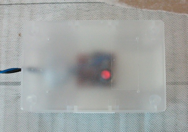
Step 3: Test the Circuit
I used a power supply and applied to following voltages to my circuit:
2 V:

2.5 V:
3 V:

3.5 V:

4 V:

4.5 V:

Discussions
Become a Hackaday.io Member
Create an account to leave a comment. Already have an account? Log In.