-
Big Audio Plug
10/25/2021 at 02:38 • 0 commentsWhen you make an audio amplifier you often want to test the circuit before putting it in the box or encasement. The encasement procedure involved connecting wires to plugs and sockets.
This short article is about making connecting your circuit to an audio plug that is part of the testing procedure.
![]()
What you see in the photo is a 6.5 mm stereo audio plug.
Step 1: Make the Circuit
You can see that I included two 2 Watt 10 ohm resistors. Those resistors protect the audio output from short circuits.
![]()
Bottom view:
![]()
Conclusion
Although a 10 ohm resistor will protect speaker and earphone outputs from short circuits, it will not be sufficient to protect the line outputs from short circuits. You will need to use a 1 kohm resistor instead.
-
Test LED
05/06/2020 at 09:47 • 0 commentsThis website shows simple test LED circuit that you can use to detect DC or AC small voltages. The AC signal will cause the LED to blink unless the frequency is above 100 Hz.
![]()
You can also use a 1.5 V light bulb because 1.5 V light bulbs can turn on at voltages less than 2 V. However, many companies are not producing light bulbs anymore. Light bulbs need higher currents than LEDs. A typical 1.5 V light bulb need 300 mA current that is 30 times more than a typical LED current of 10 mA. You can also purchase LED light bulbs. However, those components also need voltages of at least 2 V.
Step 1: Design the Circuit
I drawn the circuit with the old PSpice simulation software:
![]()
Calculate the maximum Vl value:
Vlmax = Vd * 5 = 0.7 V * 4 = 2.8 V
Calculate the maximum LED current:
Iled = (Vlmax - Vled) / Rled = (2.8 V - 2 V) / 100 ohms = 8 mA
Reducing Rled in half will increase the LED current to 16 mA value that might eventually burn the LED. A good alternative is to use a bigger LED that can dissipate 20 mA current.
Calculate the input current if Vs = 12 V:
Iin = (Vs - Vlmax) / R1 = (12 V - 2.8 V) / 100 ohms = 9.2 V / 100 ohms = 92 mA
Simulations:
The maximum Vl voltage is approximately 2.8 V as predicted:
![]()
Step 2: Make the Circuit
I used a soldering iron to create the circuit.
![]()
You can see that the resistor values shown in the circuit above are not the same as the ones that I used.
R1 is:
First Digit: Yellow = 4
Second Digit: Purple = 7
Number of Zeros: Brown = 1
R1 = 470 ohms
The other two resistors are connected in series to make the Rled resistor:
First Digit: Brown = 1
Second Digit: Red = 2
Third Digit: Black = 0
Number of Zeros: Black = 0
Rled = 120 ohms * 2 = 240 ohms
![]()
Step 3: Test the Circuit
I used a power supply and applied to following voltages to my circuit:
2 V:
![]()
2.5 V:
![]()
3 V:
![]()
3.5 V:
![]()
4 V:
![]()
4.5 V:
![]()
-
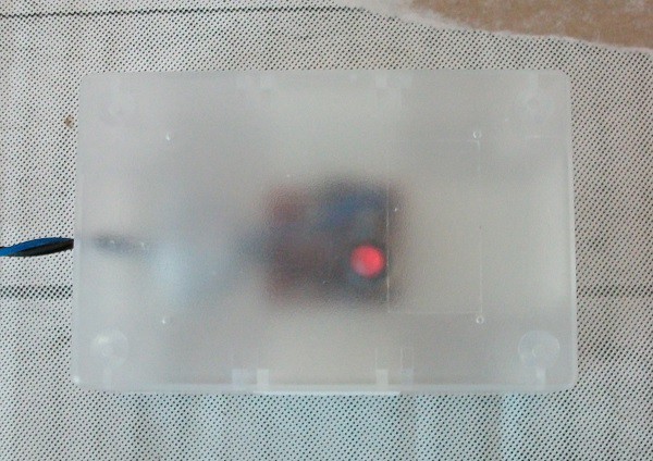
Simple Cooking Timer
04/28/2020 at 05:44 • 0 commentsThis article shows you how you can make a simple cooking timer.
![]()
You can see my circuit working in this video:
Step 1: Design the Circuit
I designed a simple RC (resistor-capacitor) charging circuit and simulated with PSpice simulation software:
![]()
The voltage-controlled switch is implemented with a push button in a real-life circuit. The switch and the LED are used to reset the timer by discharging the C1 capacitor to zero volts.
Calculate the time constant:
t = R1 * C1 = 47,000 ohms * 1,000 uF = 47 seconds
After five time constants, the C1 capacitor is considered to be fully charged:
Fully Charge Time = 5 * t = 5 * 47 seconds = 235 seconds
Calculate the maximum LED current:
IledMax = (Vs - Vled) / Rled = (9 V - 2 V) / 1,000 ohms
= 7 V / 1,000 ohms = 7 mA
Calculate the maximum power dissipation across the R1 resistor:
Pr1Max = Vs * Vs / R1 = 9 V * 9 V / 47,000 ohms
= 0.00172340425 W = 1.72340425 mW
The pulse width is 300 (< 235 seconds fully charged time) seconds (from 50 seconds (delay time) to 350 seconds). You can see that the C1 capacitor is fully discharged at 550 seconds:
![]()
Simulations show a maximum LED current of 7 mA.
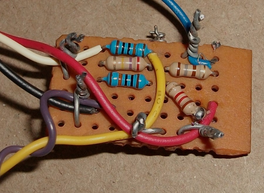
Step 2: Build the Circuit
I implemented the R1 resistor with three resistors because I did not have a 47,000-ohm resistor. Three resistors are also useful for shared power dissipation when the C1 capacitor is a short circuit.
You can read the colour codes of the two blue resistors:
Brown = 1
Black = 0
Black = 0
Orange = 3 zeros
(resistor colour code readings)
This is equivalent to 100,000 ohms.
I did not have the exact resistors that I needed. The Ro resistor is 180 ohms instead of 100 ohms:
Brown = 1
Grey = 8
Brown = 1 zero
(resistor colour code readings)
The Rled resistor is 1,200 ohms:
Brown = 1
Red = 2
Red = 2 zeros
(resistor colour code readings)
I only used a soldering iron to fix the 1.2 kohm resistor because the pin broke. It was a recycled component. All other connections were made by twisting the wires together.
![]()
Note the 33,000-ohm resistor across the LED:
![]()
Step 3: Test the Circuit
I used a simple op-amp voltage follower circuit (that you can see in my video) because my analogue voltmeter had an input resistance of just 12 kohms or 12,000 ohms.
The video recording that you saw above was done with my old iPhone 6. I used metal wire as a mobile phone holder and an LED desk lamp.
![]()


 Konrad Klepacki
 Taiwo
Taiwo Giulio Pons
 Ryan Kinnett
 John
John Andrés Lopez Pulzovan
 Clovis Fritzen
 robert
 Chaz
Chaz Roman Weitendorf
 Jeremy S. Cook
 smartroad
 Isaac Hayes
 naguirre
 kamahalanmark