 Xark
XarkRecently, I have been working with the iCE40UP5K FPGA on my Xosera video project for the rosco_m68k. My main development board for this project has been the iCEBreaker FPGA board from 1BitSquared (which is an excellent board). However, I also wanted to support a lower cost, smaller board that might be more suitable for "embedding" in the video project, so I was also planning to support the Upduino FPGA board that uses the same FPGA (which is fully supported by the open-source FPGA toolchain).
Frustratingly, I found that my design which worked fine on the iCEBreaker wasn't working at all on the Upduino (with appropriate I/O pin changes etc.). After some debugging, I determined that the PLL was having issues (the "PLL lock" signal would not stay on reliably indicating the PLL was "not happy"). A short time after discovering this issue I found this article on the (current) Upduino 2.1 maker's blog which seemed to explain my trouble: Ground trampolines and Phase Locked Loops (basically design flaws in the Upduino 2.x board keep the PLL from operating reliably).
The original Upduino 1.0 board was pretty amazing when it came out for $9.99, however it had some issues with how it was shipped and it was inconvenient to use (with no JTAG or external oscillator) and also poor electrical design. A while later, the design was updated to the Upduino 2.0 which had FTDI JTAG (and 12Mhz oscillator) added and a few other features. This was a nice improvement, but apparently this board also had a very poor electrical design (rumored to be designed by a student).
While hanging out on the rosco_m68k Discord, working on my video project Xosera, I met another 68K and FPGA enthusiast Claude. We had some discussions about FPGA video, and the Upduino FPGA board and it's issues (he was aware of the PLL issues and had improved his board with some "user modifications"). He was also playing around with some FPGA video projects and posted an amazing DVI hack he did on Twitter showing the iCE40UP5K directly outputting DVI video using an Upduino 2.0 FPGA board. This was enough to get the attention of the current Upduno 2.1 maker
Venkat took over the Upduino project from the creator and has been selling the Upduino 2.1 on Tindie (which was however, using the same flawed 2.0 electrical design). When he first took over, he sent an invite to buyers inviting them to fill out a survey to see how Upduino could be improved in an upcoming version. He seems to have done everything possible to accommodate everyones wishes where possible with Upduino 3.0 (as well as addressing the underlying electrical design issues).
Copying from the Upduino 3.0 GitHub wiki and Tindie page, here are some improvements over Upduino 2.x:
- Board:
- Lattice UltraPlus ICE40UP5K FPGA with 5.3K LUTs, 1Mb SPRAM, 120Kb DPRAM, 8 Multipliers
- 4 layer board, solid ground plane, dedicated power layer for 3.3V and 1.2V distribution
- All FPGA pins including LED driver pins are brought to 0.1" headers
- Any optional bridges must be done using special bridge-type footprint instead of resistors to make modification easy
- All passives to be no smaller than 0603 footprint
- Fix silkscreen so its easy to read, add Pb Free, WEEE symbol, "Made in USA"
- Move Micro USB connector inboard a little bit to allow clean depanelization
- Open source schematic and layout using KiCAD design tools
- Power
- Dedicated power and ground planes
- Minimum of 10uF bulk capacitance on all power rails: USB, 3.3V, 1.2V
- Dedicated decoupling capacitance on each FPGA pin placed close the FPGA pin
- Power decoupling per FTDI recommendations (using ferrite beads)
- Change LDO's to be smaller parts, capable of 200mA max output
- Oscillator:
- 12MHz crystal oscillator to replace the resonator for stability
- Access to on-board 12MHz oscillator using a jumper (short R16)
- Flash
- qSPI capabile: Short R24, R25
- 4MB SPI Flash
- DTR capable flash to support even higher throughput
- Programming:
- Connect DONE signal to the FTDI
- FPGA CRAM programming capability
- tinyFPGA bootloader compatible (short R22/R23/C26, install 1.5K on R21, open R35/R36)
- LED:
- Smaller 3 color LED
- Bring out the 3 color LED pins to allow these to be used for other applications such as IR LED's etc.
So, long story short (oops, too late), the Upduino 3.0 board is looking like a winner for a low-cost ($24.00) breadboard friendly iCE40UP5K board to me. I have been able to run all the designs I have tried without issue and the board has worked great (including PLL using designs, that were problematic on Upduino 2.x).
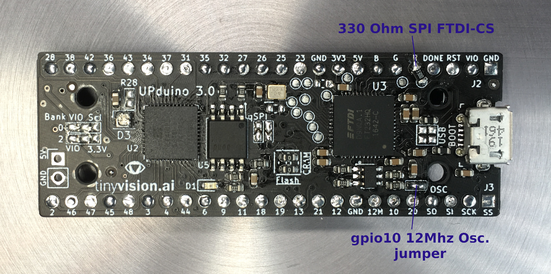
Here is a picture of my Upduino 3.0 preproduction board. You can see I have added a 330 Ohm SMD resistor that connects "TP11" (which is FTDI ADBUS3, aka CTS#) to the red RGB LED pin. This is used as SPI target CS so a PC via FTDI can control the FPGA as a SPI target device (in addition to UART communication - but one at a time). I have also shorted the OSC jumper (R16) that connects the 12Mhz external oscillator to FPGA gpio10 (if you don't do this, you will need to route 12M pin using an external wire into gpio35 for a stable clock, similar to Upduino 2.x).
 VERDICT: Upduno 3.0 looks to be a very nice open-source and breadboard friendly low-cost FPGA board!
Discussions
Become a Hackaday.io Member
Create an account to leave a comment. Already have an account? Log In.
Hey, sorry for the slow response. I did eventually get the UART working, but only by using a different UART from github (https://github.com/jakubcabal/uart-for-fpga). The one linked to above wouldn't synthesize - something to do with the util.v file. I guess from your perspective the take away is that the board can be used with the FT232H for a UART interface. I feel like there's room for improvement (particularly sharing the SPI flash pins) but at the price point it's okay.
Are you sure? yes | no
Cool, glad you got it working. It might be nice if UPduino used FTDI F2232H which has 2nd UART channel, but as you mention it was aiming for low-cost. If needed, you can also use an additional FTDI serial module on GPIO pins and dedicate that for UART use.
Are you sure? yes | no
Hello,
The UART "works fine" using FT232H on UPduino I believe, but it does share pins with SPI flash so you can't make a design that uses the built in UART and also accesses SPI flash (basically make sure you pull pin 16 spi_ssn/spi_cs HIGH, to keep SPI flash disabled when using UART). I believe this example will work with UPduino v3.x:
https://github.com/osresearch/up5k/blob/master/serial-echo.v (as well as other examples there, v2.x is subset of v3.x).
One other potential minor issue is that on some OSes, you need to unplug and re-plug UPduino after programming to get normal USB serial driver to work (after FT232H was in "JTAG mode").
Are you sure? yes | no
Hi, I have bought version 3.1 and I quickly found this page. Your article is the closest I've found to someone implementing a UART interface to the FPGA, but it's not obvious to me how it would work given the schematic. The FT232H datasheet suggests that when configured as a UART it is the ADBUS pins that are used. So then it looks like we have to re-purpose the FT_SCK and FLASH_MOSI pins, linking them back into GPIO with some soldering. In UART mode, pin 17 to the FT232H (DTR#) will be active, thus driving FT_SSn low and messing around with the EEPROM. Is the solution to use the FT_PROG utility to enable the ACBUS outputs and solder the relevant TPs to GPIO?
I'd be grateful for any tips or guidance you have on this, because unlike the Lattice Ice Stick or IceBreaker, this board doesn't look geared up for a UART interface, even although all of the literature suggests it is.
Thanks, Ryan
Are you sure? yes | no
Did you ever find an answer/solution to this? I'm trying to port the board to LiteX, and this is the one thing preventing me from making a pull request.
Are you sure? yes | no