 Crazy Electrical
I made the following mechanical system with three driving DC motors and one generating DC motor:
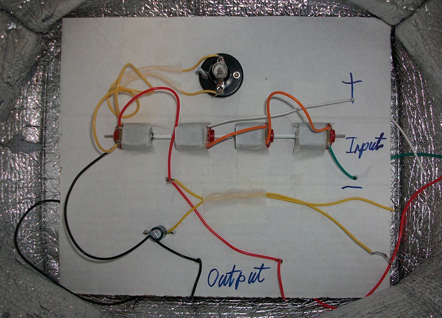
You can reverse the polarity of the input and the light bulb will still turn ON. I only specified the polarity of the input because the output capacitor is not bipolar and reversing polarity and motor direction will reverse the output current flow. I used three motors to drive the rotating shaft because the input is 9 V, not 3 V. However, the potential difference across each motor can exceed 3 V at certain shaft rotating cycle positions. A good solution to this problem is connecting a capacitor across the inputs of each of the 3 shaft driving motors. However, I did not bother with the time and the money.
Videos
You can see that the 1.5 V light bulb is blinking non stop without the capacitor:
With output capacitor (wire terminals shorted) the blinking was not so sudden:
USB Oscilloscope Readings
The motor output is showing a lot of noise and is high frequency because the motor is rotating at fast speed:

I tried zooming in on the acquired data:

The readings show how the capacitor can filter the generated output signal:

Discussions
Become a Hackaday.io Member
Create an account to leave a comment. Already have an account? Log In.