-
Battery Charger
12/28/2021 at 03:44 • 0 commentsWe all know that NiCad batteries need to be fully discharged before they are charged to prevent failure.
Thus I designed a circuit that does exactly that.
This is how you use this circuit.
1. Insert the battery.
2. Straight away turn ON the discharging button.
3. Wait until the battery discharges and then begins to charge on its own.
You just need to press the discharge button. The circuit will do the rest.
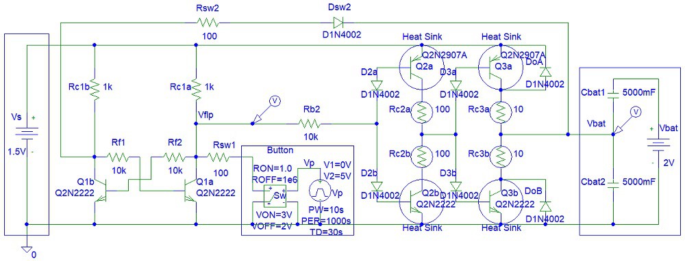
Step 1: Design the Circuit
I have drawn the circuit in PSpice simulation software student edition to save time.
![]()
You can see that I used a flip flop to switch between two states. Charge and discharge. You might need to use four transistor pairs instead of two transistor pairs for the battery driving circuit (Q2 and Q3 transistors). Also, you will need to use power transistors, not the general-purpose transistors that I used. The student edition does not include power transistors and allows only a limited number of components in the circuit.
If you making a 9V battery charger then you can use MOSFETs.
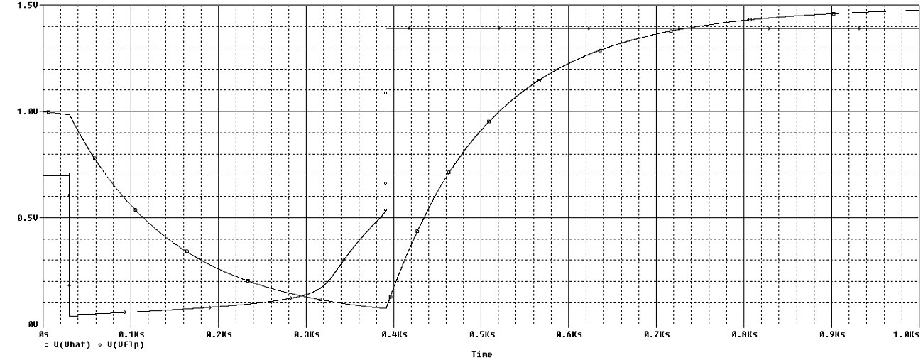
Step 2: Simulations
You can see how the battery is first discharging after the button is pressed and then begins to charge after the voltage falls to approximately 0 V:
![]()
Conclusion
I modeled the battery with two capacitors. This might not be true in real life.
-
Diode Power Mixer
01/20/2021 at 04:32 • 0 commentsThis article is about a diode power mixer circuit.
![]()
The circuit shown in this article is not the best way to mix two or more power signals. An alternative circuit is shown in this link:
https://electriccircuits.yolasite.com
I used the following diode IC (integrated circuit):
https://www.digchip.com/datasheets/parts/datasheet/513/MBR1545CT-pdf.php
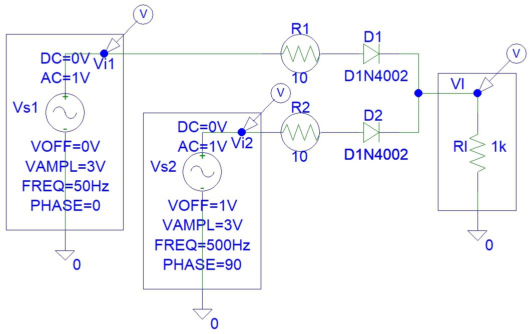
Step 1: Design the Circuit
I have drawn the circuit in PSpice student edition simulation software:
![]()
The drawing above is not showing the dual Schottky Diode IC (integrated circuit) that I used instead of two diodes (D1 and D2), because the student edition does not have this component in the list. Schottky diodes have lower forward bias voltage drop than typical silicon, germanium, or point contact diodes.
Step 2: Simulations
Simulations show how the circuit will work:
![]()
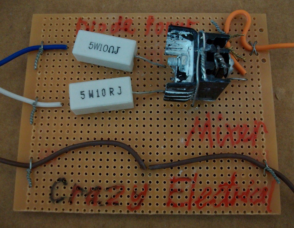
Step 3: Make the Circuit
I used soldered the components onto the matrix board:
![]()
Step 4: Testing
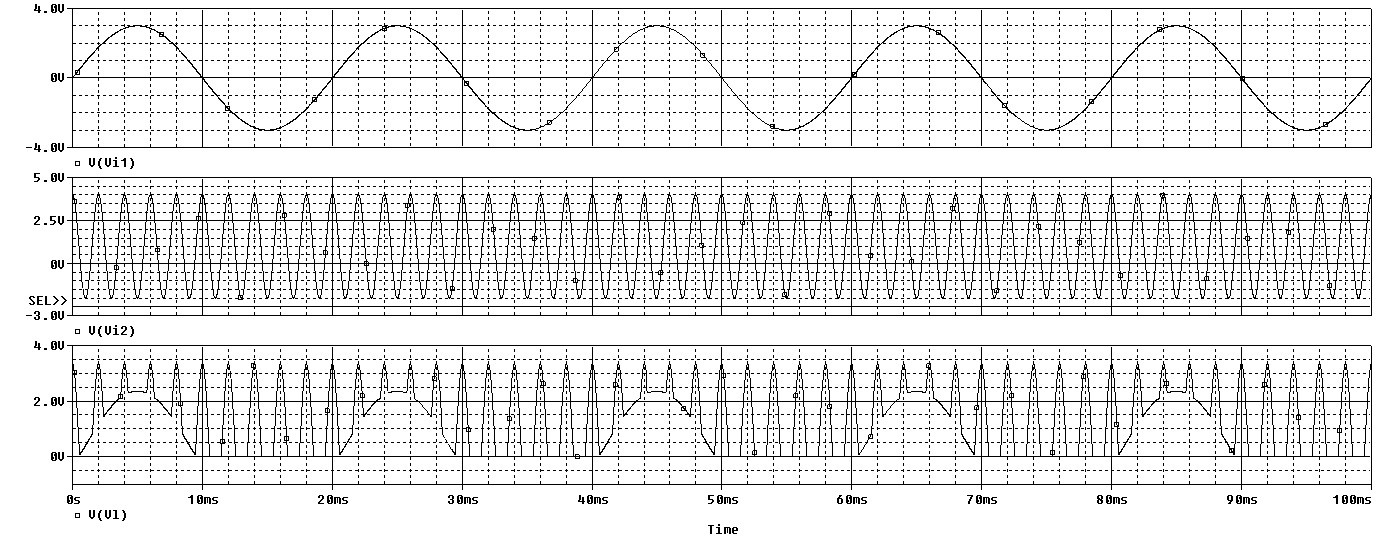
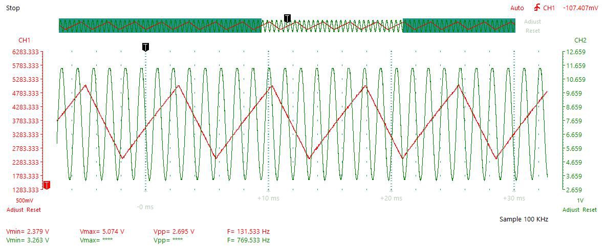
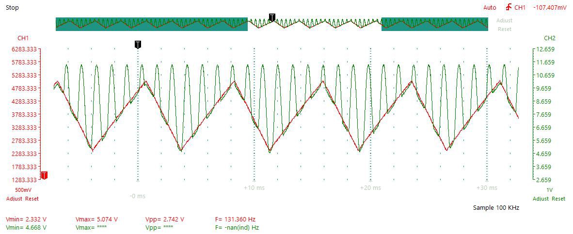
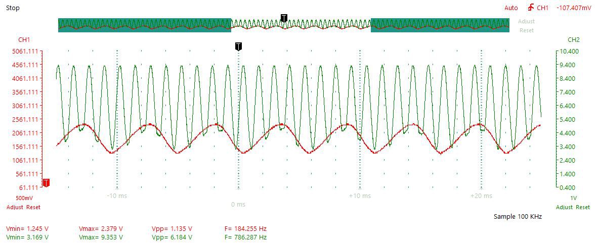
I used a benchtop signal generator (for the first channel), 8038 signal generator circuit (for the second channel), and Instrustar USB oscilloscope for testing.
Input signal:
![]()
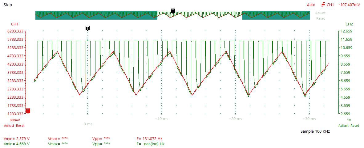
Triangle and Sine Wave:
![]()
Two Sine Waves:
![]()
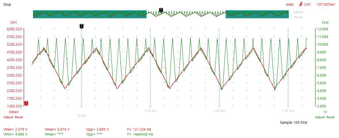
Triangle and Square Wave:
![]()
Two Triangle Waves:
![]()
Conclusion
There is an option of eliminating the DC component with the RC (resistor-capacitor) high pass filter. However, this is not a good idea if you are making a power supply.
References
-
Motor Power Converter
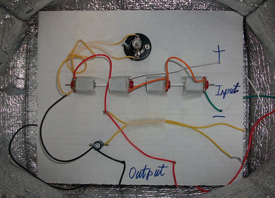
08/27/2020 at 10:17 • 0 commentsI made the following mechanical system with three driving DC motors and one generating DC motor:
![]()
You can reverse the polarity of the input and the light bulb will still turn ON. I only specified the polarity of the input because the output capacitor is not bipolar and reversing polarity and motor direction will reverse the output current flow. I used three motors to drive the rotating shaft because the input is 9 V, not 3 V. However, the potential difference across each motor can exceed 3 V at certain shaft rotating cycle positions. A good solution to this problem is connecting a capacitor across the inputs of each of the 3 shaft driving motors. However, I did not bother with the time and the money.
Videos
You can see that the 1.5 V light bulb is blinking non stop without the capacitor:
With output capacitor (wire terminals shorted) the blinking was not so sudden:
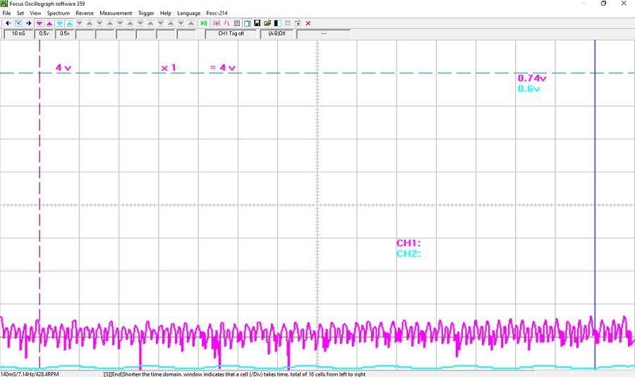
USB Oscilloscope Readings
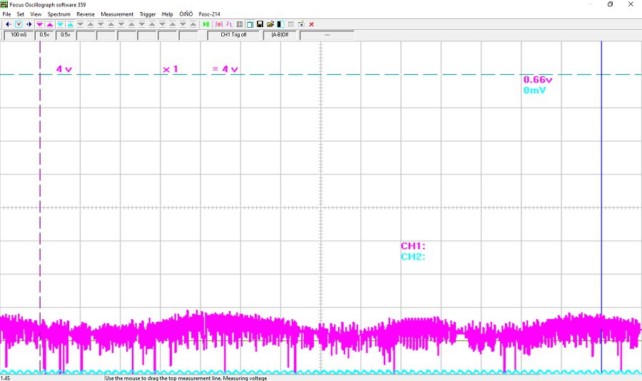
The motor output is showing a lot of noise and is high frequency because the motor is rotating at fast speed:
![]()
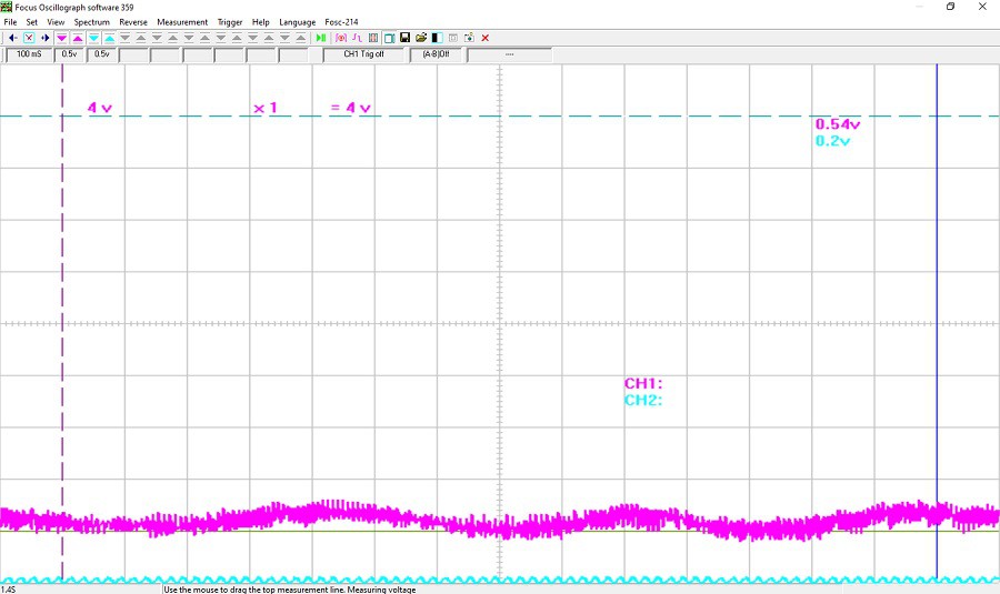
I tried zooming in on the acquired data:
![]()
The readings show how the capacitor can filter the generated output signal:
![]()

 Kuldeep Singh Dhaka
 Dr.Query
 doctek
 Christoph Tack
 Philip Zucker
 Andrés Lopez Pulzovan
 John Opsahl
 Israel
 borazslo
 Angkan Gayen
 Juin Lee
 hIOTron
 Daren Schwenke
 Aditya Mukherjee