 Electronic Circuits
This article shows a simple n-channel MOSFET sensor amplifier.
The sensor output is could be either a biased/non-biased sensor or a pre-amplifier amplifier output.
The power MOSFET that I used is also able to drive high power/current loads (bright LEDs/light bulbs/motors/relays).
The 1 Megohm potentiometer provides a variable voltage divider source to the MOSFET gate pin. As soon as the MOSFET gate voltage reaches a specific minimum threshold, the MOSFET turns ON and provides current to the load that is connected to the MOSFET drain pin. The source of the n-channel MOSFET is grounded or connected to a negative battery lead.
The potentiometer can be adjusted just on the edge of triggering which will allow non-linear but reasonably high amplification of changes in sensor output voltages.
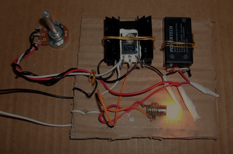
You can see in my circuit that the sensor output (white wire) is connected to the MOSFET gate via 10 kohm resistor to ensure that the potentiometer does not short the sensor output when it is set to zero MOSFET gate voltage.
Calculations for selecting a heat sink are explained in this link:
https://www.instructables.com/Component-Heat-Dissipation
1. Videos
Tuning:
I connected the input to my signal generator:
2. Testing
I used a 12 V light bulb and 9 V battery believing that my power MOSFET could handle the 9 V maximum gate pin voltage.
Night time photo:

I connected the input to the signal generator and increased the frequency:
3. Conclusion
A significant amplification might be required before the sensor output signal enters my MOSFET circuit to achieve a proper sensitivity of the sensor circuit.
Discussions
Become a Hackaday.io Member
Create an account to leave a comment. Already have an account? Log In.