INTRODUCTION:-
We all have seen vu meters in every music system and various other recording devices but never wondered to create such a thing ,so today I am going to tell you a simple and easy way by which you can create a simple vu meter by your own which will react to music and other small sounds but it all depends on the quality of mic used.
Simple vu meter kits are available on every e commerce sites at a cheap price but if you have an Arduino uno do could do more with it just making a vu meter. So here we are going to make a simple vu meter which you can make use in something more attractive and bigger task like changing color of RGB light.
DESCRIPTION:-
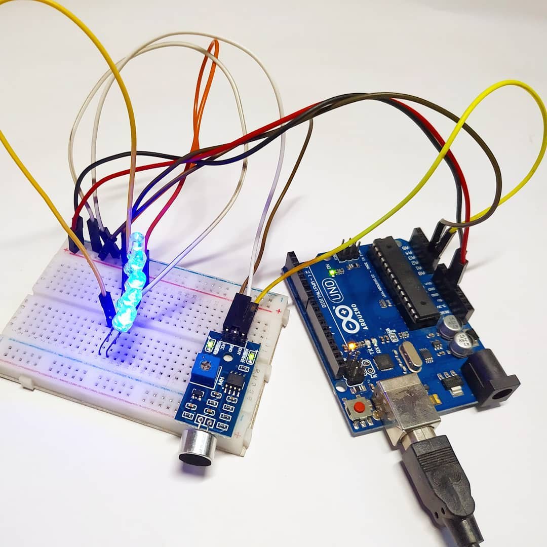
Here we are going to use some of the common components that every robotics hobbyist will have. In this we are going to use sound sensor which is built out of LM358 ic a condenser microphone a variable resistor to trim the values of range of the value given by the sensor to the microcontroller.
Sensor also has an onboard power led and also an onboard Status led which will blink whenever the sensor detects some sound
The sensor gives analog output which varies according to the sound input in the microphone also on the variable resistor as LM393 amplifies the sound acc to the variable resistor value.
*NOTE:- THIS SENSOR IS BASED ON CONDENSER MIC WHICH NOT A GOOD QUALITY ONE I RECOMMECD YOU TO USE THIS MIC FOR SOMR COMMON PROJECT BUT IF YOU WANT FOR AN PROFESSIONAL ONE I RECOMMEND YOU A GOOD QUALITY MICROPHONE AND AN BETTER AMPLIFIER IC.
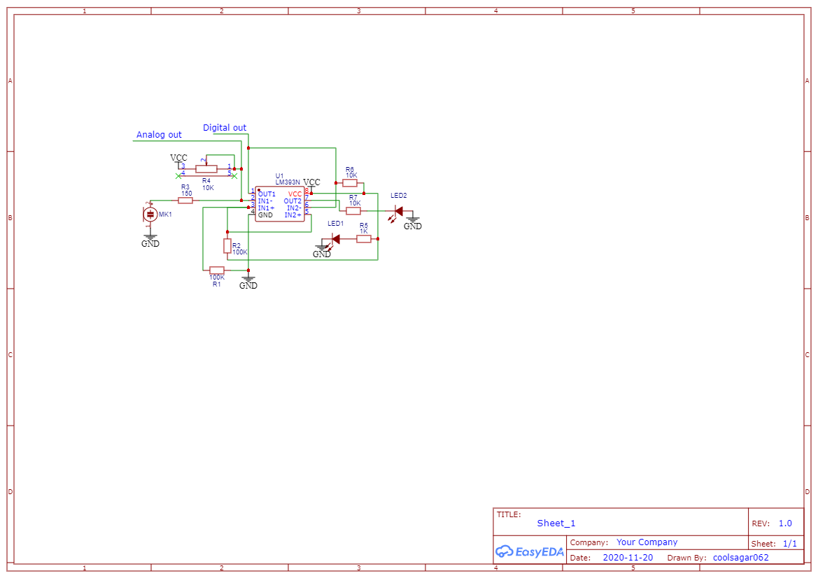
SCHEMATIC DIAGRAM:-
FEATURES AND APPLICATIONS:-
- Sensitivity of sound is good
- Easy to use
- Adjustable value
- Low price
- Can be used in small projects and vu meter devices
SENSOR SPECIFICATIONS:-

COMPONENTS NEEDED:-
- Any microcontroller preferably Arduino Uno for beginners.
- A bunch of different led but of same voltage
- A sound sensor
- A breadboard
- Jumper wires
- 220ohm resistor
CIRCUIT DIAGRAM:
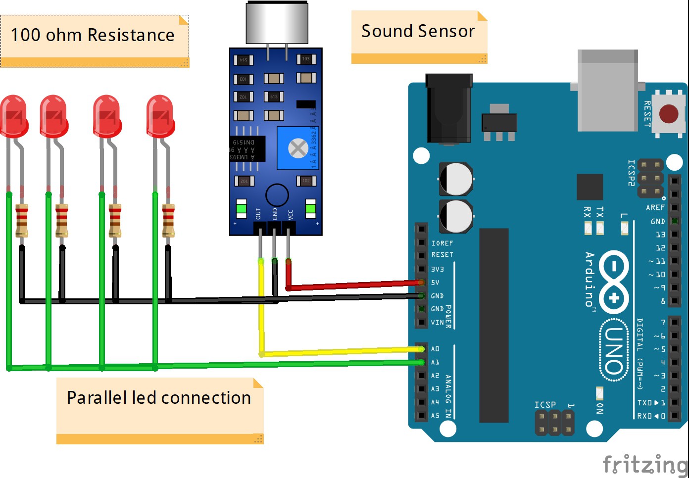
First take the power lines onto the bread board from microcontroller
VCC/5v-->+ line and GND--> - line.
Then connect the sensor on to the bread board and connect power to the sensor from powerlines using jumper wires.
Now connect OUT PIN OF SENSOR TO MICROCONTROLLER ANALOG
PIN A0.
Now connect leds to the breadboard – to gnd and + wire to analog pin A1 in series with a resistor to the microcontroller.
CODE:-
//put this code in the ide of arduino from this line
int val;
void setup()
{
Serial.begin(9600);
}
void loop()
{
val=analogRead(A0); // Sound Sensor connect A0 pin
Serial.println(val);
delay(50);
val=map(val, 0, 1023 , 0, 225);
analogWrite(A1, val); // led connect A1 pin
}
WORKING:-
As the code starts it initializes the pin to which the sensor sends its data then the microcontroller waits for the data to be received as soon as the data is received it then maps its value from 0-1023 to 0-255 which is analog output limit.
After it maps the value in val it then sends this value in the form of output range to the anlog pin A1 for the leds to react.
PCB DESIGNING:-


Now as we have developed our circuit and ordering it. For ordering PCB, I would prefer you NextPCB which is a great website for ordering custom PCB with high quality and precision on time delivery. Ordering PCB online in various sites are a step towards developing our own circuit. NextPCB provides very easy and fast delivery of PCB in different masks and paste with professional look. Also, they send you the picture of your PCB before shipping it to you, Now that very exciting….The Gerber File for the PCB is given below. You can simply download the Gerber File and order the PCB from :Gerber Viewer of NextPCB
Go to get your discount: NextPCB
#arduino #arduinouno #arduinoproject #arduinomega #arduinonano #arduino duo
Discussions
Become a Hackaday.io Member
Create an account to leave a comment. Already have an account? Log In.