 Recycled Circuits
This website is about an ultrasonic LED circuit:
The LED can be replaced with a bright LED that emits a higher light intensity.
You can see the circuit working in the video below:
I used the following transmitter connected to Dick Smith Electronics (DSE) signal generator:

Step 1: Design the Circuit
I drawn the circuit in PSpice student edition software:

Calculate maximum LED current:
IledMax = (Vs - Vbe3 - Vce2sat - Vled) / Rd
= (9 V - 0.7 V - 0.2 V - 2 V) / 1000 ohms
= 6.1 V / 1000 ohms
= 0.0061 A = 6.1 mA
This current value is very small. You can increase the current by reducing Rd value to:
Rd = 560 ohms: IledMax = 6.1 V / 560 ohms = 10.89285714 mA
or
Rd = 470 ohms: IledMax = 6.1 V / 470 ohms = 12.9787234 mA
The current for the big LED shown in the photo should be 20 mA. However, if you are using recycled LED components, then you might end up with an LED that will burn at currents above 5 mA.
Step 2: Simulations
Time Domain:

Frequency Domain:

Step 3: Transistor Testing
This is the transistor testing circuit that I used because I only had one LED in stock:

I used to 100 ohm resistors as metal wires.
Video:
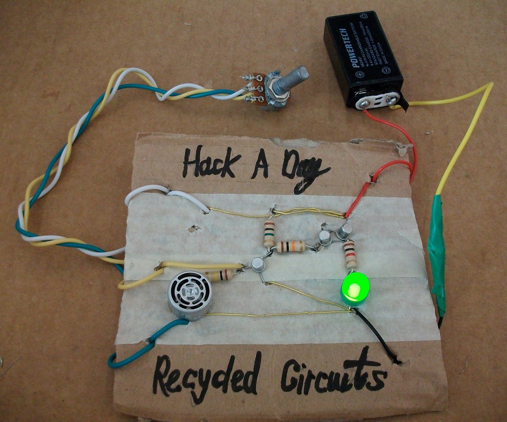
Step 4: Make the Circuit
I made the circuit without the use of the soldering iron:

You do not need to use 1 Watt resistors for this circuit that you see in the photo above. The 250 mW power rating will be sufficient for this circuit.
I used 1 Megohm value for Re1 resistor instead of 100 kohm shown in my circuit design to obtain a higher gain. The difference is not significant. I specified the 100 kohm Re1 resistor because most resistors came in a pack of five or two, thus eliminating the need for searching or buying another resistor (the 1 Megohm).
Step 5: Testing
This video shows brightness control testing:
Proximity sensor mode testing:
Discussions
Become a Hackaday.io Member
Create an account to leave a comment. Already have an account? Log In.