-
How to Install a Fusible Link?
04/21/2022 at 10:06 • 0 commentsUnlike a circuit breaker, all fusible links can't be reset and need to be replaced once it is blown. Take the following guidelines to replace it by yourself.
Materials to prepare:
- New and Proper Size Fusible Links
- Wire Cutter
- Wire Stripper
- Heat-shrink tubes
- Solder
- Soldering Gun
- Heat Gun
- Wire Crimps
![]()
- Dismount the negative pole of the battery
- Cut off both ends of the blown fusible links from the main wire harness
- Strips the ends of the new fusible link for 1-2 inches
- Blend the stands of copper of one end of fusible links with the main wire
- Puts crimps onto the connecting point and solder it to build a stronger connection
- Slide the heat shrink tube to cover the joint area
- Use the heat gun to fasten the heat shrink tube
- Repeat 4-7 for the other end of the fusible links
(Originally posted on Easybom)
-
How to Test a Relay
04/21/2022 at 10:02 • 0 commentsTake this 4 pin NC relay as an example; you can test a relay with a multimeter in the following steps:![test rely coil circuits]()
1. Turn off any power load to the relay
2. Set the multimeter to 2KΩ resistance mode
3. Attach the probes with two coil contacts of the relay
A standard 12V relay has a coil resistance of around 50~200 ohms.
![test conducting contacts]()
4. Switch the multimeter to continuity mode (some DMM integrates it with the diode mode)
5. Connect the probes with both the COM contact (30) and the NO contact (87)
![supply coil contacts with load]()
6. Supply an independent power source to the coil terminations according to the relay ratings
![test second coil continuity]()
7. Keep the relay mounted with power and connect the meter probes with two switch contacts again.
(Originally posted on Easybom, Click to Read more)
-
What's the Difference between Managed and Unmanaged Switch
03/23/2022 at 03:25 • 0 comments![]()
Managed vs Unmanaged Switch: Which to Choose?
When packets reach network switches, they're compared against an inventory of addresses and network segments. If the segments are not compatible then packets are transferred and if not, they are blocked. Nodes with high traffic or mission-critical systems are often connected to an individual switch port.
When devices are linked to the switch the switch will record its media access control (MAC) address. It is a number encoded within the network interface card (NIC) that connects to an Ethernet cable that connects to the switch. The switch makes use of its MAC address in order to know which connected device is sending outgoing messages and the location to which packets from incoming ones should be sent.
Certain Ethernet solutions providers classify network switches as unmanaged and managed varieties. They differ from one to the other in a variety of ways.
What is the Managed Switch?
Managed switches can be called configurable switches because they are extremely configurable both for remote and local usage (which implies it's a good idea to outsource your network management). The primary benefit of managed switches managed switch is that its configurations can be modified to meet your particular requirements for managing your network. In addition, it comes with important features such as RSTP (Rapid Spanning Tree Protocol) as well as CLI (Command Line Interface), and many more.
They offer a level of security that unmanaged switches cannot for you are able to select the best operation for each port. They can instantly shut down identified threats, prevent access from unwanted sources and even encrypt communications as they monitor and manage the network's events.
Redundancy Protocols
Redundancy helps protect a network in the event of cables or links fail by providing a backup route for data. To ensure that integrated systems are running, standard protocols eliminate loops and permit redundant links to act as a backup. This will save you time and money and any user will be grateful for.
VLANs (Virtual Local Area Network)
One of the biggest advantages of a managed networking switch is the ability to divide local networks using VLAN. This means that it doesn't just fill MAC tables with data, but also provides information regarding the frame's connection to an individual network segment. This means that we can reduce excessive broadcast traffic, adjust access to devices for a particular subnetwork, and increase security.
QoS (Quality of Services)
It is a function that prioritizes bandwidth to data subsets, which allows for greater bandwidth to be shared over the network to ensure IP data flows seamlessly and sensor data can be accessed without interruption, using only a small amount of bandwidth.
SNMP (Simple Network Management Protocol)
SNMP is a protocol that permits network devices to collect information, arrange, and modify management data. Thus, without needing to physically inspect the switches or devices, IT administrators can examine the SNMP information and track the performance of the network from a distant location and even identify and correct network issues from a central point.
SFP (Small Form-factor Pluggable)
The advantage of SFP slots with multiple rates is the flexibility of the network that allows users to utilize 100Mbps and 1Gbps SFP Modules to use single-mode or multimode fiber-optic (or copper) depending on the requirements. If your requirements shift or your requirements change, the SFP module could be easily changed, allowing you to safeguard the investment you made in your switch.
---------- Read More: Managed vs Unmanaged Switch: Which to Choose?---------- -
Insights: Development Trend of Wafer Fabrication Industry
02/14/2022 at 03:05 • 0 commentsin the last two years in the past two years, the past two years, wafer production market has grown significantly because of the high demand for high-end processors in data and network centers, smartphones with 5G, and other applications that are growing rapidly like robotics, autopilot, AI, and other high-growth apps.
IC Insights report predicts that the total sales of the wafer manufacturing industry in 2021 will be above 100 billion dollars US 100 billion thresholds for the very first time in history, at the US $107.2 billion which is a rise of 23% as well as continuing to increase by an average rate per year of 11.6 percent. Total sales are expected to exceed US $151.2 billion by 2025.
![]()
As per SEMI Global semiconductor producers will construct 29 new factories between 2021 and 2022. Of 19, 19 of which will be constructed at 2021's end and 10 more by 2022 to meet the ever-growing demands for chip production.
As illustrated in the figure in the figure, looking from the perspective of regional distribution China and Taiwan will dominate the distribution of regional resources. China along with Taiwan will lead in the building of new plants. There will be eight each, followed by six in America as well as 3 in Europe and the Middle East, 2 in Japan, and two located in South Korea. Of the new plants, 300mm (12-inch) plants will comprise 15 of them in 2021 and seven in 2022.
Once all 29 facilities are complete and in production, the plants can produce upwards of 2.6 million wafers (equivalent to 8 inches) every month.
Based on the type of facility of category, all 29 of them are factories that produce wafers, with the capacity to produce 30 000 - 220000 wafers (equivalent 8 inches) and 4 are storage facilities with the capacity of between 100000 and 400000 wafers (equivalent 8 inches).
While overall capacity is increasing, the rate of expansion in capacity differs for different dimensions of wafers. As for proportion, 12 inches were the largest on the list with 8 inches accounting for just 4% of the total in 2020. It increased to 6% in the year ahead because of the absence of a core. This is expected to continue until 2022.
In actuality, the primary deficiencies this year-analog IC power management IC display driver IC and power components MOSFET MCU sensors, and the analog ICs are predominantly focused on the capacity of 8 inches and revealing the absence of capacity. Because the greater return on the investment in twelve-inch wafer manufacturing line capacity to produce 8 inches by manufacturing facilities has been reduced in recent years. as per the latest statistics, it is unlikely that this will be significantly altered by this year's shortage. According to the SIA forecast that the world's 8-inch wafer production capacity will increase by just 17% between 2020 and 2024.
In contrast to the slow expansion of the foundry capacity of 8 inches 12 inches capacity expansion is extremely active and the annual compound growth rate is projected to be higher than 8 percent in 2022.
Since 2019, the utilization of capacity in fabs with 8-inch and 12-inch dimensions across the globe has increased, reaching 90% by 2020.
While all regions in the globe are growing production, there are noticeable variations in the process of manufacturing.
Despite the shortage of chips, chip suppliers have entered into contracts with contract manufacturers for several years, revenues of contract manufacturing companies increased by 22.6 percent to reach $95 billion by 2021. It will increase by 11.9 percent by 2022, however, the global capacity utilization will decrease. Gartner estimates that the rise in capital expenditure will cause a worldwide surplus of wafer capacity between 2024 and 2025. In addition, the utilization of factories will fall to less than 80 percent. A significant portion of this capacity growth stems from the growth of the fab. It requires...
Read more -
Vishay Improved Automotive Grade Thin Film Chip Resistors
02/09/2022 at 02:12 • 0 commentsVishay Intertechnology has widened the range of resistances of its MC AT precision series of automotive-grade thin-film chip resistors in the 0402 0303 and 0603 sizes of the case.
DC/DC converters as well as DC-Linking and voltage dividers in batteries management, on-wall, and onboard chargers, and power inverters trans-impedance amplifiers and e-compressors. networks.
Features
- Approved as EN 140401-801
- Superior temperature cycling strength
- AEC-Q200 qualified
- Advanced sulfur resistance has been verified in accordance with the ASTM B 809
- Rated dissipation P70 the range of 0.4 W for 1206 size
- Superior moisture resistivity, |DR/R| < 0.5 % (85 degC; 85 % RH; 1000 h)
Applications
- Industrial equipment
- Medical equipment
- Telecommunication
- Automotive
Additionally, they have excellent water resistance, superior thermal cycling robustness, as well as advanced sulfur resistance that is in line with ASTM B 809 standards, these devices are engineered to provide reliable performance in automobile and medical, industrial, and telecommunications equipment, even in extreme conditions.
---------- more on Easybom Blog---------- -
Nvidia Denies Abandoning its Acquisition of Arm
01/26/2022 at 02:30 • 0 commentsNvidia is "quietly" preparing to abandon its $40 billion acquisition of British chip designer Arm, Bloomberg reported on Jan. 25.
Nvidia shares closed down 4.5% on the day. In response to rumors of abandoning the acquisition of Arm, Nvidia responded to China Business News on January 26: "We continue to hold the view detailed in the latest regulatory documents-this deal will provide an opportunity to accelerate Arm and promote competition and innovation."
An insider told China Business News that the news reported by Bloomberg that "Nvidia told partners that the deal is not expected to be finalized in the end" is not true. Nvidia's acquisition of Arm has been closely watched by regulators around the world, who fear it will give Nvidia an unfair advantage in the semiconductor industry.
According to Nvidia's plan, the acquisition of Arm, a British semiconductor company, should be completed in March. However, the deal is still under review by global regulators, and Nvidia is likely to miss the March deadline. The US Federal Trade Commission sued last month to block the deal on antitrust grounds, while UK regulators are investigating the deal, fearing it could pose a threat to national security. Nvidia will also face multiple regulatory hurdles in China.
Earlier this month, Nvidia disclosed a 28-page written document submitted to (CMA), the UK's competition and market authority, setting out the reasons why regulators should approve the company's acquisition of Arm. In the document, Nvidia points out that opponents of the deal have mistakenly "romanticized" Arm's history and exaggerated Arm's market forces. The company said Arm's financial situation was not optimistic and needed more financial support. Capital markets expect Arm to make major strategic changes, including spending cuts and maximizing value.
Arm is widely regarded as a jewel in the crown of the British technology industry. The company's low-power chips are designed for 95 percent of the world's smartphones and 95 percent of chips designed in China, while Arm's chip design is licensed to more than 500 semiconductor manufacturing companies.
The acquisition was opposed by market participants including Intel, Qualcomm, and other giants, who argued that Nvidia's acquisition of Arm would undermine the company's independence and possibly raise prices, thereby limiting competitors' use of Arm patents and hampering innovation in the industry.
-
What to do with a Swollen Battery
01/21/2022 at 04:11 • 0 commentsThe Efficiency of Lithium-ion Batteries Comes at an Expense
There's no doubt that the lithium-ion battery is a well-tested and technique-proven option for electronic devices of today for industrial use as well as consumer electronics. From the massive battery of 4680 which will be used in Tesla EVs to the light, slim, and durable battery pack that you can put in your smartphone or wireless headphones They're everywhere.
The lithium-ion battery isn't flawless despite its numerous advantages, i.e., high density and long-lasting. As the battery age and the process for creating power can become faulty and result in a ballooning battery. Additionally, improper management and the use of patterns could be contributing factors to the problem.
![]()
What Causes The Battery to Swell?
The situation that comes with an over-saturated battery is similar to an overcrowded playground, where security methods are not in place. Furthermore, the unrestful particles within the layers of the battery react with the exterior air moisture, leading to the body of the battery becoming swollen. In the end, these causes frequently explain the problem.
Natural aging. Electrical equipment can last for a long time as well lithium-ion batteries. As time goes by the chemical reaction in the battery will not be as efficient when the battery is created. Additionally, the internal layers don't remain in a proper segregating condition of them. A typical lithium-ion battery should last for two to three years of use.
A cooling vest has been blocked (happens typically to laptops). If the vent of the cover of the port for filling up with battery is blocked, gas will slowly build up when the charging duration exceeds the recommended time or voltage of charging exceeds the recommended voltage. This will cause pressure inside the battery box and eventually result in a swelling of the battery.
Insufficient charging. This is the most frequently cited reason for the swelling of the battery. When the charging current for the battery is too high or the charging duration is too long, an excessive amount of gas is generated. Additionally, excessive current or an excessive amount of time to charge can also trigger a rapid rise in the temperature of the electrolyte. This can quickly bloat the battery.
A discharge that exhausts. Lithium-ion batteries may be bloated due to the discharge depth or defective BMS (battery management system).
Symptoms of a Swollen Battery
![]()
What can you do to identify a bulging battery? The best way to detect a swollen battery is to look at your device's exterior. For instance, if your laptop is beginning to show unnatural "curves" on the keyboard area. Your phone's aluminum frames loosen up and it isn't able to be placed in a uniform manner on the desk.
What should I do about My Swollen Battery?
Is a Swollen Battery Dangerous?
![]()
(an old man scratched and scratched an over-swollen battery, which ignited in a cell phone repair station)
Yes, absolutely. It is possible to harm the whole device, as the bulges in batteries generate temperatures. Not to mention that the change in shape can break the shell made of the metal container and trigger a short-circuit or even ignite. Additionally, the harmful outcast that is flammable from batteries made of lithium-ion is a threat to your home keeping, pets as well as human life.
Does it help shrink The Swollen Battery by freezing it?
No. Putting the battery in the refrigerator won't decrease the oxygen content of the battery, nor does it address the root issue of the lithium-ion defect. In the end, freezing out-paces the temperature range that is portrayed within the battery. So the battery will probably fail in the end.
How to Safely Remove a Swollen Battery?
It's always a smart decision to seek out the authorized technical repair station because they're equipped with the full toolset as well as highly trained technicians to address your issue. However, if you do decide to take...
Read more -
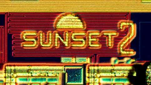
Chip Graffiti: Hilarious Arts of Integrated Circuits
01/18/2022 at 06:46 • 0 commentsWhat is Chip Art?
chip art Also known as silicon art chip graffiti or silicon graffiti refers to tiny works of art embedded in integrated circuits (also called a chip or IC).
Since IC is printed with lithography instead of building parts one at a time and there is no extra cost to add features to additional space within the chips. One of the reasons why designers started employing chip art is to discover the possibility that a manufacturer or designer copied their work.
![]()
Before the passage of the Chip Protection Act in the United States in 1984, several companies were using the term "graffiti" to prevent counterfeit chips. However, often they would also carry "contraband". Designers can create all sorts of artworks on chips, ranging from the basic initials of the designer to complicated designs. Because of the tiny dimensions of the chip the numbers are not visible without an optical microscope.
In the same period, the design cycle of products began to be cut in half and the digital design automation tools began to become more efficient, and funky designs that had previously been deemed acceptable were taken down. Also, consider the possibility that some graffiti damaged the chip on the embossed designs. Because of these changes, today's chip graffiti creators are testing the authority of technology and authority by tagging their chips with tiny Mona Lisa.
Chip graffitis is often described as an implementation of an egg that is software-based.
These Chip Graffiti are Interesting as Heck!
These records were examined through microscopes at the Strong Magnetic Field Laboratory at the University of Florida, led by Professor Michael Wesley Davidson (Microscopes, who gather all sorts of chips. They use microscopes to study the mysterious symbols that appear on them as if decoding the codes.
With the silicon graphics, MIPS microprocessor experts discovered that two Egyptian gods appeared to be focused on the mask of the chip that protects.
![]()
The silicon entice was discovered in the dark corner of Hewlett-Packard's FISO (FIFO) memory chip that is used in digital oscilloscopes.
The unidentified engineer who designed the graffiti also gave her the name "Fi-Fi", and the website has added "la femme" (in our perception, she appears like the figure of a woman)
![]()
Godzilla, the mythical creature first introduced as a character in Japanese film in the year 1954 was found hidden on a tiny cushion within the Silicon Graphics MIPS R10000 microprocessor's circuit.
![]()
This exclusive model of Mickey Mouse was found on the Mostek 5017 clock chip with hands pointing at the 12th and seventh (creating an in-built fixed-time miniature silicon clock)
![]()
A chip designer has told us that miniature versions that are a miniature version of Tux, Linux penguins, are embedded into pad rings of unknown kinds and the functions of integrated circuits.
![]()
This beautiful rendition of Thor Thor, the Nordic god Thor was discovered in the Hewlett-Packard graphics chip.
![]()
The space shuttle was located inside Texas Instruments' Schottky digital bipolar integrated circuit.
![]()
This shark is in the sea on ADI's 21061 SHARC floating-point Digital Signal Processing IC.
![]()
The Pepsi logo was created on the integrated circuit which is part of the Hewlett-Packard CPU. It's probably the smallest advertising logo that has been created to date.
![]()
This is a magnified high-power view of hummingbirds that have been etched onto HP PA-RISC7000 microprocessor wafers. The inscription on the bird says: "this bird is for you".
![]()
It's the Bugs Bunny that was found within the Cambridge Silicon Radio BC417143BQN chip and was regarded as the most loved rabbit on the planet. It is also the most compact rabbit on the planet.
![]()
The chips within Digital Equipment's MicroVax 3000 and 6200 minicomputers transmit messages from the Russian Cyrillic alphabet, a message to technicians from the other end of the Cold War who may try to reverse the engineering of VAX designs...
Read more -
Fire at ASML Plant Could Worsen the Chip Shortage
01/05/2022 at 03:38 • 0 commentsOn the third US Eastern time, Reuters disclosed that a fire erupted in a facility located in Berlin, Germany, owned by Dutch lithography giant AMSL.
![]()
Photolithography Machine Used to Manufacture Semiconductor Chips
It is a recognized fact that ASML is a provider of production equipment that is used by the top semiconductor chip makers within the industry. With the global shortages of semiconductors over the last two years, major chipmakers are planning to increase capacity. this "responsible" semiconductor manufacturer is increasing the production process of equipment for semiconductors.
ASML stated that the place that was the scene of the fire was once part of Berliner Glas, a supplier of ASML. Berliner Glas was acquired by ASML in the year 2020 when the company was generating annual revenues of 220 million euros.
ASML stated that it would be able to calculate the losses over the coming days, and the final results will be released once the data was compiled.In the report by Bloomberg Technology, the ASML shut down the affected section of the plant, while other parts of the facility were still operating. Additionally, analysts are concerned that the incident could further aggravate the worldwide shortage of chips that has led to an increase in demand for semiconductors.
ASML shares increased by 1 percent prior to the announcement and then closed down 0.7 percent to 701.70 euros on Monday.
If anyone has any problem or claim with the images featured on this site, please get in touch with us.
-
MICLEDI Demonstrates New MicroLED Arrays Based on a 300mm CMOS Platform
12/20/2021 at 04:03 • 0 commentsMICLEDI Microdisplays is an innovative technology company developing microLED displays that are designed to take advantage of the latest Gen. AR Glasses Technology The company has presented the first array of microLEDs designed for AR built on a 300mm CMOS manufacturing platform.
MicroLED is a cutting-edge technological advancement in the screen that claims bright and high contrast while decreasing power consumption. (AR) and virtual reality (VR) applications that give the most immersive experience for the user.
- CMOS-fab-compatible RGB epitaxial material that has been reconstructed onto 300mm CMOS wafers which are integrated into the latest CMOS backplane ASICs using hybrid bonding W2W.
- Pixel-level Fresnel beam shape of the lens to ensure High-Efficiency Waveguide integration.
- MicroLED technology is specifically developed for industry-standard tooling and manufacturing processes that are utilized to produce large quantities within CMOS foundries.

(Enclosed microLED dies with test arrays) AR headsets are currently heavy and heavy. Every major tech company spends money on AR to influence the future of its consumer products. According to a research company Yole Development, the demand for displays that incorporate microdisplays into AR headsets is anticipated to rise at a rate higher than 100%, growing to $1.8B by 2025, and over $4.9B in 2027.
About MICLEDI
MICLEDI Microdisplays is a fabless manufacturer of microLED displays aimed towards those who are in the Augmented Reality (AR) market. MicroLEDI's technology is built on an ingenious blend of III/V processing of materials, 3-D integration, as well as 300mm CMOS ASIC Backplane technology which is joined wafer-to-wafer to create an independent small monolithic AR display that has the excellent image quality and high energy efficiency. MIC LED is supported by Flanders Innovation and Entrepreneurship (VLAIO).
-
COSEL Launches the New 300W PJMA Power Supply
12/18/2021 at 03:35 • 0 commentsCOSEL Co, Ltd (6905: Tokyo) today announced the expansion of its medical power offerings by adding 300W power of COSEL Co, Ltd's PJMA series.
Features:
- I/O isolation: 4kV
Extra-wide temperature of operation that is : -20degC to 70degC
The input for universal use is 85V264V AC
- It supports applications that use BF (Body Floating) applications
- Low power consumption there is no load
![]()
If you require an efficient power supply, the latest PJMA offers a very high cost-to-quality proportion due to its solid platform design. The PJMA can be adjusted by the built-in potentiometer output voltage can be found in four levels (12 24, 36 as well as 48 VDC).
For protection techniques, the PJMA series is enhanced with inrush current limiting, overcurrent/overvoltage, and thermal protection. In terms of EMC testing, devices from the family comply with the EN55032-B, EN55011B, CISPR32B FCC-B, CISPR11-B, and the VCCI-B. Additionally, an additional EMI filter COSEL type NAC could be used for devices required to have lower emission levels.
It is a part of the PJMA series is enclosed in a galvanized steel case with a fan behind the box to increase its strength and long-lasting. The PJMA300F is a weight limit that is 1.0 kg and dimensions of 102 x 41 x 193mm [4.02 x 1.61 7.48 inches]. 7.48 inches[4.02 x 1.61 x 7.48 inches] (W by H by D).
The PJMA series has a five-year warranty as well as being RoHS, REACH as well as Low Voltage Directive conforming.
With the introduction of the PJMA300F model, it has expanded the PJMA series now has models with a range of 300W up all the way to 1,000W (PJMA1000F) and also 600W models (PJMA600F).
About Cosel
Cosel Co Ltd has been an important global manufacturer of switch-mode power supplies and EMF filters since 1969. Cosel produces and produces tiny high-efficiency DC/DC and AC/DC devices for medical and ITE applications that utilize the latest technology and designs. AC/DC products vary from 3W to 10KW for board-level, open frame, DIN Rail, Modular and enclosed versions. With power levels that range in the range of 1.5W and up, the DC/DC units are available in board-level as well as DIN rail mount models. EMI Filters come in a variety of sizes, from 3A to 600A, with photovoltaic-specific variants available. Many EMI Filters can also be installed on the DIN rail. Cosel's immediate field support and exceptional engineering support assist our customers."
-
ST MEMS ScanAR Tehcnology Boosts AR Glasses Development
12/15/2021 at 03:26 • 0 commentsIn November 2020 ST entered into a partnership agreement with Quanta to design a prototype of AR intelligent glasses. To further improve the technology, ST launched an initiative dubbed"the IEEE Laser Scanning Augmented Reality Alliance in March 2021. Rajagopalan is the chairperson of LaSAR Chairman of LaSAR. Both companies share information regarding laser scanning technology and collaborate on the design of equipment components, methods, and techniques.
LaSAR is the most recent initiative by IEEE Industry Standards and Technology Organization (IEEE-ISTO) which provides its clients legal and financial infrastructure as well as help in the management of standards development and the commercialization of new technologies.
![]()
ST has announced a new range of products called MEMS ScanAR, which was specifically designed to be used for Augmented Reality applications, focusing on improving performance while cutting down on weight, size, and power consumption. MEMS ScanAR is a product line of ST. MEMS ScanAR family includes MEMS micromirrors as well electronic components that regulate the mirrors, as well as laser diodes.
To aid in the integration process, ST developed a complete reference design based on MEMS ScanAR components. It is designed to be focused on the application and includes essential tools to aid in the development and use of intelligent glasses. The design of the reference platform is adaptable to meet the requirements and expertise of all our clients.
As opposed to the bulky AR glasses that were used in the past tiny lightweight and efficient AR glasses are more suitable for use in all conditions. As the largest manufacturer of the world's consumer MEMS applications, STMicroelectronics has shipped over 20 billion items, and ST is the largest MEMS micromirror maker in the world. Its micromirror is the core is the heart of AR glasses and the image projected onto the lens needs to be realized by the vibrating process that takes place inside the micromirror. At the present, ST has three different MEMS micromirror technologies, which include static micromirror and electromagnetic micromirror, and piezoelectric micromirror. In all three, the micromirrors made of piezoelectric micromirror have the highest importance. vital one, and it is the most sophisticated MEMS micromirror technology that permits optimizing the power consumption and dimensions of optical devices. There are several laser tube drivers, as well as micromirror drivers that make up an integrated into the optical system. To achieve compact dimensions and low power consumption, the device must be connected to the piezoelectric MEMS micromirror technology.
LBS is not any new technology, rather it's an established technology that is being tested in the market. For example, Microsoft, North, and Intel are all using LBS technology. LBS is also used inside the lidar technology in automobiles. In the case of equipment designed for end-users, the most current application is the look for medical equipment to treat veins that are found in the arms of patients. ST launched the first miniature projector it had in the year 2012 that utilized ST laser beam scanning technology. Since 2012, the ST's LBS technology has been employed across a range of sectors which includes Intel notebook Realsense devices and one of the first smart glasses created in collaboration with North. DavideBRUNO believes that 2025 will be the one that will decide the general use of AR glasses. Beyond the realm of AR and 3D-sensing, use to LBS in the area of automobile lidar (LiDar) along with industrial applications is also a major market for the application.
Furthermore, LBS uses a laser light source, so the brightness is very high. Concerning power consumption, it's LBS which uses a single-line display buffer upgrade, while other competitors utilize the whole...
Read more -
What's the Difference between Microprocessors and Microcontrollers?
12/13/2021 at 03:41 • 0 commentsIntro
The microprocessor, as well as microcontrollers, can be two frequently employed terms in electronics. What are they? What is the difference between them?
A microprocessor (MPU) can be described as an integrated circuit that executes the fundamental arithmetic and operational, and logical functions of computers. It includes the Arithmetic Logic Unit (ALU) which processes the data, as well as a Control Unit (CU), which controls the activities that are performed by the ALU.
The microcontroller (MCU) can be described as one type of microprocessor which also has memory and input/output (I/O) ports as well as other functions needed to regulate devices like motors or actuators.
Both have advantages and drawbacks, however in general microcontrollers are better suited to controlling devices (such as washing machines MP3, Arduino interface, etc.) in contrast, microprocessors are more suited to general-purpose computing (e.g. personal computers).
The key difference between the Microcontroller and the Microprocessor Microprocessor
The primary distinction between the microprocessor and microcontroller is that the microprocessor is designed to function as general-purpose, whereas the microcontroller is equipped with the necessary peripheral components as well as an I/O port to allow it to be able to do specific tasks.
A microprocessor may also include additional peripheral components that are added to it in the course of manufacturing they are known as "peripherals" or "punts". A typical microprocessor could comprise a central processing unit (CPU) and memory controllers, a graphics processing unit as well as many I/O (I/O) ports.
A microcontroller is, in contrast, is designed to contain all the necessary features to accomplish a particular task like controlling the speed of a motor or reading information from sensors. A microcontroller includes the CPU as well as memory and I/O ports in the chip. To program the microprocessor you must include external computer peripherals in the order it can communicate with sensors and other equipment.
![]()
Pros & Cons of Microcontrollers and Microprocessors
Advantages of Microcontrollers
1. Small size and affordable: Microcontrollers are generally less bulky than microprocessors and can be manufactured at a lower cost. This makes them an excellent option for any project which requires a small and low-cost controller.
2. Low power consumption: Because microcontrollers can be designed to run on very little power, they are designed for battery-operated devices such as watches or remote controls. In addition, for space-sensitive projects that require low power, an MCU is typically a better choice since it doesn't necessarily need an external power source which can take up more space.
3. Flexible: Microcontrollers can be programmed to control every electrical device - from small appliances to large industrial machines. The same chip can take the inputs of multiple sensors and carry out various tasks based on the inputs.
4. Packaging that is smaller: Microcontrollers can be packaged in a compact size, which makes them suitable for applications in which weight and size are crucial aspects.
Disadvantages of Microcontrollers
1. Limits in processing power: Microcontrollers are designed for specific functions, therefore they typically don't have the processing capabilities of microprocessors. They're not suitable in applications that require more complicated calculations.
2. Not upgradeable: The majority of microcontrollers are designed at the manufacturing facility and can't be changed afterward. This means they are not suitable for applications that might require changes or updates made to the application.
3. Insufficient input and output ports: Microcontrollers are limited in the number of output and input pins. This can be a challenge for...
Read more -
What's to Expect about the 4680 Batteries
12/09/2021 at 02:22 • 0 commentsIn the age that electrification is undergoing, changes that occur in the lithium battery market will be exponentially increased. Since the introduction of the 4680 battery, the plates associated with the battery have become uneasy.
According to CleanTechnica estimates that global sales of electric vehicles will hit 7 million by 2021. Mainland China, Japan, and the United States are the three major markets for electric vehicles. To help encourage the development of this industry and to encourage the growth of electric vehicles, the governments from China, Japan, and the United States, and Japan have repeatedly introduced policies pertaining the electric vehicle. For instance, it is, for example, the Government of the United States has introduced an "enhanced version" subsidy program to encourage buying electric cars. In addition, the Japanese administration has announced that it plans to invest around 100 billion dollars ($877 million) in a subsidy program to fund the development of modern battery factories for electric vehicles.
In the wake of the favorable policies, battery manufacturers in Japan have increased their efforts to the layout. Recently, news of Panasonic is working on the manufacturing line for Tesla's next Generation cylindrical batteries 4680 attracted the interest of those who work in the industry. 4680 battery.
![]()
The Energy Boost was triggered by 4680
Because of charging issues, Electric vehicles are engulfed in battery life anxiety that will soon turn into the basis of a "battery rivalry". Tesla placed bets on differentiating from"4680" the "4680" newly developed battery. The battery, as the name suggests is a 46 millimeter wide and an 80-mm long cylindrical battery that utilizes tabless technology to enhance security through the "all-tab" connector.
In theory, cylindrical batteries could be made larger and the individual batteries can have a higher capacity (4680 batteries are around 5.5 times bigger than 2170 cells). But, the battery may not be a huge capacity in the first place and also takes into account the difficulties of production, quick charging speed, and heat dissipation among other factors, but if the whole chassis is good for batteries, and Tesla's latest option is the dimension of 46mm.
In Tesla's standard scheme, the 21700 typically comprises four modules, including two large modules and two smaller modules. The battery of the 21700 weighs around 312 kilograms and has more than 4400 batteries.
The 4680 has over 900 batteries that are arranged in a single module. The total capacity of this structure weighs just 12kg. >span class="wordai-block" >span class="wordai-block">Its weight is 474kg for 21700 and just 438kg for 4680. 21700pack is 170whip kg . 21700pack 4680 is 215wh/kg.
Based on the findings of the research according to the results of the investigation, in this particular version of 4680 cells, the positive material is the 811 ternary high nickel system, while that of the electrode on the negative is made of graphite (with the development of further advancement, it can be converted into negative electrodes made of silicon).
The operating voltage of it will be 2.8V Mel 4.2V and the planned fast charging time is 20 minutes up to 80percent and the weight of the cell is 355g and the lifetime of 1ram 3C could reach 1500 degrees (80 percent retention of capacity).
With these design specifications, a 4680-cell battery built on CTC can produce 95-kilowatt hours which is equivalent to 21700-kilowatts in capacity. the battery pack increases by around 15 percent.
Tesla's "Tabless" Technology
As the name suggests an electrode lug is the negative and positive batteries' electrodes. It is the conductor of the metal which connects the electrodes that are positive and negative out of the cell and serves as the point of contact with the battery and the circuit...
Read more -
How to Install a Capacitor to an Amp
12/07/2021 at 08:33 • 0 commentsBasics
The purpose of the Power Capacitor
Capacitors are used as storage for electric voltage or power. >span class="wordai-block">Additionally, they serve as a reliable method to perform the decoupling task that is intended to lower the noise level of the power supply. This is why they are commonly used in audio equipment or other accessories, like an amplifier.
- Why use capacitors in Amp Circuits?
Within an amp circuit diagram, it is evident that a power cap serves the role of power storage in general similar to what it plays in another circuit. It is superior to lead-acid batteries due to its low resistance inside that allows them to recharge and provide energy at a fast speed. If you have a car audio system that is thought to have power-hungry components it is expected to generate a substantial amount of demand for current is expected and if you're an avid heavy metal or hard rock music lover, instruments such as bass and drums could increase the typical demand at a moment's notice.
- When to replace the Capacitor in Amp Circuits
Insofar as a capacitor for power capacitor is in question, it's rarely the case that there is a problem with a certified capacitor. It is only the electrolytic capacitorsthat can be damaged as time passes.
It takes more than 10 years to develop, and that's much longer than what most people are likely to own an amp. According to some audiophiles that a power capacitor isn't important. They prefer the massive three upgrade that involves the cycle battery and amp.
![]()
How do you connect an Amp to a Capacitor?
Let's use the car audio system as an example of exactly how to connect the capacitor into an amp.
Materials and Tools You will require
*Capacitor(s)
Easybom Easybomwould recommend a resistor of 1 watt during the charging process of the capacitor. A lower-watt resistor could be too hot to handle. It is also possible to use an experiment light bulb, an old-fashioned method.
*Wire
Make sure you use the same size of the circuit the capacitor is meant to be placed on.
*Wire stripping tool
*Adhesive eyelet connectors with heat shrink
Heat shrink connector butt and terminals
*Wrenches
*Memory saver
Step-by-Step Instructions
1. The capacitor must be discharged which is to be used. Place your car in a dry and quiet location where you will not be interrupted by other drivers. Connect the ground terminal of the battery.
Step 2: Disconnect the fuse and replace it with an appropriate resistor. Set up the memory save. Follow your instructions from the manufacturer for the device.
Step 3: Unplug the battery cable to its negative end.
Step 4: Determine which power supply circuit you are in. This is where you'll be able to replace or place the capacitor.
Step 5: Use the wire stripping tool for cutting the positive feed wire for the circuit, and then trim the insulation on both ends of the wire that you just cut.
Step 6: Attach an eyelet to one of the wire ends.
Step 7: Connect the feeding wire on the positive terminal of the capacitor that powers it.
Step 8: Position the capacitor as possible as the amp to lessen the noise. This is in addition to following the instructions provided by the manufacturer.
Step 9: Connect the remaining section of wire following the following diagram Make sure to use a wrench to tighten each terminal nut.
![]()
Step 10: Ground the wire, then attach the negative battery cable.
Step 11: Remove your memory saver.
Step 12: Turn on your vehicle and the capacitor will be charged, and you will be ready to go.
Summary
It is important to remove the capacitor before performing any other actions. In addition, consult an experienced mechanic if not certain of the cause.
-
Features, Instructions and more about Switching Regulator LM2576
12/06/2021 at 03:37 • 0 commentsGeneral Description
The regulators of the LM2576 series are monolithic integrated circuits that perform all active operations. A step-down (buck) switching regulator capable of driving a 3A load with good line and load control is available in several versions. Fixed output voltages of 3.3V, 5V, 12V, and 15V, as well as an adjustable output version, are offered.
These regulators are easy to operate and incorporate internal frequency correction and a fixed-frequency oscillator, requiring only a few external components.
![LM2576 VARIATIONS]()
LM2576T-5.0 Series Features
• Only 4 external components are required.
• Capable of TTL shutdown and low-power standby mode.
• High efficiency and stability.
• Thermal and overcurrent protection.
• Built-in oscillator with a fixed frequency of 52 kHz.
• P+ product enhancement tested.
Instructions
Applications of LM2576 Series
As a high-efficiency switching regulator, the LM2576 series devices are useful for a simple step-down regulator, on-card switching regulator, positive to the negative converter, and more.
How to Use LM2576T-5.0
A buck-boost setup is shown in the diagram to create a negative 12V output from a positive input voltage. This design bootstraps the regulator's ground wire to the negative output voltage then detects the inverted output voltage and regulates it to 12V by grounding the feedback pin. The highest attainable output current in this setup is roughly 700 mA when the input voltage is 12V or higher. The minimum input voltage required reduces to around 4.7V for lesser loads.
Because the switch currents in this buck-boost design are greater than in a regular buck-mode design, the available output current is reduced. In addition, the buck-boost converter's start-up input current is larger than that of a typical buck-mode regulator, which may overload an input power supply with a current limit of less than 5A.

In addition, the absolute total of the input and output voltages appears across the regulator as the maximum voltage. The highest input voltage for the LM2576 for a 12V output is +28V or +48V for the LM2576HV.
Switchers Made Simple (version 3.0) is a design program that may be used to test the viability of regulator designs with various topologies, input-output parameters, components, and so on.
User Guidelines
The regulator input pin must be bypassed with at least a 100 F electrolytic capacitor to ensure stability. The leads of the capacitor must be kept short and close to the regulator.
The input capacitor value may need to be increased if the operating temperature range covers temperatures below 25°C. With decreasing temperatures and age, the capacitance value falls and the ESR increases in most electrolytic capacitors. At low temperatures, paralleling a ceramic or solid tantalum capacitor improves the regulator's stability. For maximum capacitor working lifespan the RMS ripple, current rating of the capacitor should be more than
![LM2576 GUIDELINES]()
An output capacitor is necessary for loop stability and to filter the output voltage. Short pc board traces should be used to connect the capacitor to the LM2576. Standard aluminum electrolytic is normally sufficient, but for low output ripple voltage and good stability, low ESR versions are suggested. The ESR of a capacitor is determined by several elements, including the value, voltage rating, physical size, and construction type. Electrolytic capacitors with a low value or low voltage (less than 12V) generally have a greater ESR.
Several regular electrolytic capacitors can be paralleled or a higher-grade capacitor can be used to minimize the output ripple voltage even further. "High-frequency," "low-inductance," and "low-ESR" are terms used to describe these capacitors. The output ripple will be reduced to 10 or 20 millivolts. When running in continuous mode, however, lowering the ESR below 0.03 might cause the regulator to become unstable....
Read more -
Wearable devices: Transforming from Consumer-Grade to Professional Medical Use
11/25/2021 at 04:00 • 0 commentsAccording to data released by market research firm IDC, the global wearable device market shipped 114.2 million units in the second quarter of 2021. At the same time, IDC predicts that global shipments of wearable devices will grow from 450 million in 2020 to nearly 800m in 2025.
Among them, smartwatches and earwear devices / smart headphones account for nearly 80% of the total shipments of wearable devices. With the increasing enrichment of its application functions, in addition to realizing the basic functions such as payment, call / Wechat Synchronize, health monitoring has gradually become a new development direction of smartwatch and smart headphones.

Blood Pressure and Blood Sugar Become new Vents
The core of wearable devices is miniaturization and integration, which is an important reason why smartwatches with multiple functions and strong life attributes can be popularized rapidly. Second, compared with more professional and accurate portable medical devices, the appearance of smartwatches is undoubtedly more suitable for daily long-term wear.
At present, blood pressure monitoring has not yet formed a large-scale and daily application on smartwatches/bracelets or other wearable terminals. The portable blood pressure monitoring devices on the market are mainly divided into four categories according to technology devices that only use mobile phone cameras, pure optical sensors, optical and other sensor fusion devices, and indirect data devices. These methods do not measure blood pressure directly but measure blood pressure changes, and then measure the pressure waves generated by blood pressure in the artery through algorithm and data analysis, and there is no way to get the absolute value of blood pressure like cuff measurement.
Whether data can be obtained non-invasively through wearable devices is the key. For example, such as blood sugar and blood lipids, current sensors are difficult to detect in non-invasive cases, which means that wearability cannot be achieved. Manufacturers such as Apple and Huawei are expected to embed non-invasive physiological signal detection in the next generation of wearable devices to monitor blood pressure and blood sugar, which are critical to the risk of cardiovascular disease.
Challenges Remain in Wearable Medical Devices
for the full version of the article, please go here
---------- more on Easybom BLog----------
-
Upgrade of Domain Controller in Self-Driving Car Industry
11/24/2021 at 05:41 • 0 commentsBenefiting from the development of intelligent vehicles and the trend of automotive electronic and electrical architecture from distributed to centralized, the domain controller market is growing rapidly.
It is predicted that in 2025, shipments of autopilot domain controllers will exceed 4 million sets, and shipments of smart cockpit domain controllers will exceed 5 million sets, with a compound growth rate of more than 50%.
As the "brain" of intelligent cars in the future, the function of the domain controller is realized by the cooperation of the main control chip, system software (operating system, middleware), and application algorithm.
From the current practice of automobile companies, the high-performance hardware represented by the main control chip will be the first to get on the car, while the operating system and application software will be continuously updated with the continuous iteration of the algorithm model, gradually releasing the utilization of embedded hardware, to realize the software definition of the car.
Because of this, the field of domain controller master chip has become a popular track, and many manufacturers have laid it out one after another.

Domain Controller Chips Emerge Endlessly
At present, a large number of players have gathered in the field of domain controller master chips, especially in the field of autopilot domain controllers, including overseas manufacturers such as Nvidia, Qualcomm, NXP, Mobileye, TI, as well as domestic manufacturers such as Huawei, Horizon, Black Sesame, Core engine Technology and so on.
Among the many manufacturers, the layout of Nvidia is earlier. In 2019, Nvidia released intelligent driving SoC Orin and Orin-based computing platform Drive AGX Orin. Then, after two years of evolution and polishing, the company launched OrinX SoC. NXP has also accumulated strength in the field of domain controller chips earlier. As early as 2017, it was reported that more than half of TOP15 companies have adopted the NXP S32 platform (a fully scalable automotive computing architecture) in their upcoming models. In 2020, NXP launched the S32G domain controller chip.
TI launched a series of TDA4 chips. It is reported that the TDA4 chip supports deep learning and real-time image processing, 5-20W power consumption and performance efficiency can perform high-performance ADAS operations without active cooling, targeted integrated SoC with a general software platform can reduce system complexity and development costs, and a single chip supports access to 4-6 3 million-pixel cameras to improve vehicle perception and look processing capabilities.
Heterogeneous Multi-Core, High Integration, Low Power Consumption
First of all, the main control chip of the domain controller is moving towards heterogeneous multi-core SoC. Domestic and foreign chip manufacturers are scrambling to launch SoC chips with more powerful computing power, and the computing power has risen from dozens of TOPS to hundreds of TOPS or even thousands of TOPS.
The core of the ECU era is the MCU chip. In the era of the domain controller, the intelligence degree of automobiles increases greatly, and the complexity of operation increases exponentially. In the process of intelligent function development, high-performance hardware is often embedded in advance, and the function is updated through algorithm software, which requires the main control chip of the domain controller to have a stronger core and more powerful computing power.
Different from the MCU chip based on CPU, the SoC chip integrates many modules such as CPU, AI chip (GPU/FPGA/ASIC), deep learning acceleration unit (NPU), and so on. The computing power of the SoC chips mainly comes from AI chips.
Among them, GPU, which is mainly based on image computing, has significantly more computing units than CPU, which helps SoC chips to gain stronger computing advantages than...
Read more -
What is an Electrolytic Capacitor
11/20/2021 at 04:25 • 0 commentsBasics
- How Electrolytic Capacitors are Made

The figure above is the internal structure diagram of a commonly used electrolytic capacitor. Most electrolytic capacitors (also known as e-caps) are polarized capacitors that are mainly formed of two thin layers of metal foil and paper spacer filled with electrolyte. A dielectric oxide layer acts as a dielectric medium - electrical insulation amid anode and cathode foil.
- Electrolytic Capacitors Symbol

The most common symbol for an electrolytic capacitor (polarized capacitor). The left diagram is by IEC standard (Europe) while the right one is by ANSI standard (the US).
- Why Choose Electrolytic Capacitors
An electrolytic capacitor can adapt to higher frequency circuits than a usual ceramic capacitor can do because of its high capacitance values. Besides, they do a better job than super-capacitors in handling ripple current. And they are built to low volume which saves lots of space on a board, saving direct cost.
Types & Applications
The electrolytic capacitor is a big family and has developed for nearly a century as a classic passive electronic component. Among the wide spectrum of e-cap, there are 3 kinds of them widely used in industry practice. They vary from each other in size, capacitance, and applications.

Aluminum, Tantalum and Niobium Electrolytic Capacitor
- Aluminum Electrolytic Capacitor
This kind of electrolytic capacitor has passed the longest period of design and manufacture, from the “Wet” type to the “Dry” type. They are named from the aluminum can which rolls up the anode and cathode and can be divided into the solid type and the non-solid type.
Nowadays, aluminum capacitors are largely used in camera flashes, automotive airbags, power-factor correction, etc.
- Tantalum Electrolytic Capacitor
Tantalum capacitors are much more long-price than aluminum electrolytic capacitors. They produce low leakage with a high capacity and are often used with ceramic or film capacitors in power supply decoupling targets. Tantalum electrolytic capacitors feature a self-healing mechanism that functions to reduce MnO2 electrolytes into insulating Mn2O3. In addition, they behave superiorly stable in harsh environments (especially high-temperature ambient).
- Niobium Electrolytic Capacitor
The niobium capacitor is relatively a young competitor in the market for the tantalum capacitor. They have a thicker dielectric layer and a lower breakdown voltage than tantalum capacitors. Besides the self-healing mechanism as tantalum capacitors inherent, niobium capacitors have one more feature: self-arresting mechanism. The mechanism operates to protect the chip from short circuits fault on account of local breakdown. What's more, they excel in resisting vibrations and shocks.
Niobium electrolytic capacitors favor their use in consumer, industrial, automotive, aircraft fields, and so on.
---------- for the full version of the article, click here ---------- -
Flux Capacitor: Time Travel at Your Own Risk!
11/19/2021 at 06:10 • 0 commentsPreface
A flux capacitor is a fictional device that was created in the award-winning trilogy of films Back to the Future. It is used to power a time travel machine called a DeLorean DMC-12. Flux capacitors are capable of breaking through space-time, which enables them to do many things such as send Marty McFly back in time when he needs it or speed up the fluxing process for flux compression engines.
Somehow the movie has a great cultural effect and evokes numerous fantastic re-creations in many art segments. People put the BTTF flux capacitor element everywhere, like, on a birthday cake:

on a T-shirt:

and even on their body! (Well, I guess there's no more question of whether they're true fans or not...)

Of course, electronics hobbyists wouldn't miss the party. They MADE one by hand (at their own risk!).

(Mini 1/10 scale Flux Capacitor)
How Does a Flux Capacitor Work?
Flux Capacitor Theory
The first functional prototype of a flux capacitor was built in 1947 by Dr. Emmett Brown and his assistant, professor Albert Einstein.
According to the flux capacitor theory in this sci-fi film, it is believed to be needed for time travel to occur. In the film, it works by taking 1.21 gigawatts of electrical power from a plutonium-powered nuclear reactor and shooting it into a magnetic field which then sends it into a mercury-based core that has been activated by a laser beam from another set of electrodes at precisely 88 miles per hour. This is supposed to briefly push the DeLorean's atoms close enough together so that time travel is possible. Besides, the three sets of incandescent lamps would flicker intensively when the beam is generated.
Delorean Time Machine
Except for the flux capacitor, the DeLorean is also equipped with time circuits, Mr. Fusion, and other elements all together to satisfy the condition of time travel.
The time circuit system reads anything with a flux field. These flux fields are all over the place in the year 2015 but are generally absent in 1955 and 1985. The time circuit system works by pressing the blue button on the console, then inputting destination coordinates into the keypad, and then the time circuits will lock onto the coordinates until the DeLorean travels through time.

(Back to the Future car dashboard)
In the past. The time circuits will read anything with a flux field, so the time circuits can be fooled by something like a flux capacitor, for example. Also, the time circuits use voice commands to operate, which means that they can be triggered by a voice activation system. These two facts together mean that Marty McFly can get away with saying "1.21 Jigowatts" rather than "1.21 gigawatts".
In the future, there is a Mr. Fusion unit that powers the time machine. It uses household waste as fuel, which can be obtained by asking Mr. Fusion to "please provide output level". The DeLorean time machine has an input port for household waste and an output port that throws the garbage into the time travel device in a flash of electricity.

(Marty McFly driving the DeLorean with the Flux Capacitor behind him)
Other equipment on the DeLorean Time Machine includes a Plutonium Chamber, which provides the 1.21 gigawatts of power needed to travel through time; a Digital speedometer, which monitors the car's speed; an Electric gas gauge, which provides a readout on how much power is left in the Plutonium Chamber; an Alarm clock, which is set to 8:00 AM, the time Marty falls into the future; a Clock tower, which is used for time travel reference points—one year before the lightning strikes, one minute to midnight on the night of the lightning strikes, one year after the lightning strikes, and finally on the date of Marty's arrival into the future; and finally, a set of Time-jump plates.
To ensure that the time machine's size stays the same in 1955, 1985, and 2015, the fuel tank and the plutonium chamber have to be full before traveling through...
Read more