-
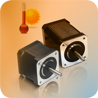
Why Do Stepper Motors Lose Steps When They Get Hot?
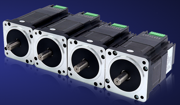
04/11/2024 at 03:06 • 0 commentsWhen a stepper motor gets hot, it loses steps and fails to rotate. Under no-load conditions, the following may be the reasons:
- Excessive load or stuck: If the motor load is too large or the motor bearings are stuck, it will cause the motor controller to continuously output current, causing the motor to overheat, and it will easily lead to loss of steps and the motor not rotating.
- Drive circuit problems: Unreasonable drive circuit design or unstable drive voltage will cause the motor to heat up and affect its normal operation.
- Poor heat dissipation of the motor shell: When working in a high temperature environment for a long time, poor heat dissipation of the motor will cause the motor temperature to be too high and easily damage the motor.
- The stepper motor generates serious heat: The stepper motor itself generates a certain amount of heat due to its working principle. However, if the motor heats up severely, there may be a problem with the motor's internal windings or iron core, which requires inspection and repair.
![]()
To solve this problem, the following measures can be taken:
- Check the load: Make sure the motor load is within the normal range to avoid overload or underload. At the same time, check whether the motor bearings are normal. If any abnormalities are found, they need to be replaced in time.
- Check the drive circuit: Make sure the drive circuit design is reasonable and the drive voltage is stable. If there is a problem with the drive circuit, it needs to be repaired or replaced in time.
- Optimize heat dissipation: Ensure that the motor casing has good heat dissipation conditions. You can install heat sinks or fans and other heat dissipation equipment on the motor casing to help the motor dissipate heat quickly.
- Check the motor: If the motor heats up severely or other abnormalities occur, the motor needs to be inspected, repaired or replaced in time.
-
Several Types of DC Stepper Motors with High Waterproof Levels
04/11/2024 at 03:03 • 0 comments1. IP65 DC stepper motor
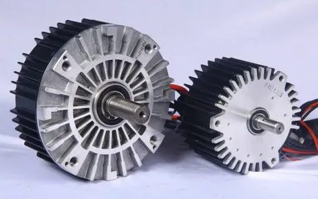
DC stepper motors with protection class IP65 have a high degree of dust and water tightness and are suitable for some special working areas, such as production halls, sewage treatment plants, etc. This type of motor has a tightly sealed housing that can prevent the ingress of dust, sand and splashing water, and has the ability to adapt to harsh environments.
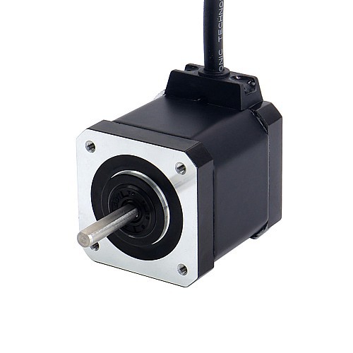
2. IP67 DC stepper motor
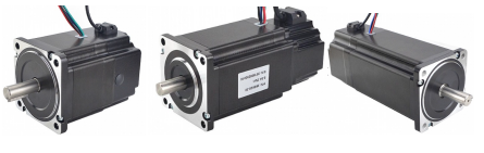
The DC stepper motor with IP67 protection has a fully enclosed structure, is waterproof, can work underwater and is dustproof. This type of motor is generally used in applications that require long-term operation in harsh environments. These include rain and snow weather, swamps, hot springs and other places.
![]()
3. IP68 DC stepper motor
The IP68 DC stepper motor is a fully enclosed, waterproof structure that can completely isolate the ingress of water molecules and will not be damaged even if immersed in water for a long time. such as underwater detection and other fields.
4. IP69K class DC stepper motor
The IP69K-rated DC stepper motor is a fully enclosed high-temperature and high-pressure structure with very high waterproof, dustproof, high-temperature resistance and corrosion resistance. Such motors are commonly used in the food and beverage processing industry, medical equipment, shower equipment and other applications where high hygiene standards are required.
In general, DC stepper motors with different waterproof levels have different characteristics and application ranges. When selecting, users should determine the required waterproof level based on the specific working environment and needs.
-
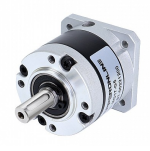
What are the components of a DC motor?
03/12/2024 at 06:48 • 0 comments1. Structure of brushless DC motor
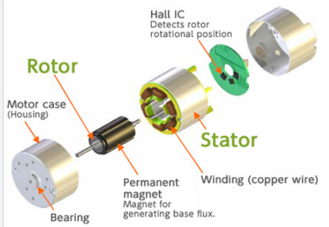
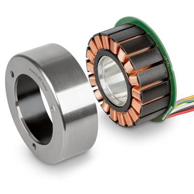
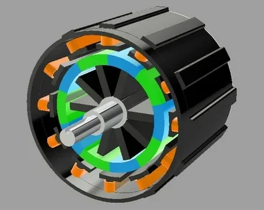
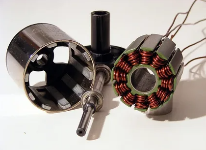
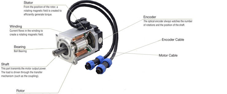
Brushless DC motors are complex mechanical system composed of multiple parts. Its main components include the motor body, rotor, stator, bearings, end covers, magnets, encoders, drivers, etc.
1.1 Motor body: The motor body is the core part of the brushless DC motor and usually consists of two parts: the rotor and the stator. The rotor can be an inner rotor or an outer rotor, which is composed of magnetic poles, shafts, bearings, etc.; the stator is the fixed part of the motor and is composed of coils, iron cores, and motor brackets.
1.2 Rotor: The rotor is the rotating part of the motor, which consists of permanent magnets, shafts and other components. The permanent magnets of the inner rotor are located inside the rotor, while the permanent magnets of the outer rotor are located outside the rotor.
1.3 Stator: The stator is the directional component of the motor. It is composed of coils and iron cores and is the immovable part of the motor.
1.4 Bearings: Bearings are the core components that support the rotating part of the motor. Rolling bearings or sliding bearings are usually used.
1.5 End cover: The end cover includes the front cover and the back cover. It is a component used to seal the motor. It is usually installed at both ends of the motor body.
1.6 Magnetic steel: Magnetic steel is a component used to generate a magnetic field in a motor. It is usually composed of permanent magnets or electromagnets.
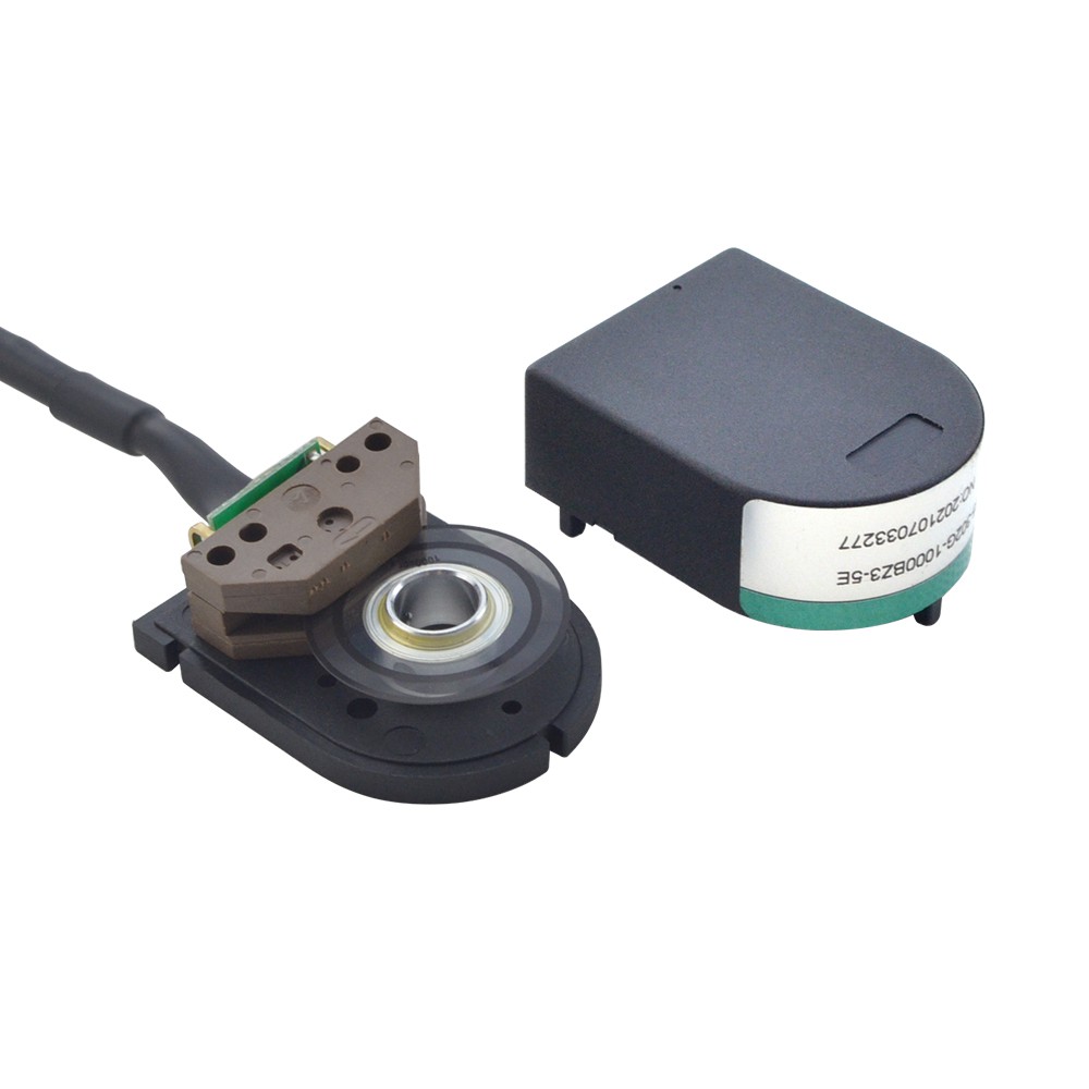
1.7 Encoder: Encoder is a component in the motor used to detect the rotor position and motion status. It usually includes photoelectric encoders, magnetic encoders and other types.
1.8 Driver: The driver is the core component of the motor control system. It can control the speed and steering of the motor based on signals.
![]()
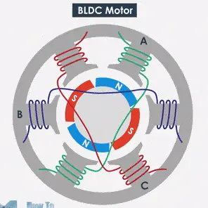
2. Working principle of brushless DC motor
The working principle of the brushless DC motor is to generate a magnetic field between the stator and rotor through permanent magnets and current, thereby generating electromagnetic torque. Specifically, when current passes through the stator winding, a magnetic field is generated in the stator, and at this time, the rotor permanent magnets are subjected to magnetic forces and start to rotate. When the rotor rotates to a certain position, the driver changes the direction of the current so that the rotor continues to rotate. By continuously changing the direction of the current, the motor can be continuously rotated.
3. Advantages of brushless DC motor
Brushless DC motors have many advantages, such as high efficiency, high torque, low energy consumption, lightweight, low noise, etc. In addition, since brushless DC motors do not require the use of carbon brushes, their lifespan is also longer. These advantages make brushless DC motors widely used in robotics, electric vehicles, medical equipment and other fields.
-
How to commutate a brushless DC motor?
03/12/2024 at 06:38 • 0 comments- Commutation principle of brushless DC motor
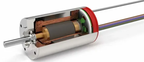
A brushless DC motors are an electric motor with multiple permanent magnets on its rotor and multiple sets of windings on its stator. The speed and direction of the motor are controlled by controlling the direction and size of the current through an electronic speed regulator. Since the brushless DC motor does not require a mechanical commutator, it can achieve the advantages of high efficiency, low noise, and long life. However, when the speed is high, the load is large, or the load changes suddenly, the reverse direction of the commutation current is required, otherwise the motor will not work properly. The commutation principle of the brushless DC motor is to use the Hall sensor or electric speed regulator inside the motor to control the direction and magnitude of the current, thereby realizing the commutation of the motor.
2. Commonly used brushless DC motor commutation methods
2.1 Hall sensor commutation
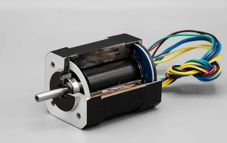
Hall sensors for brushless DC motors are divided into three types: single-axis Hall sensors, three-axis Hall sensors and linear Hall sensors. These sensors can measure the position and speed of motor rotation, thereby controlling the direction and magnitude of the current to achieve motor commutation. The specific implementation method is: when the motor moves, the Hall sensor detects the change in the magnetic field and sends the signal to the ESC control chip, which is processed in the chip and drives the power sensor to output to the motor. Make sure the coils are positioned correctly so the motor operates properly. Hall sensor commutation has the advantages of simple structure and low cost, and is suitable for low-power motors.
![]()
2.2 Electric speed regulator reversal
The electric speed regulator uses the back electromotive force principle in the DC motor to control the commutation of the motor by adjusting the direction and magnitude of the current. During reversal, the ESC control chip will automatically determine the front and rear position of the motor and the direction of the magnetic field, and control and adjust the current direction to achieve the running direction of the motor. Compared with Hall sensor commutation, electric speed regulator commutation does not require external sensors, making the design more flexible. However, electric speed regulator commutation also has some shortcomings, such as complex structure and high price.
-
Resonance of a Stepper Motor
02/18/2024 at 07:49 • 0 commentsStepper motors are known to vibrate or resonate at certain speeds, especially at low speeds. At low speeds, the motor's motion is more like a stepper, with the motor's rotor tending to oscillate back and forth between each step. This oscillation causes mechanical resonance in the motor components such as the rotor, shaft and bearings. Resonance can cause the motor to vibrate, resulting in loss of torque and precision.
For a given stepper motor, its resonance problem is difficult to eliminate, but there are some methods to reduce the vibration to a certain extent.
1. Stay away from the resonance zone
Since the motor only exists in a certain resonance area, the motor should be avoided to run near the resonance area. When the motor accelerates from a lower resonance area, it should accelerate as fast as possible, away from the resonance area, and reduce vibration.
2. Increase the subdivision of the driver
The larger the subdivision, the smaller each step of the motor will be, and the range of motion of the motor will become more delicate, so that the motor will move more smoothly, thereby reducing vibration.
3. Reduce the driving current
In the case of ensuring that the stepper motor has sufficient torque, reduce the drive current as much as possible. The smaller the current, the smaller the change in the coil current in the motor.
4. Install dampers or shock absorbers
Add a shock absorber between the motor and the mounting part, such as a rubber or silicone coupling or a tuned mass damper, which absorb the motor's vibration and reduce the resulting vibration.
If the above methods still cannot meet your vibration requirements, you need to replace a motor. You can contact the technical team of STEPPERONLINE and tell us the speed range that needs to work, and we will help you choose a motor whose resonance area is not in this speed range. -
Stepper Motor Does Not Rotate After Connecting to the Driver
02/18/2024 at 07:46 • 0 commentsFirstly, you can perform the following steps to troubleshoot the problem:
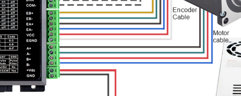
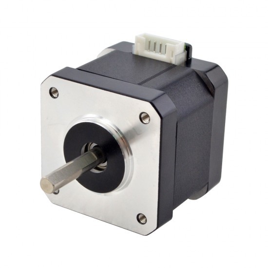
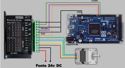
1. Double-check all the wiring. You may need to refer to the manuals of both the stepper motor and driver.
Note: It's better to test the motor and driver separately instead of installing them in your production equipment to eliminate other interfering factors.![]()
Note: The wire colors in the picture are for display only. For the actual correct wiring sequence, please refer to the motor drawing !
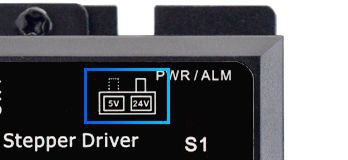
2. Check if the power voltage and signal voltage of the driver are correct. In particular, make sure the signal voltage set by the driver matches the voltage provided by the controller. According to our feedback records, 40-50% of the motors do not turn because of this reason. Because the control signal voltage is 5V, and the driver defaults to 24V.![]()
3. Try disconnecting the ENA+/- interface if you have connected it.
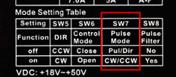
4. Power on the driver without sending any pulse signals and check whether the motor is locked. If it is a closed-loop motor, you can set the driver to open-loop mode, usually by setting SW6 to on, and then check whether the motor can run. If it can run, then there is probably a problem with the encoder part.
5. Power on the driver and send pulse signals to see if the driver gives an alarm. Record the number of alarms displayed on the driver and refer to the "Troubleshooting Table" in the driver's manual to check each potential problem. Usually, you can find the "Troubleshooting Table" in the driver's manual.
6. If you have other motors or drivers, you can perform a cross-test to determine if the problem lies with the motor or driver.
7. Check whether the pulse mode setting is correct. Some drivers can be set to the type of input pulse signal (usually SW7), so you need to select the corresponding pulse mode according to the signal type provided.![]()
-
What is the relationship between phase resistance and phase inductance and stepper motor?
01/08/2024 at 04:48 • 0 comments1. What are phase inductance and phase resistance?
Phase resistance refers to the resistance in each phase coil of a stepper motor. Inside the stepper motor, there are two or more phase coils. Each coil has a phase resistance, and its size depends on the material of the coil. , wire diameter and coil length;
Phase inductance is the static electrical parameter of the motor, which refers to the inductance of the internal winding coil of the motor. It is an important parameter that affects the torque-frequency characteristics of the motor. Generally speaking, the attenuation of the motor output torque is inversely proportional to the phase inductance (that is, the larger the phase inductance, the smaller the torque attenuation. The smaller the phase inductance, the greater the torque attenuation);
![]()
2. The impact of phase resistance and phase inductance on stepper motors;
Inductance will affect the vibration, speed and heat of the motor. Under the condition of equal resistance and guaranteed torque, the smaller the inductance, the better. In this way, the motor speed can be higher and the vibration will be smaller accordingly.
The size of the resistor mainly affects the heating and efficiency of the motor: larger phase resistance will cause the motor to generate more heat when working, because resistance losses will occur when the current passes through the resistor. This may require better cooling systems to keep motor temperatures within acceptable limits. In addition, larger phase resistance will also cause the efficiency of the motor to decrease.
3. What factors will affect the phase resistance and phase inductance of the stepper motor?
1). Coil material: The material of the coil will affect the phase resistance and phase inductance. Different materials have different electrical and magnetic conductivities, which affect the resistance and inductance of the coil.
2). Coil length and cross-sectional area: The length and cross-sectional area of the coil will also affect the phase resistance and phase inductance. Longer coils increase resistance and inductance, while larger cross-sectional areas reduce resistance and inductance.
3). Number of coil turns: The number of coil turns indicates the number of coils in the coil. More turns generally result in higher inductance values.
4). Core material and structure: The core material and structure in the stepper motor will also affect the phase resistance and phase inductance. The permeability and shape of the core affect the magnetic field distribution in the coil and thus the inductance.
5). Motor lead length: The motor outlet mainly affects resistance and has little impact on inductance. The longer the wire, the greater the resistance.![]()
4. Characteristics of motors with high inductance and low inductance/high resistance and small resistance
High inductance and large resistance motor:
Its advantage is that it can achieve the required torque by using a relatively small current, so you can choose one with a smaller current.The driver, the heating, stability and noise of the driver and motor will be much better.
Its disadvantage is that it cannot go up at high speed, and the torque decays quickly at high speed.
Low inductance and small resistance motor:Its advantages are that the driver has higher voltage and current at high speed, and its no-load starting and operating frequency are both higher.The hardness of the machine is relatively good, and the torque decays very slowly with speed.
Its disadvantages are that the current is very large, the voltage is relatively high, the heat is large, and the noise is difficult to control; the driver performance requirements are also relatively high.
Note: It does not mean that the greater the phase resistance and inductance, the greater the holding torque! Rather, under the same voltage and current conditions, the larger the inductor and resistance, the greater the driving capability.
-
How to deal with the heating problem of stepper motor?
01/08/2024 at 03:10 • 0 comments1. Causes of motor heating
For any stepper motor, it is normal to generate heat during operation, and the same is true for stepper motors. The inside of the stepper motor is composed of an iron core and a winding coil. The resistance of the operation and maintenance winding exists, and the current flowing through the motor will cause loss. The loss is proportional to the square of the resistance and the current. This is called "copper loss". In addition, there is a hysteresis eddy current effect in the iron core, which will also cause losses in the alternating magnetic field. Its size is related to material, current, frequency, and voltage. This is called "iron loss". Both copper loss and iron loss will appear in the form of heat, affecting the efficiency of the motor. Because stepper motors generally pursue positioning accuracy and torque output, they have low efficiency, large current, and high harmonic components. The alternating frequency of the current also changes with the rotation speed, so stepper motors generally generate heat.
![]()
2. Normal phenomenon of motor heating
The allowable degree of motor heating mainly depends on the internal insulation level of the motor. Only at high temperatures (above 130 degrees) will the internal insulation performance be destroyed. So as long as the internal temperature does not exceed 130 degrees, the motor will not be damaged and the surface temperature is below 90 degrees. Therefore, it is normal for the surface temperature of the stepper motor to be 70-80 degrees, which can be roughly judged with a point thermometer. This normal heating will not affect the life of the stepper motor.
![]()
3. Countermeasures for motor heating
(1) Check whether the current setting of the driver is appropriate. If the setting is too high, you can reduce the current appropriately and turn on the half-current holding function of the driver.
(2) Check whether the driver is overloaded or overheated. If necessary, add cooling measures or replace the driver with a higher power one.
(3) Check whether the stepper motor works for too long. If so, consider increasing the cooling time or using a fan for heat dissipation.
(4) Check whether the ambient temperature is too high, and increase ventilation or lower the operating temperature if necessary.
(5) Check the power cord and its connecting wires: Check the power cord and its connecting wires to make sure there is no high impedance in them, so as not to affect the flow of current and make the stepper motor hot to the touch. -
What is motor insulation made of?
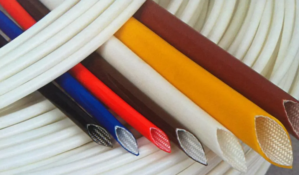
01/08/2024 at 02:04 • 0 commentsIn electrical equipment such as stepper motors, closed-loop motors, and servo motors, equipment using different insulation materials has different abilities to withstand high temperatures. Therefore, general motors have a maximum allowable temperature for their operation. Now let’s take a look at insulation materials and the temperatures they withstand.
![]()
Class A insulation materials: including impregnated cotton yarn, silk, paper and other organic fiber materials, as well as enamel on ordinary enameled wires, etc., and are currently only used on transformers. The maximum allowable operating temperature is 105°C. The temperature rise of the wire group is 60℃, and the performance reference temperature is 80℃.
Class B insulation materials: including mica, asbestos, glass fiber and other organic matter; materials and compositions made of organic paint or resin with improved heat resistance as a binder; enamel on polyester high-strength enameled wire; maximum allowable work The temperature is 130℃. The temperature rise of the wire group is 80℃, and the performance reference temperature is 100℃. It has good heat resistance, solvent resistance, adhesion performance, high mechanical strength, etc., and is suitable for small ordinary motors, electrical appliances, instruments, and telecommunications materials.
Class C insulation materials: including mica, quartz, glass, etc.; asbestos, glass fiber fabrics or their products treated with silicone resin, polyimide impregnating paint, etc. with particularly excellent thermal stability; polyimide based Enameled wire enamel, polyimide film, etc., Class C insulation grade is an insulating material with higher requirements and is being promoted and used in production. Its maximum allowable working temperature has not yet been determined, but it is probably above 180°C.
Class F insulation materials: including mica, asbestos, glass fiber and other inorganic materials, made of synthetic resin paint modified with silicone organic compounds, or alkyd, epoxy and other synthetic resins whose heat resistance meets this requirement as a binder. Material or its composition, the maximum allowable operating temperature is 155°C. The temperature rise of the wire group is 100℃, and the performance reference temperature is 120℃. Its characteristics are that it has good heat shock resistance, mechanical and electrical properties and high softening temperature. It is suitable for high temperature resistant electronics, instruments, meters and telecommunications equipment.
![]()
Class H insulation materials: Materials including silicone organic matter and inorganic materials such as mica, asbestos, glass fiber, etc., with silicone organic paint as a binder. The maximum allowable working temperature is 180°C. The temperature rise of the wire group is 125℃, and the performance reference temperature is 145℃. It is characterized by excellent friction, heat and solvent resistance. Its scope of application is general motors, transformers, four-way valves, igniters, automotive relays, etc.
Class E insulation materials: including films made of polyester resin, epoxy resin, triacetate fiber, etc., polyvinyl acetal, enamel on high-strength enameled wire, etc. The maximum allowable operating temperature is 120°C. The temperature rise of the wire group is 75℃, and the performance reference temperature is 95℃.
In addition, it should be noted that the insulation level and insulation temperature resistance are closely related, because the higher the temperature, the worse the insulation performance of the material will be. Therefore, different grades of insulation materials have a maximum allowable operating temperature, and within this temperature range, they can be used safely. If the working temperature of the insulating material exceeds its own insulation heat-resistant temperature, the insulating material will age rapidly and become unusable, which may also cause safety hazards.
-
What is the Difference between Linear Motors and Linear Actuators?
01/02/2024 at 04:50 • 0 commentsThe structural differences are:
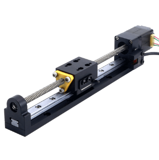
A linear motor is a mechanical device that converts rotational motion into linear motion. From the perspective of motion principles, to convert a stepper motor from rotational motion to linear motion, the simplest design is to integrate the screw nut into the stepper motor, and realize the entire linear transformation inside the motor. This method greatly simplifies the entire structural design, and in many application fields can directly use linear motors for precise linear transmission without installing external mechanical linkage devices. The basic principle is to install a nut in the center of the rotor of the linear motor, and accordingly use a screw rod to mesh with the nut. In order to move the screw rod forward and backward, some method must be used to prevent the screw rod and the rotor assembly from rotating together. Since the rotation of the screw is constrained, the screw achieves linear motion when the rotor rotates.
![]()
Linear Motor Actuators usually consist of linear guide rails, aluminum alloy profiles, supports, motors, photoelectric switches, etc. It is a transmission device that directly converts electrical energy into linear motion mechanical energy without any intermediate conversion mechanism. It has the advantages of simple structure, convenient long stroke, high acceleration, fast response and high precision. The linear actuators currently on the market can be roughly divided into two categories: synchronous belt type linear modules and ball screw linear modules. The former installs the belt on the transmission shafts on both sides of the linear module, which serves as the power input shaft. A slide block for adding equipment workpieces is fixed on the belt. When there is input, the slide block is moved by driving the belt; the latter The motor drives the screw to make the slider run. Our company is currently selling this type, but the structure is simpler. We have canceled the coupling and integrated the linear motor into the module as a whole. Please explain whether the actuators has a coupling or not.
![]()
The performance difference is:
Linear Actuators usually include the linear motor itself and its supporting control system, sensors and mechanical structure. This integrated design allows linear motor modules to be deployed faster and easier t
-
Brake stepper motor--a brief overview
01/02/2024 at 03:20 • 0 commentsWhat is a brake stepper motor?
Stepper motors are equipped with encoders, reducers, brakes and other configurations to improve the motor's application range and performance. So what is a brake stepper motor? The so-called brake stepper motor is to install a brake device, that is, a braking device, at the end of the stepper motor. When the stepper motor is powered on, the brake is also powered on, and the braking device will also break away from the stepper motor output shaft, causing the motor to normal operation. When power is removed, the brake releases tightly to hold the motor shaft. Realize the function of frequently starting and stopping a stepper motor to ensure that the motor is powered on or locked when it is powered off.
![]()
Advantages and characteristics of brake stepper motors
The stepper motor with brake is like a well-trained horse, ready for use at any time. From an industrial development perspective, the stepper motor is a great invention. It is driven by electromagnetic force and can accurately convert electrical energy into mechanical energy to achieve angular or linear displacement. Its step angle is precise, its rotation is smooth, and it responds quickly. With the pulse of current, it completes every action accurately. The addition of the brake device is the icing on the cake. It gives the stepper motor the ability to quickly lock its position when stopped, preventing accidental rotation due to external forces. This kind of locking force is powerful and reliable. No matter how the external environment changes, the stepper motor with brake can maintain its original position and remain unmoved.
Stepper motors with brakes also have many advantages such as energy saving, environmental protection, long life, and easy maintenance.
Its operation is quiet and efficient, producing almost no noise and vibration, providing great convenience for modern industrial production and daily life. In general, stepper motors with brakes are a combination of modern technology and art. It has both strong power and stable braking performance; it can accurately perform complex motion tasks and stop quickly when needed. With its unique advantages and wide range of application fields, it is leading the development of modern automation control field.
![]()
What working conditions require braking stepper motors?
For stepper motors equipped with brakes, the permanent magnet brake used has the characteristics of fast response, large holding force, and long service life. When the motor moves up and down, and when the equipment is powered off, it can maintain the torque so that the working object does not move. Will not fall off, which additionally enhances the diversification of stepper motor convenience in use.
So what are the advantages of brake stepper motors and what industries are they widely used in?
When the motor is working, it can drive the mechanism up. When the motor stops, it cannot guarantee that the platform mechanism will not fall. At this time, we need to use the brake to lock and drag the axis to position the platform height and accuracy. Currently, they are widely used in automated equipment such as dispensing machines, elevators, CNC machine tools, tapering machines, and packaging machines. Because these industries often use start-stop devices during work, they all require the use of brake stepper motors. -
What are sensed brushless motors and senseless brushless motors?
01/02/2024 at 02:56 • 0 commentsWhat are sensed brushless motors and senseless brushless motors?
1. The difference between sensored brushless motors and sensorless brushless motors
The sensor in sensorless brushless refers to "Hall sensor", so what is "Hall"? Hall refers to the Hall effect. Simply put, when a current passes through a conductor perpendicular to the external magnetic field, a potential difference will appear between the two end faces of the conductor perpendicular to the magnetic field and the direction of the current. It can be easily known through the Hall effect. Regardless of high-speed or low-speed motor operating status. It can be seen that the inductive brushless motor is a brushless motor without Hall sensor feedback. It indirectly detects the rotor position commutation through the voltage and current changes of the motor winding.
![]()
2. Characteristics of inductive brushless motors and inductive brushless motors
The position of the rotor can be known when the inductive motor is at rest, but the position of the rotor needs to be rotated for the non-inductive motor. Therefore, the non-inductive motor will shake when it just starts and stops. A brief summary is that it will shake when starting and stopping; Induction motors use Hall element sensing, which is less susceptible to interference and more accurate in judgment. Therefore, it can be applied to fast start and fast stop conditions. It usually provides better low-speed torque performance because they can accurately operate at low speeds or even at rest. Control commutation.
3. Usage scenarios of sensored brushless motors and sensorless brushless motors
When choosing between an inductive motor and a non-inductive motor, you need to consider the following aspects:
![]()
1). Speed range: If the speed is higher, it is recommended to choose a non-inductive motor; if the speed is lower, it is recommended to choose an inductive motor.
2). Control accuracy: If high-precision control is required, it is recommended to choose an inductive motor; if the control requirements are relatively low, it is recommended to choose a non-inductive motor.
3). Cost factor: If the cost requirements are low, it is recommended to choose a non-inductive motor; if the accuracy and operating stability requirements are high, it is recommended to choose an inductive motor.
4). Control distance: If the distance is less than 3 meters, you can use an inductive motor. When the distance is greater than or equal to 3 meters, it is recommended to use a non-inductive motor.
All in all, non-inductive motors are suitable for applications with small to medium power and high speed operation, such as fans, model toys, etc. Inductive motors are suitable for high-precision and high-power applications, such as machine tools, automation equipment, etc. -
How to maintain the AC servo motor control system?
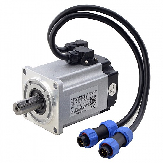
12/25/2023 at 01:09 • 0 commentsFor the maintenance of ACservo motor control systems, the following are some common precautions:
![]()
(1) Clean the servo motor and controller regularly to ensure that their surfaces are clean and to prevent dust, oil and other impurities from entering the equipment. Cleaning can be done with a soft brush or a hair dryer, but be careful not to damage electrical components.
(2) Regularly check whether the cable connection is firm to avoid looseness or poor contact. If damaged or frayed cables are found, they should be replaced promptly.
(3) According to the manufacturer's recommendations, regularly lubricate and maintain the bearings and transmission components of the servo motor. Use appropriate lubricants and follow correct lubrication methods and cycles.
(4) Ensure that the operating temperatures of the servo motor and controller are within the normal range. Avoid excessive temperatures that may cause motor overheating or controller failure. If necessary, a radiator or fan can be installed to reduce the temperature.
(5) Regularly calibrate parameters such as position, speed and torque of the servo motor to ensure its accuracy and stability. Perform appropriate calibration operations according to the manufacturer's recommendations.![]()
(6) If a fault or abnormality is found in the servo motor control system, troubleshoot it in a timely manner. You can refer to the device manual, technical support provided by the manufacturer, or professional help to solve the problem.
(7) Carry out regular maintenance work according to the manufacturer's recommendations, such as replacing parts, checking electrical connections, updating software, etc. Regular maintenance can extend the life of your equipment and maintain its performance -
How to extend the service life of servo motor?
12/25/2023 at 00:57 • 0 commentsServo motoris a common industrial motor that often appears in various fields such as automated production lines, machining centers, medical equipment, and semiconductor equipment. This kind of motor has the advantages of high precision, high speed, and high anti-interference. In order to ensure the normal operation of the servo motor and extend the service life of the servo motor, its maintenance and upkeep work is particularly important. To do this we need to do the following things.
![]()
1. Regularly check the contact and appearance of the motor cable, especially at the interface where the wire enters the servo motor, because interruptions or disconnections may occur during movement.
2. Regularly check the contact of the motor torque cable and maintain good contact. You can insist on checking once every three months.
3. Regularly check the interface between the motor and the power module and ensure that the connection is firm.
4. Check the servo motor system regularly and keep it clean. In order to prevent dust, oil, liquid and other debris from entering the inside of the motor and causing motor failure, we need to clean the air outlet and radiator of the servo motor regularly and ensure good ventilation.
5. Regularly check the indicator lights and fault codes on the servo motor control board and determine any existing faults.
6. Back up the operating program and parameters before and after the normal operation of the servo motor. Backup programs and parameters can help us quickly restore the normal operation of the motor when necessary.
7. Lubrication: Bearings, gears and other components in the servo motor require lubricating oil or grease regularly. The time interval for adding lubricating oil or grease should be determined according to the use of the motor, and should generally be done every quarter or half a year.
8. Stability: The servo motor needs to maintain stability when working. When the power supply voltage is unstable or the motor is overloaded, the motor may experience vibration or noise problems. The power supply voltage should be adjusted in time or a suitable motor should be replaced.
9. Temperature: The servo motor will generate a certain amount of heat when working. The temperature of the motor should be checked in time. If the temperature of the motor is too high, it may cause damage to the motor or unstable operation. It should be stopped in time and the fault should be eliminated.
![]()
During regular maintenance, we need to check the missing and missing parts and repair or replace them in time. If the problem part is not repaired or replaced, further damage to other parts of the motor may result.
In addition, during regular maintenance, we need to conduct a thorough cleaning of the servo motor system. The cables of the servo motor need to be moved and cleaned, usually using a pneumatic electrostatic blower for efficient cleaning.
For servo motors that have not been used for a long time, we need to clean, vacuum and inspect them before restarting them. This ensures that the motor is in optimal condition before restarting, avoiding any problems when starting to use it.
In general, routine maintenance of servo motors is the key to ensuring normal operation of the motor and extending its life. In daily maintenance, attention needs to be paid to issues such as motor cleaning, lubrication, connection inspection, stability and temperature. Regular maintenance and inspection, and timely troubleshooting can effectively protect the normal operation of the motor. At the same time, it can also appropriately extend the service life of the motor and reduce the cost of equipment maintenance and replacement.
-
Getting ready before fixing a brushless DC motor
12/20/2023 at 02:40 • 0 commentsWe'll go over a few things you should know before taking a brushless DC motor apart and fixing it here. I hope it's useful.
![]()
(1) You should dust and wipe the motor's surface to remove any dirt before attempting to disassemble it.
(2) After deciding on a good working location, tidy up the area before disassembling the motor.
(3) Understand the motor's structural features and technical maintenance requirements.
(4) Assemble the equipment and tools needed to disassemble the motor, including any specialized tools.
(5) Before disassembling the motor, if at all possible, conduct an inspection test to gain a deeper understanding of the operational flaws. In order to achieve this, load the motor for a test rotation, measure the no-load test, disconnect the load, and carefully inspect and check every component of the motor—including its temperature, sound, vibration, and other characteristics—as well as its voltage, current, and speed. Note the no-load loss and the load current.
![]()
(6) Turn off the power, unplug the motor's external wiring, and take notes.
(7) To test the motor insulation resistance, use a megohmmeter set to the proper voltage. The insulation resistance values recorded at various temperatures should be converted to the same temperature, usually 75°C, in order to compare with the insulation resistance value recorded during the most recent maintenance to ascertain the motor insulation change trend and insulation status.
(8) Evaluate the K absorption ratio. A higher absorption ratio than 1.33 suggests that moisture has never impacted the motor insulation or that the level of moisture exposure is not very high. The absorption ratio measured at any temperature must also be converted to the same temperature in order to be compared with earlier data.
-
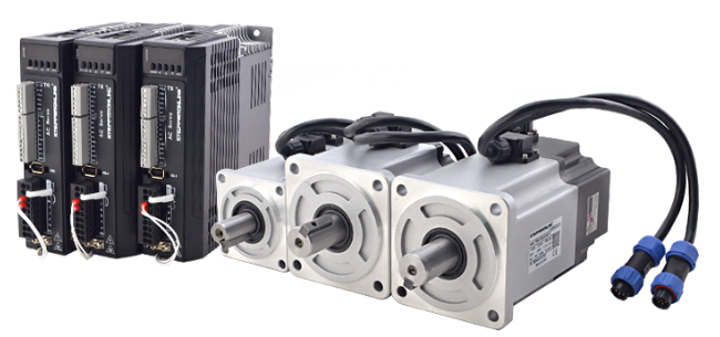
How to Solve the Jitter of T6 Servo Motor?
12/18/2023 at 01:33 • 0 commentsWhen using T6 servo motor, if jitter occurs, you can eliminate it through the following methods.
When the brake is open, the mechanical installation is balanced, the coupling does not shift, the gear meshes well, the encoder wiring is correct, and there is no interference, adjust the inertia, rigidity and other parameters of T6.
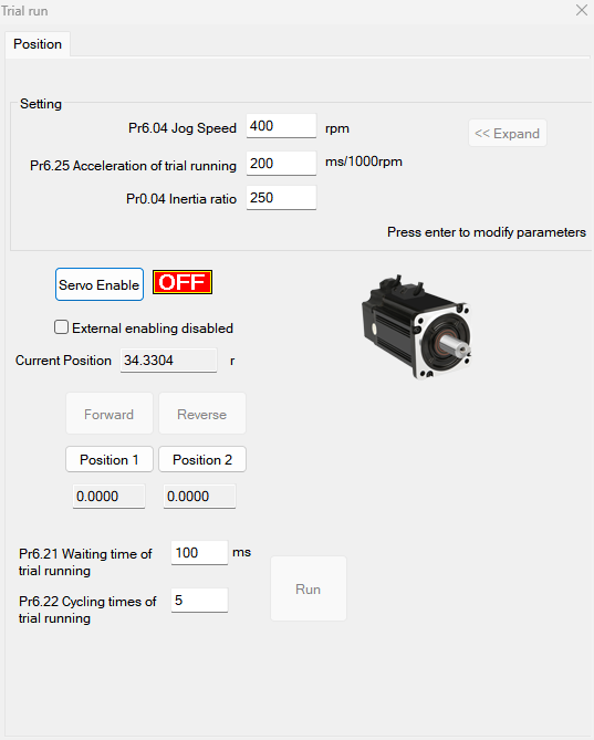
1. The wiring is correct (the motor will be automatically recognized by the driver).
2.Use the "operation test" to test whether the motor is running normally.![]()
3. Set the Pr400 value (external servo on signal Pr400=83; internal signal Pr400=3).
4. Select the control mode Pr0.01. (0: Position mode, 1: Speed mode, 2: Torque mode).
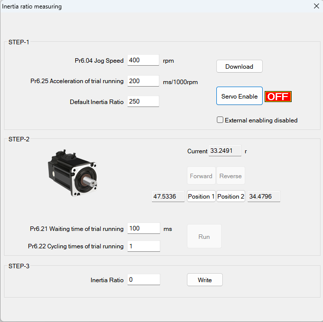
5. Connect the motor to the load and adjust the inertia ratio (Pr0.04).![]()
Before setting other parameters (such as PID settings for position loop or speed loop), it is very important to find out the inertia ratio of each axis so as to obtain the best performance. If an axis needs to be tested, connect the motor to the load.
Ensure that the axis can move within a safe distance to avoid any interference and ensure the safety and accuracy of the test. Inertia ratio identification, preconditions:
A. Servo is disabled, B. Positive limit and negative limit are invalid.
step:
a. Set the jog speed Pr6.04. The setting should not be too large (300~1000rpm is recommended), set Pr6.25 (50~100 ms/1000rpm is recommended), and set the default inertia ratio. Download these settings and select Servo Enable.
b. Click "Forward" to make the motor run in the forward direction, and click "Position 1" to save position limit 1. Click "Invert",
Make the motor run in the reverse direction and click "Position 2" to save position limit 2. Click "Run" to start inertia ratio identification.
c. After completion, click "Write" to save the inertia ratio identification results and input them into NVM.6. Connect the motor to the load and adjust the stiffness of each axis (Pr0.02, Pr0.03).
1).The motor is in stop state (servo enable is turned off). The inertia ratio needs to be set correctly, otherwise it will affect the debugging effect.
2). Set Pr0.02 (real-time automatic adjustment) = 0x01/0x11 or 0x02/0x12; then set Pr0.03 (machine rigidity setting)
(default) to set.
3). Turn on the servo enable, allowing the machine to operate according to normal conditions, and start estimating the load characteristics. associated control parameters
will be set automatically.
4). Improve the responsiveness of the motor by increasing the setting value of Pr0.03 (machine rigidity setting).
Please observe the positioning time and whether there is obvious vibration in the machine, and set the rigidity value to the maximum without vibration.
5).Save the result and write it into EEPROM.7. If necessary, adjust Pr2.22 and Pr2.23 to make the movement smoother.
8. Set the value of "pr006,007,008,009,010".
9. Adjust Pr0.00 to obtain greater stiffness.
a. Select the correct control method: Pr0.01 = 0,
b. Set Pr0.02=1 for interpolation movement,
c. Set the inertia ratio: Pr0.04,
d.Set stiffness: Pr0.03,
f.Set Pr0.00:
1) If there is no multi-axis synchronous motion, set Pr0.00 to 1 or greater than 10,
2) If multi-axis synchronous motion is required, set Pr0.00 to be the same for all axes.
3) If Pr0.00 is greater than 10, set from 100 or 150, 200, 250, ....Notice:
1. First establish the correct control method, correct specific inertia and stiffness.
2. Do not change the value of Pr0.00 when the motor is running, otherwise vibration will occur.
3. If used in manual mode, set a small value from the beginning. A smaller value means smoother operation, and a larger value means faster positioning. -
How to Solve the Problem of Stepper Motor Overheating?
12/18/2023 at 01:02 • 0 commentsCause of motor heating
For any motor icluding sevomotor spindle motor, brushless dc motor,etc,It is normal to heat up during operation, and the same is true for stepper motors.
The interior of the stepper motor is composed of an iron core and a winding coil. The resistance of the operation and maintenance winding exists, and the current flowing through the motor will cause loss.
The loss is proportional to the square of the resistance and the current, which is called "copper loss". In addition, there is a hysteresis eddy current effect in the iron core, and losses will also occur in the alternating magnetic field. Its size is related to material, current, frequency and voltage, which is called "iron loss". Both copper loss and iron loss will be expressed in the form of heat, affecting the efficiency of the motor. Because stepping motors generally pursue positioning accuracy and torque output, they have low efficiency and large current.
The harmonic component is high, and the alternating frequency of the current also changes with the speed, so the stepper motor generally generates heat.![]()
The maximum temperature the motor can withstand
The allowable degree of motor heating mainly depends on the internal insulation level of the motor. Only at high temperature (above 130 degrees), the internal insulation performance will be destroyed. So as long as the internal temperature does not exceed 130 degrees and the surface temperature is below 90 degrees, the motor will not be damaged.
Therefore, it is normal for the surface temperature of the stepper motor to be 70-80 degrees, which can be roughly judged by a spot thermometer. This normal heating will not affect the life of the stepper motor.![]()
Solutions to motor overheating
3.1 Check whether the current setting of the driver is appropriate. If the setting is too high, the current can be reduced appropriately, and at the same time, the half-current hold function of the driver is turned on.
3.2 Check whether the driver is overloaded or overheated, and if necessary, increase heat dissipation measures or replace a higher power driver.
3.3 Check whether the stepper motor has been working for too long, if so, consider increasing the cooling time or using a fan for heat dissipation.
3.4 Check whether the ambient temperature is too high, increase ventilation or lower the working temperature if necessary.
3.5 Check the power cord and its connecting wires: Check the power cord and its connecting wires to ensure that there is no high impedance in them, so as not to affect the flow of current and make the stepper motor hot. -
What are Stepper Driver ALM and BRK Ports and Wiring?
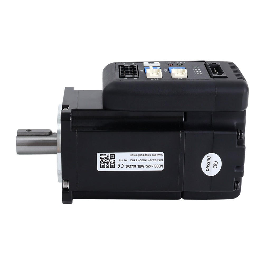
12/13/2023 at 05:33 • 0 commentsStepper drivers are very important for the normal operation of stepper motors and brushless DC motors, so in order to make the motor work better, we need to understand the stepper driver. Today, let us first take a look at the signal output ports ALM and BRK of the driver.
![]()
Please note that if you only control stepper motor operation, then you do not need to connect ALM and BRK. Because they are only used to output signals and are not used to control the motor. Here are some descriptions of these two ports:
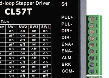
1.ALM
ALM is the alarm signal output port. When using it, it needs to be connected to the signal receiving end of the driver. There are two wiring methods for the ALM port, as shown below:![]()
When the driver sends an alarm, the internal switch between ALM+ and ALM- is closed and an alarm signal is output to the controller.
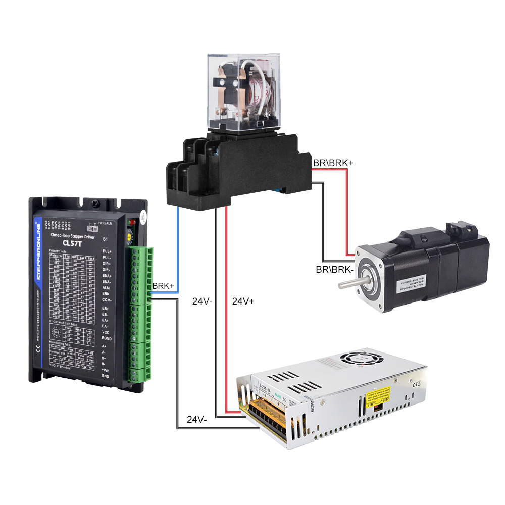
2.BRK
BRK is the brake signal output port. When using it, you need to connect the relay and the brake of the motor. The wiring method is as follows:![]()
When the driver outputs the braking signal, the relay is disconnected, the motor is braked and stops running.
Compared with a separately powered motor brake, using the drive's BRK port to control the brake for braking results in faster response. -
Servo System : A Brief Overview
12/11/2023 at 09:32 • 0 commentsWhat Servo System Means
Greek-derived ServoMechanism is the source of the acronym Servo, which means slave. As the name implies, it indicates that the system executes the intended movement by following external instructions, which may include position, speed, torque, and other variables.
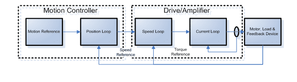
A servo system, sometimes referred to as a follow-up system or servomechanism, is a feedback control system that is used to precisely track or replicate a particular process. An automatic control system called a servo system makes it possible for the output controlled quantities, like the object's position, orientation, and state, to adapt to changes in the input target (or given value). The primary function of this device is to increase, modify, and control power in accordance with control command specifications. This allows the drive device to control torque, speed, and position in a highly convenient and adaptable manner.
![]()
Main Function
1. Use low-power command signals to control high-power loads; 2. To achieve long-distance synchronous transmission in the absence of a mechanical connection, the input shaft controls the output shaft located at a distance; 3. Allow the output mechanical displacement to precisely track electrical signals, such as those from recording and indicating instruments, etc.
The Main Structure
Three components make up the servo system: an electric motor (typically a servo motor), a power drive device, and a controller.
The power drive device functions as the main loop of the system, and the controller modifies the control amount based on the difference between the numerical control system's given value and the actual operating value detected by the feedback device. In accordance with the size of the control amount, it applies electric energy from the power grid to the motor on the one hand. Alternatively, it modifies the motor's torque. Conversely, it transforms the grid's consistent voltage and frequency power supply into the alternating current or direct current needed by the motor, depending on its specifications; the motor then operates the machinery in accordance with the amount of power.
![]()
Control Method for Servo Systems
Both closed-loop and open-loop control are possible with servo systems, however closed-loop control is more common.
Open-loop control system: This type of system control operates without the need for feedback data and does not feed back control outcomes to modify the system that is being controlled at the moment. For instance, when you flip on the light switch, the control activity ends the instant you press the switch; the activity of pressing the switch is independent of whether the light is on or off; shooting a basketball: the ball can't be controlled once it's released. The control activity ends when the ball is released, regardless of whether it is scored or not.
A closed-loop control system is one that can modify control actions in response to errors in control results and feed back control results for comparison with desired values. As an illustration: Prior to adjusting the faucet, determine the anticipated water flow rate in your mind. Once the faucet is opened, use your eyes to see how the current flow rate compares to the anticipated value. Then, continuously adjust it with your hands to create a feedback closed-loop control, just like when you ride a bicycle.Similarly, to create a closed-loop control, the direction and speed of travel are continuously adjusted.
Applications of Servo Systems
Automated production lines, industrial robots, CNC machine tools, aerospace, medical, optical, and other industries all make extensive use of servo systems. Owing to its exceptional accuracy, dependability, and efficiency, servo systems have emerged as a fundamental technology in the realm of contemporary machinery production.
-
How to Adjust the Speed of Brushless Motor?
12/04/2023 at 06:46 • 0 commentsHow to adjust the speed of brushless motor?
It is different from the speed regulation of stepper motors (the principle of speed regulation is to rotate a step angle every time a signal is received, so the speed regulation method of stepper motors is frequency speed regulation, that is, the speed of the motor is controlled by changing the frequency of the pulse signal. Adjusting the pulse signal voltage will not change the motor speed.) The brushless motor (bldc motor) has three speed adjustment methods:
1. Voltage speed regulation: Generally, a brushless motor is matched with a driver. By changing the output voltage of the driver, the input voltage of the brushless motor can be controlled to adjust the motor speed.
![]()
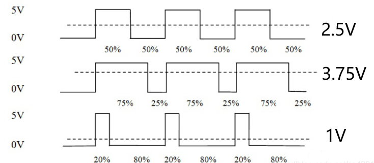
2. PWM speed regulation: PWM speed regulation uses pulse width modulation to modulate the constant DC power supply voltage into a pulse voltage sequence with a constant frequency and variable width, so that the average output voltage can be changed to adjust the motor speed. The speed can be adjusted by changing the voltage. Its essence is to adjust the duty cycle. Simply put, the duty cycle is the time ratio between high level and low level in the pulse signal. For example, assuming that the high level is 5V, the low level is 0V, and the duty cycle is 50%, that is half the high level time and half the low level time. At a certain frequency, you can get a simulated 2.5V Output voltage, then with a duty cycle of 75%, the resulting voltage is 3.75V.![]()
The larger the duty cycle, the higher the output pulse amplitude, the larger the voltage, and the higher the rotational speed. On the contrary, the rotational speed will decrease. Therefore, when using PWM speed regulation, if the high-level amplitude is 5V and the amplitude is 3.3V, the motor's speed will only be 66% of the full speed. At this time, if a higher speed is needed, the maximum speed of the motor can be increased. Corresponding ratio to achieve the required speed.
3. Series resistor speed control: A potentiometer can be connected in series, but the method is inefficient and only small-power motors can be used. It is generally not recommended to use a potentiometer to regulate the speed of high-power motors. -
How to Solve an Encoder Error in a Servo Motor?
12/04/2023 at 01:41 • 0 commentsAn essential tool for determining the motor's speed and angular displacement is the servomotor encoder. However, frequent use or other factors could cause the encoder to malfunction. This post will discuss a few typical servo motor encoder problems and offer helpful maintenance advice.
1. Encoder signal loss: This can be brought on by a malfunctioning encoder, a damaged cable, or a bad cable connection. Replacing damaged cables, inspecting and re-connecting cables, and changing the encoder are some solutions.
2. Inaccurate encoder readings: This could be brought on by a dirty, damaged, or improperly calibrated encoder. Replacing the malfunctioning encoder, performing error calibration, and inspecting and cleaning the encoder are some solutions.
3. Vibration or noise from the encoder: This could be the result of a loose, unsteady, or broken encoder. Reinstalling the encoder, tightening it up, or changing the damaged encoder are some solutions.
4. Encoder feedback error: The mismatch between the actual position and the encoder output signal could be the cause. Recalibrating the encoder, examining and modifying the encoder feedback parameters, or swapping out the malfunctioning encoder are some of the solutions.
![]()
Furthermore, encoder abnormalities can arise during normal and no load conditions when using servo motors. At this point, it will seem as though there are errors or distortions in the encoder feedback data, which is why the servo motor isn't operating correctly.
The potential causes are the following:
1. Incorrect installation: In order to guarantee a steady and efficient feedback signal, the servo motor encoder must be mounted on the motor in the proper manner. An improper installation or looseness could lead to an encoder malfunction while it's working.
2. Magnetic pole reversal: Accuracy and matching between the servo motor encoder's rotor and stator are required. The encoder will not function correctly if there is magnetic pole reversal.
3. Damage to the encoder: During operation, the servo motor encoder is a relatively delicate component that is prone to damage. The encoder won't function correctly if it is damaged.
The following are the corresponding measures:
Examine the installation: The first thing to do when a servo motor encoder anomaly arises is to make sure the encoder is installed correctly and tighten the screws at the appropriate locations.
2. Verify the matching degree: The encoder and motor's matching degrees must be verified if magnetic pole reversal takes place. They must be changed if they don't match.
3. Replace the encoder: You should think about replacing the encoder if it has been damaged. Make sure you select the right brand and model and follow the right procedures when replacing an encoder.
![]()
The following considerations must be made when fixing the servo motor encoder:
1. Safety: To avoid unintentional harm, disconnect the power supply before beginning any maintenance and adhere to all applicable safety operating procedures.
2. Maintenance manual: To find out the precise maintenance procedures and safety measures, refer to the servo motor encoder's maintenance manual.
3. Tools and supplies: Get ready the necessary screwdrivers, wrenches, cleaners, and other supplies needed for the repair.
4. Debugging and testing: To make sure the encoder resumes normal operation after the repair is finished, carry out the necessary debugging and testing.
Pay attention to maintenance: During the long-term use of the servo motor, pay attention to regular maintenance of the motor and encoder to maintain their good condition.
-
Where can we use a servo motor?
11/28/2023 at 03:32 • 0 comments1. Automated production line: Servo motors can be used to drive assembly lines, robotic arms, handling equipment, etc. and for automated product packaging/bottling and labeling, among others.
2. Logistics and transportation industry: For example, in large storage warehouses, there are many AGV vehicles used for transportation and deployment of goods, and they use servo motors for movement and steering.
3. Microelectronics production and processing: For example, the production of various types of chips requires mechanical arms driven by servo motors.
4. Robot technology: Servo motors are an indispensable part of robot technology. They are used for joint drive, arm movement, etc. of robots. They can achieve complex actions and precise motion control, giving robots higher flexibility and accuracy. .
5.
6. Camera autofocus: The high-precision servo motor built into the camera can correct the camera lens to sharpen out-of-focus images.7. Solar tracking system: The servo motor adjusts the angle of the solar panels throughout the day so that each panel continues to face the sun, maximizing energy utilization from sunrise to sunset.
8. Automated processing equipment: Automated processing equipment usually needs to control parameters such as rotation speed, acceleration, power, etc., and servo motors can easily realize these functions. In automated processing equipment, servo motors can be used in precision grinders, drilling machines, lathes, cutting machines, cutting tables and other systems.![]()
9. Textile machinery: The application of servo motors in textile machinery is mainly used for drive and control in manufacturing processes such as spinning, weaving, printing and dyeing.
10. Press/Printer: Servo motors stop and start the print head precisely on the page and move the paper to print multiple lines of text or graphics precisely.11. Automatic door openers: Supermarket and hospital entrances are prime examples of automatic door openers controlled by servo motors, whether the door opening signal is sent through a push plate next to the door for disabled people or through a radio transmitter located overhead.
12. Aircraft field: For example, in aircraft aviation control systems, servo motors can be used in systems such as wing control, automatic navigation, and flight control stability.
13. Intelligent transportation: Servo motors are used in signal lights, vehicle navigation, automatic driving, etc. in intelligent transportation systems to improve the efficiency and safety of traffic flow through precise control and response capabilities.![]()
14. Clean energy: Servo motors play an important role in the clean energy industry, such as solar tracking devices, wind power equipment, etc., used to accurately adjust the angle of solar panels and wind turbines to maximize the capture and utilization of renewable energy. -
Why are Brushless Motors better than Brushed Motors?
11/28/2023 at 03:27 • 0 commentsThe reasons why brushless motors are better than brushed motors are as follows:
1. Brushless motors run faster than brushed motors
With brushed and brushless motors having the same rating, the brushless motor will be faster because it is more efficient than the brushed motor. Because the speed of a brushless motor depends on the bearings and the motor's speed controller. Since it has no brushes, it has less friction and generates less heat, which allows a brushless motor to reach optimal speeds, whereas a brushed motor's speed is limited by the motor's brushes and commutator.
![]()
2. Brushless motors are more efficient
The efficiency of brushless motors can reach more than 85% to 90%, and the efficiency of brushed motors can reach 75% to 80%. Since there are no brushes in brushless motors, mechanical energy losses are low, allowing efficient use of the supplied energy. This is why brushed motors are less efficient than brushless motors.
3. Brushless motors have longer service life
Brushless motors have over 10,000 hours of runtime. Brushed motors wear out faster than brushless motors because brushed motors contain a commutator and brushes, which cause mechanical and electrical friction between them during operation. Over time, motors and brushes experience wear due to galvanic corrosion.
4. The brushless motor makes less noise when working.
Motors with more moving parts can cause more mess or noise due to friction, loose screws, etc. Brushless motors are quieter than brushed motors due to the electrical and mechanical noise generated by friction with the commutator. In brushless motors, there are no moving parts that can cause friction or other noise. This is why brushless motors are quieter compared to other motors.
![]()
5. Brushless motors are more reliable
The service life of brushless motors is much longer than that of brushed motors. Brushless motors are more reliable because they have few moving parts and therefore have less friction, energy loss, electrical or mechanical power loss, noise, wear, etc. These are the benefits of having few moving parts in the motor, which helps extend the life of the motor and makes it smaller, more compact, lighter, more efficient, etc.
Of course, this does not necessarily mean that you must choose a brushless motor. In reality, we should choose the appropriate motor based on actual needs.
-
What is the difference between Servo Motor and Ordinary Motor?
11/20/2023 at 08:18 • 0 commentsServo motors and ordinary motors are electromagnetic devices that convert or transmit electrical energy. They have the same function. However, there are certain differences in their structures, accessories, prices, applications, etc. Generally speaking, the structure of servo motors is more complex than ordinary motors. , more expensive, mainly used for some equipment with higher requirements. It is possible to use a servo motor as an ordinary motor by adjusting the driver settings. However, due to the high cost and troublesome maintenance of servo motors, they are generally not used in this way. Let’s learn about the difference between servo motors and ordinary motors.
![]()
1. The ordinary motor rotates too fast and the torque is too small. Since there is no feedback of its own, it is usually impossible to achieve precise control; the servo motor relies on pulses for positioning, which can form a pulse closed loop to accurately control the rotation of the motor.
2. The structure of the servo motor is closed-loop feedback control, which requires the use of a servo driver; the ordinary motor has a simple structure and does not require the use of a special servo driver.
3. The servo motor needs to respond to the speed, orientation or torque reference value through the sensor and encoder at the back end of the motor to the matching driver, and then the driver adjusts the drive current in real time according to the user-specified value to control the motor rotation. Generally, the motor is directly controlled by the inverter or regulator. Equipment such as voltage regulators directly drives the motor to rotate and does not dynamically adjust to external interference.
Simply put, the main differences between servo motors and ordinary motors are:
Servo motor positioning is more precise and has feedback. Ordinary motors don't have one, they just spin when powered on.![]()
The structural difference between servo motors and ordinary motors
The mechanical structures of servo motors and ordinary motors are similar in principle, and both consist of a stator and a rotor. Their main differences are mainly in the blade structure and drive circuit.
The characteristic of a servo motor is that its movement direction is proportional to the voltage between the power supplies. It usually consists of an encoder, a controller and a servo motor. The encoder can provide higher resolution and ensure precise control; while the controller is the "brain" that specifies the motor's running direction, speed and torque, and is responsible for converting the control signals sent by the driver into corresponding motor movement instructions. The driver provides power. It is a device that connects the motor and the power supply. It can accurately deliver the required power to the motor according to the control signal.Ordinary motors only consist of a power supply part and a motor body. The speed or torque of the motor can be further determined based on the input voltage. Normally, ordinary motors use open loops, and their running speed depends on the voltage, so the choice of controller is not as important as that of servo motors.
-
What are the advantages and disadvantages of brushless DC motors and brushed DC motors?
11/20/2023 at 08:01 • 0 commentsFirst, in simple terms, their differences are:
Brushed DC Motor has a set of carbon brushes fixed on the rotor that are in contact with the AC excitation electrodes to provide the electromagnetic field required by the rotor;There are no fixed carbon brushes on the rotor of a Brushless DC Motor, and the rotor generates an electric field through a sensor-controlled controller.
![]()
Advantages and Disadvantages of Brushless DC MotorsAdvantages:
1. Electronic commutation replaces traditional mechanical commutation, with reliable performance and low failure rate;
2. It is a static motor with small no-load current;
3. The parts wear less and have a long service life, so there is no need to replace brushes;4. Able to move at higher speeds;
5. With high efficiency and small size, it is suitable for light, small, high-speed modular and integrated applications.
Shortcoming:
1. There is slight vibration when starting at low speed. If the speed increases and the commutation frequency increases, the vibration will not be felt;
2. It is easy to form resonance, because everything has a natural vibration frequency. If the vibration frequency of the brushless motor is the same as or close to the vibration frequency of the frame or plastic parts, it is easy to form resonance. However, the resonance can be adjusted through adjustment. phenomenon is reduced to a minimum. Therefore, it is normal for electric vehicles driven by brushless motors to sometimes make a buzzing sound. 3. The control is more complex and requires more precise control algorithms and high-precision sensor information input;4. The cost is higher.
![]()
Advantages and Disadvantages of Brushed DC Motors
advantage:
1. The speed change is smooth and vibration is almost not felt;
2. Low temperature rise;
3. Easy to control when starting to rotate;4. Can operate under overload conditions higher than the rated load;
5. Maintenance is relatively simple and the price is relatively cheap.
shortcoming:
1. Carbon brushes are easy to wear and have short service life, so they need to be replaced frequently;
2. The operating current is large and the motor magnets are easy to demagnetize, which reduces the life of the motor.
3. It is easy to lose speed under light load, the speed fluctuates greatly, and the accuracy is not high;4. Electromagnetic interference (EMI) and electronic noise are large.
Brushless motors are becoming more and more widely used because they have the advantages of high power density, low wear and durability, and are suitable for high load and high speed applications; brushed motors have the advantages of strong execution and relatively cheap price, and are still used in certain applications. Maintain certain competitiveness in application fields
-
How to Choose the Right Brushless DC Motor?
11/20/2023 at 07:42 • 0 commentsCompared with ordinary traditional motors, brushless DC motors have the advantages of high power density, high efficiency, and long life. Brushless DC motors have a simple structure and few components, so they are easy to maintain and have a long service life. They are now widely used in robots, automated production lines, medical equipment, automobiles and other fields.
![]()
Key factors for choosing brushless DC motors:
1. Rated torque and rated current of the motorThis is one of the most basic parameters of the brushless DC motor. The rated torque and rated current of the motor can reflect the capability and performance of the motor. When selecting, the required torque and current need to be determined according to the specific usage requirements.
2. Motor speed rangeBrushless DC motors generally have a wide speed range, generally ranging from a few hundred to tens of thousands of revolutions. Therefore, the speed range needs to be determined according to the specific application scenario when selecting a motor. Generally speaking, it is necessary to ensure that the torque output by the motor at the rated speed reaches the required workload when running, so as to ensure that the motor works stably and reliably.
3. Dimensions and quality of the motorThe overall size and quality are also one of the key factors in the selection of brushless DC motors, which are related to specific usage requirements and scenarios. For some scenarios that require small size and light weight, miniaturized brushless DC motors need to be selected.
4. Motor control methodThere are three main control methods for brushless DC motors: Hall control, sensor out-of-step control and inductive feedback control. When selecting, you need to determine which control method to choose based on specific application scenarios and usage requirements.
![]()
Matching motor drivers and controllers
After selecting a brushless DC motor, you also need to select a suitable motor driver and controller. Generally speaking, the brand and model of the driver and controller should be consistent with the motor to ensure system stability and reliability.The main parameters to consider when selecting a brushless DC motor are the following:
1. Maximum torque: It can be obtained by adding the load torque, moment of inertia and friction. In addition, there are some additional factors that affect the maximum torque, such as the resistance of the air gap.
2. Square module torque: It can be approximately considered to be the continuous output torque required for practical applications, which is determined by many factors: maximum torque, load torque, moment of inertia, acceleration, deceleration and running time, etc.
3. Speed: This is the speed required by the application. The speed requirement of the motor can be determined based on the motor's speed trapezoidal curve. Usually, a 10% margin should be left in the calculation. -
Precautions guide for using servo motors
11/17/2023 at 06:53 • 0 comments1. Keep the servo motor away from oil and water
A: The servo motor can be used in places that are affected by water or oil droplets, but it is not completely waterproof or oil-proof. Therefore, the servo motor should not be placed or used in an environment flooded with water or oil.
B: If the servo motor is connected to a reduction gear, an oil seal should be used when using the servo motor to prevent the oil from the reduction gear from entering the servo motor.
C: Do not immerse the servo motor cable in oil or water.
![]()
2. Servo motor cable
A: Ensure that the cable is not subject to moments or vertical loads due to external bending forces or its own weight, especially at cable exits or connections.
B: When the servo motor is moving, the cable (the one configured with the motor) should be firmly fixed to a stationary part (relative to the motor) and should be extended with an additional cable installed in the cable holder. it, so that bending stress can be minimized.
C: Make the bend radius of the cable as large as possible.
3. Allowable shaft end load of servo motor
A: Make sure that the radial and axial loads added to the servo motor shaft during installation and operation are controlled within the specified values of each model.
B: Be extremely careful when installing a rigid coupling, especially as excessive bending loads may cause damage or wear to the shaft end and bearings.
C: It is best to use a flexible coupling to keep the radial load below the allowable value. This coupling is specially designed for servo motors with high mechanical strength.
4. Notes on servo motor installation
![]()
A: When installing/disassembling the coupling component to the servo motor shaft end, do not directly hit the shaft end with a hammer. (If the hammer hits the shaft end directly, the encoder on the other end of the servo motor shaft will be damaged)
B: Try your best to align the shaft end to the best state (if done incorrectly, it may cause vibration or bearing damage).
-
Can a Brushless Motor Maintain a Constant Speed ?
11/17/2023 at 06:28 • 0 commentsCan a brushless motor icludes brushless dc motor,dc gearmotor,etc. maintain a constant speed when the load changes?
![]()
The answer is: yes.
If the load applied to a brushless motor changes, whether it increases or decreases, the motor can maintain a relatively constant speed.
Simple explanation is this: This is because brushless DC motors are designed to operate at constant voltage and current. When the load changes, the motor controller will detect the change in speed and start adjusting the input power to the motor. During this process, the speed of the motor will change momentarily and then slowly return to the rated speed.
The time required to return to rated speed is determined by the inertia of the motor rotor. The smaller the inertia, the shorter the recovery time, the larger the inertia, the longer the recovery time.
Of course, the change in load must be below the motor's rated torque for the autoregulation process to work.
The detailed explanation of this problem is: Brushless motor constant speed control means that under a given power supply and load, the brushless motor can continuously maintain a certain speed, thereby achieving the purpose of constant speed control.
The function and principle of constant speed control of brushless motors mainly include the following six aspects:
![]()
1. Power supply control: The constant speed control of the brushless motor requires controlling the power supply. The output voltage of the transformer can be adjusted through the transformer to control the speed of the brushless motor, thereby achieving the purpose of constant speed control.
2. Load control: The constant speed control of the brushless motor also needs to control the load. The speed of the brushless motor can be adjusted by reducing the load to achieve the purpose of constant speed control.
3. Torque control: The constant speed control of the brushless motor requires controlling the torque. The torque of the brushless motor can be controlled by adjusting the parameters in the control circuit to achieve the purpose of constant speed control.
4. Current control: The constant speed control of the brushless motor requires controlling the current. The current in the circuit can be continuously changed by changing the parameters of the controller to achieve the purpose of constant speed control.
5. Capacitor control: Constant speed control of brushless motors also requires controlling the capacitor. The voltage of the capacitor can be adjusted to change the current in the circuit, thereby achieving the purpose of constant speed control.
6. Frequency conversion control: The constant speed control of the brushless motor also needs to control the frequency conversion. The frequency of the frequency converter can be changed to change the current in the circuit, thereby achieving the purpose of constant speed control.
-
Why does my stepper motor not Rotate after being connected to the drive?
11/17/2023 at 05:35 • 0 comments![]()
Here is a quick troubleshooting guide on how to solve the problem of a stepper motor or BLDC motor not spinning after being connected to a drive.
First, we recommend that you perform the following troubleshooting steps:
1. Check all wiring carefully.
NOTE: Motors and drives are best tested individually rather than installed in your production equipment to rule out other interfering factors.
2. Check whether the power supply voltage and signal voltage of the driver are correct. In particular, make sure that the signal voltage set by the driver matches the voltage provided by the controller.
3. If the ENA+/- interface is already connected, please try to disconnect it.
4. Power on the driver without sending any pulse signal and observe whether the motor is locked. If it is a closed-loop motor, you can also use external force to rotate the motor shaft and then release it to see if the motor returns to its original position. If yes, the wiring between motor and encoder is correct, otherwise, it could be due to incorrect or poor connection.
5. Connect the power supply to the driver and send a pulse signal to see if the driver alarms. Record the number of warnings displayed on the driver and refer to the "Troubleshooting Chart" in the driver program manual to check for each potential problem. Typically, you can find a "troubleshooting table" in the motor driver manual.
![]()
6. If you have other motors or drives, you can perform a cross test to determine if the problem is with the motor or drive.
-
Differences between External Rotor Motor and Internal Rotor Motor
11/06/2023 at 06:21 • 0 commentsThe rotor is one of the very important parts of the motor ,stepper motor , BLDC motor and sp on. The outer rotor and the inner rotor are two common rotor types in the field of motors. According to the position of the rotor, DC motors can be divided into inner rotor motors and outer rotor motors. In an external rotor motor, the rotor is located on the outside (outside the motor) and the stator is located inside the motor. In contrast, in an internal-rotor motor, the rotor is located inside the motor and the stator is located outside the motor. You may want to ask: What's the difference between them?
![]()
The inner rotor is the transmission part of the motor, and the outer motor shell is static. The outer rotor is the motor housing that rotates, and the inner part is fixed and does not rotate.
The differences between internal rotor motors and external rotor motors are as follows:
1. Different rotation positions: the inner rotor motor rotates internally, the main shaft of the rotor motor rotates together, the motor base is fixed, the outer shell is used as the stator, and the inner rotor and the main shaft are used as the rotor. The external rotor motor rotates externally. In an external rotor motor, the rotor rotates together with the motor casing, the main shaft of the motor is fixed, the casing serves as the rotor, and the interior and the main shaft serve as the stator.
2. Different speeds: In brushless DC motors, the speed of the inner rotor motor is significantly higher than that of the outer rotor motor. The inner rotor generally has fewer poles, higher rotational speed, and smaller torque; the outer rotor generally has more poles, lower rotational speed, and larger torque.
3. The rotational inertia of the outer rotor motor is greater than the rotational inertia of the inner rotor: when the weight of the rotor is the same, the rotational inertia of the inner rotation is not as large as that of the outer rotation, so the kv of the inner rotation is high and the torque is low; the rotational inertia of the outer rotation is large, This improves the efficiency and output power of the motor under unstable loads.
4. The inner rotor is the static part design on the inside of the working rotating part of the motor, and the outer rotor is designed on the outside of the motor rotating part. It uses a DC permanent magnet brushed iron motor, which is energy-saving, efficient and has extremely high speed.![]()
5. Different application fields: Inner rotors are often used in power machinery such as motors, generators, gas turbines, compressors, etc., while outer rotor motors can be used in different situations according to their characteristics, such as low speed and high torque, direct drive, and constant speed. , and other occasions where small changes in rotational speed are required. Motors with outer rotors dissipate heat better.
6. Different maintenance difficulties: External rotor motors are easy to maintain and have better heat dissipation. Inner-rotor motors are more difficult to repair and repair, and the internal coils are difficult to wind. If the internal rotating motor is burned out, you cannot wind the enameled wire yourself. -
Methods and Precautions for Connecting Motor and Gear Reducer
11/06/2023 at 03:09 • 0 commentsGear reducer is mainly used to convert the high-speed and low-torque direct output of motors (except servo motors) into low-speed and high-torque output.
Therefore, the connection between the motor and the gear reducer is an important link in achieving force and power transmission, and is also the key to ensuring the normal operation of the entire system.
There are many options for connecting the motor and gear reducer. Common methods include flange connection, bearing connection and direct connection.
![]()
1. Flange connection is a commonly used method of connecting motors and gear reducers.
It connects the output shaft of the motor to the input shaft of the gear reducer through a flange. The flange is usually made of metal material and has fixing bolt holes and holes that match the motor output shaft. Reliable connection can be achieved by bolting the flange to the corresponding holes of the motor output shaft and gear reducer input shaft.
2. Bearing connection is another common connection method between motor and gear reducer.
The bearing connection mainly realizes the rotation transmission between the motor and the gear reducer through the bearing. The output shaft of the motor and the input shaft of the gear reducer are respectively installed with bearings, and then the rotational connection is realized through the inner and outer rings of the bearings. Bearing connections have high precision and reliability and are suitable for occasions that require high rotational accuracy.
3. Direct connection is a simple and direct way to connect the motor and gear reducer.
It directly connects the output shaft of the motor to the input shaft of the gear reducer, usually using a sleeve connection or keyway connection. This coupling method is suitable for applications with lower transmission requirements, such as low load or low speed applications.
![]()
When connecting the motor and gear reducer, you need to pay attention to the following points:
1. Choose an appropriate connection method. Choose the appropriate connection method based on specific application requirements and working environment. Taking into account factors such as speed, torque, accuracy, etc., determine the most appropriate connection method.
2. Ensure the firmness and reliability of the connection. During the connection process, the manufacturer's instructions should be strictly followed, and appropriate bolts, fasteners and fixing methods should be used to ensure the firmness and reliability of the connection.
3. Pay attention to the neutrality of the connection. A good connection should ensure that the output shaft of the motor and the input shaft of the gear reducer maintain good alignment. Inaccurate alignment can lead to imbalance and vibration in the transmission process, which in turn affects the performance and life of the entire system.
4. Regularly inspect and maintain the connecting parts. The connecting part is a key part of the entire system that is susceptible to wear and looseness, so it requires regular inspection and maintenance. Timely discovery and solution of problems with the connection parts can ensure the normal operation of the system and extend its service life.
The connection between the motor and the gear reducer is an important link in realizing force and power transmission. Choosing an appropriate connection method, paying attention to firmness, neutrality, and regular inspection and maintenance can ensure the reliability and stability of the connection and provide guarantee for the normal operation of the entire system.
-
Precautions for Correctly Matching Motors and Reducers
11/06/2023 at 02:19 • 0 commentsThe correct matching of motor andreducer is one of the key factors to achieve normal operation and performance optimization of mechanical systems. Improper matching can lead to inefficiency, overload, malfunction and other problems. The following are some considerations for correctly matching motors and reducers:
1. Determine the required performance: First, it is necessary to clarify the performance parameters required by the mechanical system, such as output torque, speed range, working cycle, accuracy, etc. These parameters will help you choose the appropriate motor and reducer.
2. Calculate load parameters: Calculate the load parameters of the mechanical system, including the torque and speed requirements of the working load. Understand the load changes of the system under different working conditions in order to select the appropriate motor and reducer.
3. Select the motor: Select the appropriate motor according to the load parameters and required performance. The motor's rated power, rated speed, torque-speed curve, etc. are key indicators for selection. Make sure that the selected motor can meet the load requirements and has a certain margin to cope with temporary load changes.
![]()
4. Select the reducer: Once the motor is determined, the next step is to select the reducer. The function of the reducer is to reduce the output speed of the motor and increase the torque. Select the appropriate reduction ratio based on the required output speed and torque. The efficiency, torque transfer capabilities and stability of the reducer also need to be considered. The following aspects need to be considered:
4.1. Power matching of motor and reducer
The power matching between the motor and the reducer is a very important aspect. Since the output power of the motor and the input power of the reducer are different, it is necessary to make a reasonable match according to actual needs to ensure that the working status of the motor and reducer is smooth and stable.
4.2. Matching of the rated load of the reducer and the actual load
The matching of the motor and the reducer also needs to consider the matching between the rated load and the actual load of the reducer. If the load of the reducer is too large, it will easily lead to system failure, and if the load of the reducer is too small, it will affect the operating efficiency and performance of the entire system.
4.3. The speed of the motor and reducer must match
The speed of the motor and reducer is a very important aspect. If the speed does not match, it will cause the motor or reducer to be overloaded, and will also cause the entire system to work inefficiently.
4.4. Match the working environment of the motor and reducer
The working environment of the motor and reducer also needs to be matched. For example, in environments with high temperatures, humidity, and strong corrosiveness, it is necessary to use anti-corrosion, heat-resistant, and corrosion-resistant motors and reducers to ensure the stability and reliability of the working environment.
5. Match the appropriate type: Select the appropriate motor and reducer type according to the actual application requirements. There are DC motors, AC motors, stepper motors,Brushless DC Motors, etc., as well as different types of reducers, such as gear reducers, planetary reducers, etc. Different types of combinations will affect the efficiency, accuracy and performance of the system.
![]()
6. Consider efficiency and effectiveness: When matching motors and reducers, the efficiency of the system must be considered. An efficient motor and reducer combination reduces energy consumption and improves system performance. In addition, the efficiency of the mechanical system must also be considered, that is, the ratio of output power to input power.
7. Vibration and noise: When matching the motor and reducer, the vibration and noise of the mechanical system also need to be considered. Improper matching...
Read more -
Simple ways to Reduce Stepper Motor Noise
10/06/2023 at 01:51 • 0 commentsWhen thestepper motorproduces noise, you must first confirm the source of the noise and then take appropriate solutions. The cause of the noise can be determined by:
1. Check whether the noise is caused by motor resonance.
Since the motor has a certain resonance area, using it in this speed range will cause the motor to resonate and generate noise. Therefore, for noise caused by resonance, try adjusting the motor speed to see if the noise improves. If so, avoid running the motor near the resonance area; when the motor accelerates from a lower resonance area, it should accelerate as quickly as possible and stay away from the resonance area.
What’s more, you can also add a shock absorber between the motor and the mounting part, such as a rubber or silicone coupling or a tuned mass damper, which absorb the motor’s vibration and reduce the resulting vibration.
2. Check whether the noise is caused by the motor itself.
It is impossible to eliminate the noise caused by the mutual contact of the mechanical structures during the rotation of the motor, but the noise can be reduced to a certain extent through some methods. For example, you can adjust the load or drive current to avoid noise caused by motor out-of-step (jump) due to too large (too small) load; you can also use subdivision drive to make the motor current change as close to a cosine curve as possible changes to reduce some noise caused by fluctuations in output torque caused by changes in current;
In addition, when the motor is in use, due to various reasons, the motor may be slightly deformed, causing the stator and rotor of the motor to contact and rub, causing noise. You can try to remove the motor and turn the motor shaft by hand to see if there is any jamming. If so, there is friction between the motor's stator and rotor. Please check the operating environment of the motor or contact after-sales service.
3. Check whether the noise is caused by other components near the motor.
There may also be noise from other components near the motor that may be mistaken for motor noise.
The inspection method is the same as above. If there is no jamming, the motor is normal.
Please check the condition of other components, find the source of the noise and solve it
-
What is the Half-flow Hold Function of the Driver?
10/06/2023 at 01:50 • 0 comments1, what is the stepper driver half-current hold function?
Half-current drive is a commonly used control method in stepper motor control. The realization of half-current drive requires the stepper driver to have the ability to select half-current drive. Once the half-current drive mode is turned on, the drive current of the stepper motor will be reduced to half of the set current value, and even if there is no movement of the motor, the driver will still provide enough current to keep the motor in position. This can reduce the heat loss of the motor, reduce noise, and improve the accuracy and stability of the motor.
However, under some working conditions, stepper motors need to work in full-current drive mode, otherwise it will affect the efficiency and accuracy. At this time, it is necessary to have a stepper driver with automatic switching half-current/full-current mode. Stepper driver automatic half-current function to realize the principle is mainly through the detection of the current size of the stepper motor, if the current of the stepper motor is less than the set half-current current value, it will be automatically switched to the half-current mode, otherwise, keep the work in the full-current mode.
2、What is the role of half-current hold function?
The half-current hold function has several functions. First, it can prevent the stepper motor from losing position when it stops rotating. Second, it can reduce the power consumption and heat generation of the motor in the stationary state. Finally, it can improve the response speed of the system because the motor does not need to wait for the current to re-establish when it needs to restart.
3、How to enable the half-current hold function of the drive?
Enabling the drive's half-current hold function usually requires corresponding adjustments in the drive's settings or configurations, and among the many dial codes of the drive, SW4 plays just such a role. As shown in the figure, when the dial code is in the "off" state, the half-current hold function is open; when the dial code is in the "on" state, the half-current hold function is closed.
4、What is the effect of half-current hold function on stepper motor?
The half-current hold function can provide a certain holding force, so that the stepper motor can hold its position when it stops rotating. However, since only half of the current is provided, the half-current hold function may reduce the maximum torque of the stepper motor. Therefore, it is necessary to weigh the torque and position holding requirements when choosing to use the half-current holding function.
5. Advantages of half-current hold function for stepper drivers
a. Improve motor accuracy and stability, reduce motor heat loss and noise.
b. Automatically switch half-current/full-current mode to realize intelligent motor control and improve system stability and efficiency.
c. Strong adaptability, able to automatically adjust the motor drive mode according to different working conditions, improve the power density and control accuracy of the motor.
d. High degree of system integration, can be directly connected with a variety of stepper motor controllers and program controllers to achieve intelligent control.
6、Application of half-current holding function of stepper driver
The automatic half-current function of stepper driver is widely used in all kinds of stepper motor control system, which can improve the control accuracy and stability of the motor and reduce the heat loss and noise of the motor.
In some high-precision control systems, the automatic half-current function of the stepper driver is especially important to better control the precision and stability of the motor, and at the same time, reduce the wear and tear of the motor in the process of work and improve the life of the motor. The half-current hold...
Read more -
The Difference between Unipolar and Bipolar Stepper Motors
10/06/2023 at 01:49 • 0 commentsThe working principle and characteristics of bipolar stepper motor
Bipolar stepper motor is a common stepper motor, and its working principle is to use the rotation of the magnetic field to control the rotation Angle and speed of the motor. The motor is characterized by the need for four control lines, which can realize front and back, left and right rotation, and the rotation Angle and speed can be accurately adjusted according to the size and frequency of the control voltage signal.
The advantages of bipolar stepper motor are sensitive dynamic response, high control accuracy, small error, and stable rotation performance. Therefore, bipolar stepper motors are widely used in printers, scanners, medical devices and other fields.
The working principle and characteristics of unipolar stepper motor
is another type of stepper motor, and its working principle is also to use the rotation of the magnetic field to control the rotation Angle and speed of the motor. Unlike bipolar stepper motors, unipolar stepper motors only require two control lines, can achieve one-way rotation, and the speed and Angle can be adjusted by controlling the pulse frequency of the signal.
The advantages of unipolar stepper motor are simple structure, less control circuit, low cost, high reliability and low noise. Therefore, the unipolar stepper motor is suitable for small size, low power demand, low control difficulty occasions, such as smart home, smart wearable devices and other fields.
The difference between bipolar stepper motor and unipolar stepper motor
As can be seen from the above introduction, the main difference between bipolar stepper motors and unipolar stepper motors is the number of control lines and rotation mode. The bipolar stepper motor needs four control lines, and the speed and Angle can be adjusted according to the size and frequency of the control signal. The unipolar stepper motor only needs two control lines, and the speed and Angle can be adjusted by the pulse frequency of the control signal.
In addition, bipolar stepper motors usually have higher rotation accuracy and stability, which is suitable for high-demand occasions. The unipolar stepper motor has the advantages of low cost, simple structure and high reliability, and is suitable for low requirements, but the speed is relatively slow.
In summary, bipolar stepper motor and unipolar stepper motor have their unique advantages and scope of application in practical applications, you can choose the right stepper motor according to specific needs.
-
Subdivision drive control of stepper motor
09/01/2023 at 05:59 • 0 commentsWhen the stepper motor runs at low speed, due to the speed impact and inertia caused by phase sequence conversion, the motor rotor repeatedly oscillates at the equilibrium position, affecting the operating accuracy. And produce relatively large noise.
There are two ways to solve this problem:
One method is to increase the number of phases of the stepper motor and reduce the angle of rotation of the rotor during phase sequence transformation; the other method is the stepping motor step angle subdivision control method proposed by American scholar T.R. Fredriksen in 1975. Practice has proved that the stepper motor subdivision drive control technology can reduce the step angle of the stepper motor, improve the stability of the motor operation, and increase the flexibility of control.
The concept of stepper motor subdivision drive control:
The driving method of subdividing the "motor inherent step angle" into several small steps is called subdivision driving. The subdivision is realized by precisely controlling the phase current of the stepping motor through the driver, and has nothing to do with the motor itself. The principle is that the stator energized phase current does not rise to a certain level at one time, and the de-energized phase current does not drop to 0 at one time (the winding current waveform is no longer an approximate square wave, but an N-level approximate ladder wave), then the stator winding current The resulting magnetic field force will cause the rotor to have N new equilibrium positions (forming N step angles).
Latest technological developments:
Research on subdivision drive technology is very active at home and abroad. High-performance subdivision drive circuits can be subdivided into thousands or even arbitrary subdivisions. At present, it has been possible to make the subdivided step angle uniform through complex calculations, which greatly improves the pulse resolution of the stepper motor, reduces or eliminates vibration, noise and torque fluctuation, and makes the stepper motor more efficient. "Servo-like" features.
a. The relationship between the use of subdivision technology and the improvement of stepper motor accuracy: The subdivision technology of stepper motors is essentially an electronic damping technology. Its main purpose is to weaken or eliminate the low-frequency vibration of the stepper motor and improve the operating accuracy of the motor. Just a by-product of subdivision technology. After subdivision, the resolution of each pulse is improved when the motor is running, but whether the running accuracy can reach or approach the pulse resolution depends on other factors such as the subdivision current control accuracy of the subdivision driver. The accuracy of subdivision drives from different manufacturers may vary greatly; the larger the number of subdivisions, the more difficult it is to control the accuracy.
b. Real subdivision requires very high technical and process requirements for the driver, and the cost will also be higher. Some drivers use "smoothing" to replace the subdivision of the motor phase current, which belongs to "false subdivision". "Smoothing" does not produce microsteps, but will cause the motor torque to drop. The real subdivision control will not cause the motor torque to drop, on the contrary, due to the reduction of vibration, the energy loss will be reduced, and the torque will increase.
-
Why does my motor only rotates in one direction?
09/01/2023 at 05:57 • 0 commentsThere are many reasons why the motor rotates in one direction. Here are some reasons and corresponding measures.
1. Faults related to the motor cause the motor to rotate in one direction
1) Problems with the power supply of the motor
A stable power supply is required for stepper motors to work. If the motor supply voltage is insufficient or unstable, the motor can only rotate in one direction. At this time, you need to check the power supply and confirm whether the power supply is working properly.
2) Problems with the circuit connection of the motor
Problems with the stepper motor circuit connection can also cause the motor to only rotate in one direction. Common problems include incorrect connection of signal lines and incorrect motor phase sequence connection. The solution is to check whether the line connection is correct. You can try to swap the wiring of A+&A- or B+&B- to check whether the rotation direction of the motor changes.
3) The motor itself
If there is a problem with the motor itself, it will also cause one-way rotation. Common problems include: magnetic circuit asymmetry, damaged or aged windings, failed drive circuits, etc. The solution is to check the status of the motor and replace the faulty parts in time.
4) The problem of the coil of the motor
Problems such as open circuits or short circuits in the stepper motor windings will cause the motor to only rotate in one direction. At this time, it is necessary to check whether the motor coil is normal and replace the damaged parts in time.
5) Motor sliding problem
There needs to be some clearance between the rotor and stator in a stepper motor to allow for rotation. If it jams or gets stuck while turning, it may also cause the motor to only rotate in one direction. In this case, it is necessary to clean the inside of the motor and check whether there are problems such as aging, wear, etc.
6) Faults caused by the control method of the motor
A. One-way pulse control
Some controllers use one-way pulse control, that is, the controller only outputs pulses in one direction, causing the motor to only rotate in one direction. At this time, the controller needs to be replaced or the control method needs to be changed.
B. The phase sequence problem of the motor
Stepper motors need to be driven in the correct phase sequence. If the drive phase sequence is wrong, the motor can only rotate in one direction. In this case, the phase sequence connection method needs to be modified to ensure the normal operation of the motor.
2. Driver failure causes the motor to rotate in one direction
1)Driver connector
Reinsert the driver's connector and rewire it, and check whether the motor returns to normal.
If there are other normal drives, replace the connector on the normal drive to the problematic drive and check whether the motor returns to normal.
2)Drive settings
A. Check if the drive settings are correct. Some drives support two-phase or three-phase enable signals. If the enable signal is only sent to one phase, the motor can only rotate in one direction. The solution is to check the driver's settings and adjust it to be correct.
B. Some drivers can adjust the rotation direction of the motor by dialing the code. After adjusting the dial code, check whether the motor rotation direction has changed.
Check whether the 5V/24V dial on the top of the driver is selected correctly. If the dial selects 5V and the input voltage is 24V, it may burn out the internal components of the driver, which may cause the motor to only rotate in one direction. Use other normal drives to perform a cross test to check whether the drive is normal.
3. Faults related to cables
Check whether the cable is disconnected or poorly connected.
If there is another normal extension cord for the motor, try replacing it with a normal extension cord and check whether the motor returns to normal.
-
4 Things You Need to Know About Phase Loss in Stepper Motors
09/01/2023 at 05:51 • 0 comments1. What is a stepper motor phase loss?
The lack of phase of the stepper motor means that during the operation of the stepper motor, the current of a certain phase cannot pass normally, resulting in the failure of the phase to generate a magnetic field, which in turn causes the stepper motor to lose its stepping drive ability.
2. What is the performance of the stepper motor when there is a phase loss?
1) The motor can't start, it's just vibrating;
2) The motor can rotate, but it vibrates greatly, and may rotate forward for a few steps and reverse for a few steps;
Note: The behavior of the stepper motor when it loses phase is somewhat similar to that of stalling, but it can be seen from the cause of the lack of phase that the motor cannot maintain torque when it loses phase. Therefore, it can be judged whether the motor is out of phase or stalled from the perspective of maintaining torque.
3. How to deal with the lack of phase of the stepper motor?
Common reasons for stepper motor phase loss include short circuit in the motor's internal coil, motor driver failure, unstable motor supply voltage, etc. There are many ways to deal with phase loss in stepper motors. Here are some common methods.
1) The internal coil of the motor is short-circuited: replace the coil.
2) The power supply voltage of the motor is unstable. Replace the power supply or install a voltage stabilizer and other equipment.
3) The signal of the controller is abnormal: Check whether the controller is faulty.
4) Drive damage: To determine whether the internal circuit of the drive is damaged, you can do a cross test.
5) Cable or connector is broken: Check whether the cable is disconnected and whether the connector is in poor contact.
6) Wiring error: Check whether the wiring sequence of the motor is correct.
7) The internal coil of the motor is open circuit: If there is no problem with the above checks, the motor should be broken.
4. How to prevent the lack of phase of the stepper motor?
In order to prevent the occurrence of phase loss problem of stepper motor, we can pay attention to the following points in normal use:
1) Avoid using the motor with overload to avoid burning the internal coil of the motor.
2) When using the motor, pay attention to the stability of the power supply and avoid excessively high or low voltage, so as not to affect the normal operation of the motor.
3) Check the status of the motor regularly and handle any abnormalities promptly.
-
About Stepper Motor Encoders:What You Need to Know
08/01/2023 at 08:18 • 0 commentsStepper motors are widely used in the field of mechanical control. However, stepper motors have some drawbacks, such as being susceptible to external disturbances, unstable speed, etc. In order to solve these problems, the stepper motor encoder came into being. This article will introduce the stepper motor encoder from the following aspects.
1. What is a stepper motor encoder?
A stepper motor encoder is a device used to measure the rotation angle and speed of a motor. It usually consists of a photoelectric sensor, a rotating disk, and a signal processor. Its main function is to realize position control and speed control by detecting the position of the motor rotor.
2, The role of the stepper motor encoder
The main function of the stepper motor encoder is to measure the rotation angle and speed of the motor. When the motor is moving, the encoder will detect the position of the motor rotor through the sensor and convert it into a digital signal. These digital signals can be used to control the movement of the motor, thereby achieving position control and speed control.
3, The functions of the stepper motor encoder
The functions of the stepper motor encoder mainly include the following aspects
a. Measure the rotation angle and speed of the motor.
b. Realized position control and speed control.
c. Improve the control accuracy and stability of the motor.
d. Protect the motor from external disturbances.
e. Improve the efficiency and service life of the motor.
4, the principle of stepping motor encoder
The principle of the stepper motor encoder is based on photoelectric sensing technology. Its main components include photoelectric sensors, rotating disks and signal processors. When the motor moves, the rotating disk will rotate accordingly, and the photoelectric sensor will detect the photoelectric signal on the rotating disk and convert it into a digital signal. These digital signals can be used to control the movement of the motor to achieve position control and speed control.
5, the classification of the encoder
According to the working principle and structural characteristics of the encoder, it can be divided into the following categories.
a. The photoelectric encoder uses a photoelectric sensor to detect the photoelectric signal on the rotating disk to achieve position control and speed control.
b. The magnetic encoder uses a magnetic sensor to detect the magnetic signal on the rotating disk to achieve position control and speed control.
c. The mechanical encoder detects the mechanical signal on the rotating disk through a mechanical sensor to realize position control and speed control.
6, the application of the encoder
Stepper motor encoders are widely used in mechanical control, automation control and other fields. For example, it can be used in precision positioning, robot control, medical equipment, etc.
7, the advantages and disadvantages of the encoders
Stepper motor encoders have the following advantages
a. Position control and speed control can be realized with high precision.
b. Convenient control The movement of the motor can be controlled by digital signals.
c. Good stability can prevent the motor from being affected by external disturbances.
d. High efficiency can improve the efficiency and service life of the motor.
The disadvantages of stepper motor encoders mainly include the following aspects
a. The cost of the stepper motor encoder is relatively high, which increases the manufacturing cost of the motor.
b. The structure and working principle of the stepper motor encoder are relatively complicated, and professional and technical personnel are required for maintenance and repair.
8. Precautions when using stepper motor encoder
When using the stepper motor encoder, the following points should be paid attention to:
a. Pay attention to the protection measures of the stepper motor encoder...
Read more -
Does the Stepper Motor Need an Encoder?
08/01/2023 at 08:13 • 0 commentsDoes the stepper motor need an encoder? The answer to this question is: Stepper motors do not necessarily require encoders, but in some applications, the use of encoders can improve the accuracy and control performance ofstepper motors.
Because the stepper motor is an open-loop control system, its position and speed are determined by the pulse signal sent by the controller. In the absence of an encoder, the stepper motor can only perform open-loop control according to the pulse signal sent by the controller, and cannot feedback the position and speed information of the motor in real time. This may cause errors and out-of-step phenomena during the operation of the stepper motor. The role of the encoder is that it provides a closed-loop feedback signal by tracking the speed and/or position of the motor shaft so that the motor does not lose steps.
Therefore, if you want to avoid the above situation, you can choose to use the encoder to realize the closed-loop control of the stepper motor, that is, the position and speed information of the motor is fed back in real time through the encoder, and the controller can adjust according to the feedback information to improve the stepper motor. The precision and control performance of the motor. In addition, the encoder can also be used to detect faults and abnormal conditions of the motor, improve the reliability and safety of the system, and avoid losses caused by stepping motors due to lost steps.
In addition The main difference between the stepper motor with encoder and the closed-loop stepper motor is the receiving mode of encoder signal. The encoder signal of the encoder stepper motor is accepted by the control system, and the encoder signal of the closed-loop stepper motor is accepted by the stepper motor driver.
In short, whether a stepper motor needs to use an encoder depends on your needs for specific applications. If you need high precision and high control performance, it is recommended to use an encoder for closed-loop control; if you only need simple open-loop control, then you don't need to use an encoder.
-
What Is the Motor Encoder?
08/01/2023 at 08:04 • 0 commentsA motor encoder is a rotary encoder mounted on a motor and is an electromechanical device that provides a closed-loop feedback signal by tracking the speed and/or position of the motor shaft, which is used by the control system to monitor specific parameters of the application, And make adjustments as necessary to keep the machine running as required. The parameters monitored by the motor encoder are determined by the type of application, including speed, distance, RPM, position, etc. Applications that utilize encoders or other sensors to control specific parameters are known as closed-loop feedback or closed-loop control systems.
The environment in which the motor encoder is used will determine the motor encoder technology that needs to be used. Two broad motor encoder technologies are: the output of an incremental motor encoder is used to control the speed of the motor shaft, and the output of an absolute motor encoder indicates the speed of the motor shaft. Absolute motor encoders are most commonly used on servo motors in applications requiring positional accuracy.
Motor encoders are available in a wide variety of configurations such as incremental or absolute, optical or magnetic, with shaft or hub/hollow shaft, etc.
The type of motor encoder used depends on many factors, notably the type of motor, the application requiring closed-loop feedback, and the desired mounting configuration. When selecting components for a closed-loop control system, determine the motor encoder based on the type of motor selected for the application. The most common types are:
1.AC motor encoder
AC induction motors are economical and robust, making them a popular choice for general automated machine control systems. In applications using AC motors, motor encoders are used for more precise speed control and are often required to have stronger IP, shock and vibration parameters. Incremental encoders are often used to help stop a AC motor at a desired position, thereby changing the angle and position of a motor-driven device.
2.Servo motor encoder
Servo motor encoders (permanent magnet motor encoders) provide closed-loop feedback control systems for applications that require greater precision and precision and are not as powerful as AC induction motors. Motor encoders used on servo motors can be modular, with a choice of incremental or absolute, depending on the level of resolution and accuracy required.
3.stepper motor encoder
Stepper motors are cost-effective, accurate, and are typically used in open-loop systems. In systems using stepper motors that require speed control, an incremental motor encoder is often mounted on the motor. This will allow the stepper motor system to obtain a closed-loop feedback. Stepper motor encoders are also used in some applications to improve control of stepper motors by providing precise feedback of the motor shaft position relative to the step angle.
4.DC motor encoder
DC motor encoders are used for speed control feedback in DC motors in which an armature or rotor with wound wires rotates within a magnetic field generated by a stator. A DC motor encoder provides a mechanism to measure rotor speed and provide closed-loop feedback to the drive for precise speed control.
Considerations for Installing a Motor Encoder
The next factor that affects motor encoder selection is the mounting options, the most common options are: Shaft motor encoders use a coupling method to connect the motor encoder shaft to the motor shaft. Couplings provide mechanical and electrical isolation from the motor shaft, but add cost through the coupling and the longer shaft length required to mount the motor encoder, hub/hollow shaft encoders are mounted directly via a spring-loaded cord on the motor shaft. This method is easy to install and does not require shaft alignment, but proper measures must be taken to provide electrical isolation. Bearingless motor encoders are also known as ring mounts, this...
Read more -
What is a closed-loop stepper motor?
07/13/2023 at 08:10 • 0 commentsThe so-called closed-loop stepper motor is the additional encoder of the stepper motor to realize the high precision and low jitter function of the servo motor, so it is called the closed-loop stepper motor.
In most cases, the stepper motor is open-loop nature, that is, the motor accepts the control instructions of the PLC through the bus or other means, and does not carry out motion feedback. In this way, the structure of the entire motor system can be simpler and the cost can be lower. Compared with the open-loop control stepper motor, the closed-loop stepper motor is to add an encoder structure to the motor, so that it becomes a servo system. The motor receives the driver pulse at the same time, but also feedback the pulse to the driver and even the PLC, to achieve the control of the question and answer, and the reliability is higher. Of course, because of the increased structure, the cost of the motor is higher, and it is suitable for projects with relatively high control requirements.
Functional characteristics of closed-loop stepper motor
1. Compared with the traditional stepping products, the closed-loop stepper motor will not lose steps, which can ensure the precise positioning of the motor, reduce the vibration of the motor, make the operation more stable, and save power consumption by the variable current control technology.
2. Compared with traditional AC servo products, closed-loop stepper motor does not need complex parameter adjustment, it is more convenient to use, does not jitter when stopping at high speed, stops at zero speed and is stable, position response is extremely fast, especially suitable for short distance fast start and stop occasions, with larger torque and smaller installation size.
3. Because of the closed-loop control technology, it does not lose step like the AC servo system. The position encoder is installed to make the motor have the closed-loop characteristics of the servo motor, and fundamentally solve the problem of losing step of the traditional stepper motor.
4. Greatly improve the high-speed performance of the motor and can increase the motor torque.
5. Effectively reduce the motor heat.
6. Shorten the corresponding time of motor acceleration and deceleration. The output and input instructions of the position response are almost real-time synchronization, so it is very suitable for short distance fast start and stop and zero speed steady stop occasions. There is no oscillation when the motor brakes. The closed-loop stepper servo drive system has the unique torque-holding characteristics of stepper motors, and can reach the set position stably without oscillating.
7. Closed-loop stepper motor runs more smoothly and has higher accuracy. The most advanced special motor control DSP chip is used to realize the smooth motion control of the stepper motor by vector control and smoothing filter technology.
8. No gain adjustment, very easy to use. The closed-loop stepper servo system has the dual advantages of convenience of stepper motor and reliability of servo system, and can be used easily without complicated parameter debugging.
-
Does a stepper motor need a stepper motor driver?
07/13/2023 at 08:06 • 0 commentsThe answer is yes, the stepper motor must use a drive in order to work properly.
Then why does a stepper motor need a stepper motor driver?
The first reason is that the stepper motor needs a driver to regulate voltage and current.
First of all, let's understand the working principle and control of the stepper motor.
The basic working principle of the stepper motor is: energizing one or more stator phases, the current passing through the coil will generate a magnetic field, and the rotor will be aligned with the magnetic field; Applying voltage to different phases in turn, the rotor will rotate at a specific Angle and eventually reach the desired position.
The control of the stepper motor is that the motor coils need to be energized in a specific order to generate a magnetic field with which the rotor will be aligned. There are several types of devices that can provide the necessary voltage to the coil to allow the motor to operate properly (starting with those closer to the motor).
Transistor bridge: A device that physically controls the electrical connections of motor coils. The transistor can be thought of as an electronic circuit breaker. It closes when the coil is connected to the power supply, and the current passes through the coil. Each motor phase requires a transistor bridge.
Predriver: A device that controls transistor activation, which is controlled by the MCU to provide the required voltage and current.
MCU: A microcontroller unit, usually programmed by the motor user, that generates a specific signal for the pre-driver to obtain the desired motor behavior.
It can be seen that the correct voltage and current is crucial to the work of the motor, and the microcontroller is also essential to the motor, but the working voltage of many stepper motors is higher than the working voltage limit of the microcontroller. In addition, the current required by the stepper motor is also greater than the maximum current that a microcontroller or a microprocessor can handle.
If you want to control a stepper motor using a micro-controller, you have to deal with voltage and current first. This is why a driver is used, because an important feature of a stepper motor driver is that it can control the voltage at both ends of the winding and the current flowing through the winding and it’s features are :
· Voltage control function, the driver can adjust the voltage on the winding, the torque and step speed generated depends only on the motor and load characteristics.
· Current control drivers are more advanced because they can regulate the current flowing through the active coil for better control of the torque generated and thus better control of the dynamic behavior of the overall system.
Another reason is that the stepper motor requires a driver to control the speed
The speed of the stepper motor is controlled by the electric pulse, but the frequency of the electric pulse is not the only factor affecting the speed of the stepper motor. The driver is the main part of controlling the stepper motor, and you can achieve more accurate control effect by adjusting the parameters of the driver. The specific principles are as follows:
1. Current control: the motor speed is proportional to the current, because the motor of the stepper motor needs to consume a certain amount of current to work normally, therefore, the driver needs to control the speed of the stepper motor by controlling the current.
2. Speed loop control: The speed loop control in the driver can adjust the output pulse frequency according to the speed of the motor, so as to realize the control of the speed of the stepper motor.
3. Acceleration control: The acceleration control in the driver can set different acceleration according to the motion requirements, so as to achieve a smoother and more accurate motion effect.
You can control the stepper motor speed by adjusting the drive parameters
The driver usually...
Read more -
What is the difference between an open-loop stepper motor and a closed-loop stepper motor?
07/13/2023 at 07:42 • 0 commentsOpen loop and closed loop are terms often used in control systems. Open-loop stepper motors and closed-loop stepper motors are also distinguished and named according to their control systems. Therefore, to understand the difference between them, we must first understand the difference between open loop control and closed loop control, and their differences are as follows:
1. Different working principles
The open-loop control system can neither detect nor correct errors. The control accuracy and the performance of suppressing interference are relatively poor, and it is very sensitive to the change of system parameters. Therefore, it is generally only used in some occasions where external influences can be ignored, or inertia is small, or precision requirements are not high. The advantage of closed-loop control is that it gives full play to the important role of feedback, eliminates unpredictable or uncertain factors, and makes the correction action more accurate and more powerful. But it lacks the preventative qualities of open-loop control. Corrective action should be taken only if adverse consequences are caused in the control process. Therefore, it is generally widely used in situations with high requirements and high precision for the external environment.
2, The structure is different
The open-loop system has no testing equipment and is simple in composition, but the selected components must strictly ensure the quality requirements. The closed-loop system has the ability to suppress interference, is insensitive to changes in component characteristics, and can improve the response characteristics of the system.
3. Different stability
The stability of the open-loop control system is relatively easy to solve. The introduction of feedback loop in the closed loop system increases the complexity of the system.
How to determine open loop and closed loop system?
The judgment of the open-loop closed-loop system is whether there is feedback and whether it plays a role in the current control. Open-loop control is generally a control activity that is completed in an instant, and closed-loop control must last for a certain time, which can be used to judge the feed link.
Open loop control refers to the control process in which there is only a forward action and no reverse connection between the control device and the controlled object. Therefore, the output of the open-loop control system does not affect the control function of the system. Such as vending machines, automatic washing machines, automatic product production lines, automatic lathes, etc., are generally open loop control systems.
Closed-loop control system: Closed-loop control is a control mode that corrects according to the output feedback of the control object, and corrects according to the norm or standard when the deviation from the actual plan is measured. Closed-loop control, take out the control signal from the output change as a comparison feedback to the input control input, generally this take out and the input phase is opposite, so it is called negative feedback control.
From the above information, we can conclude that the fundamental difference between the open-loop stepper motor and the closed-loop stepper motor is that the motor will not feedback the current state of operation. The open-loop stepper motor has no feedback signal, only performs the action in sequence, and does not detect the output result, and does not correct the output.
On the contrary, the closed-loop stepper motor has a feedback signal, which takes the corresponding action measures or signals according to the stepper motor driver to feed back to the PLC, and the PLC decides the next step of the program processing. That is to say, the closed-loop stepper motor detects the output result and corrects it according to the difference between the output result and the theoretical requirements. Therefore, the precision of the closed loop is higher than that of...
Read more -
Ac Servo Motor Vs Dc Servo Motor
06/08/2023 at 05:18 • 0 commentsAC servo motor and DC servo motor are two classifications of servo motors. In this article, we'll briefly cover some of the main differences between AC and DC servo motors and their respective advantages and disadvantages, but let's start with some basics.
DC servo motor
1. Classification
DC servo motors are divided into brushed and brushless servo motors.
Brushed DC servo motor - the motor has low cost, simple structure, large starting torque, wide speed range, easy control, and requires maintenance, but it is easy to maintain (replace carbon brushes), will generate electromagnetic interference, and has requirements for the environment. Therefore, it can be used in common industrial and civil occasions that are sensitive to cost.
Brushless DC servo motor - the motor is small in size, light in weight, large in output, fast in response, high in speed, small in inertia, smooth in rotation and stable in torque. It is easy to realize intelligence, and its electronic commutation method is flexible, and it can be square wave commutation or sine wave commutation. The motor is maintenance-free and has no loss of carbon brushes. It has high efficiency, low operating temperature, low noise, small electromagnetic radiation, and long life. It can be used in various environments.
2. Features
In a DC servo motor, there is a direct current (DC) with positive and negative terminals. Between each of these terminals, current flows in exactly the same direction. Electricity passes through the coil between the commutator and the brushes. The brushes inside the motor need to be replaced periodically. However, the life of these brushes can be extended with regular maintenance.
For DC servo motors, current control is much simpler than for AC servo motors,
3. Purpose
DC servo motors are often used in applications that require precise control without connection to an AC power source. For example: robotic arms, AGV wheels, industrial automation equipment, printers, indexers and anything that needs to perform tasks accurately and precisely.
AC servo motor
1. Classification
The two main types of AC servo motors are synchronous motors and induction motors.
An induction AC motor is an asynchronous motor whose speed is related to the frequency of the corresponding current. It is the most widely used motor type in everyday equipment.Synchronous AC servo motors use permanent magnets and produce rated torque at precise synchronous speeds. Its rotor speed is related to the stator because both rotate synchronously. Synchronous AC motors are valued for their ability to activate bulky mechanical systems with maximum efficiency. Synchronous motors are especially common for machines and equipment where precision is critical. Synchronous AC motors are also key active components in drill presses and other high-precision tools.
In addition, AC servo motors can be divided into two types: 2-phase and 3-phase AC servo motors. Most AC servo motors are two-phase squirrel-cage induction motors. They are used in low power applications. Three phase squirrel cage induction motors are now used in applications requiring high power systems.
2. Features
In an AC servo motor, alternating current (AC) operates in reverse order. Every second, the current alternates countless times. Alternating current is facilitated by a transformer device that can move current at high voltage over great distances. AC servo motors can handle varying voltages more easily than DC servo motors.3. Application
AC servo motors include an encoder that is used by the controller to provide feedback and closed-loop control. AC motors can be positioned with high precision and controlled precisely as required by the application. It is commonly used in robotics, automation, CNC equipment, speed controllers, water heaters, pumps, ovens, lawn mowers, air conditioners and many more applications.Difference between AC Servo Motor and DC Servo Motor
1. Principle:
Read more
The DC servo motor is powered by a DC power supply, and the speed... -
Why is my servo motor making noise?
06/08/2023 at 05:02 • 0 commentsSome users may encounter the problem of abnormal vibration and noise of the servo motor. If there is vibration and noise of the servo motor, the vibration and noise must be distinguished first. Generally under normal operating conditions, 1 kHz is the difference between vibration and noise - if the measured frequency is 1 kHz or lower, the problem is vibration, and any frequency above that should be considered noise. This situation not only affects production efficiency, but may also cause damage to the machine. This article will briefly analyze the reasons for the abnormal noise of the servo motor and provide solutions for reference.
The cause of the abnormal noise of the servo motor
1. Mechanical structure problems
There may be problems with the mechanical structure of the servo motor, such as poor lubrication of the bearings of the motor, resulting in wear of the bearings, loose bearings, loose internal parts of the motor, and debris inside the motor. These problems can cause abnormal noise when the motor is running.
2. Drive problem
The driver of the servo motor may have problems such as incorrect parameter setting and unstable power supply voltage. These problems will cause the driver to work unstable, generate vibration and abnormal noise.
3. Motor control issues
There may be problems in the control system of the servo motor, such as controller failure, control signal interference, etc. These problems can lead to unstable motor control and abnormal noise.
Solution to Abnormal Noise of Servo Motor
1. Check the mechanical structure
If there is abnormal noise in the servo motor, first check whether there is a problem with the mechanical structure. Check whether the bearings are worn or loose; check whether the internal parts of the motor are loose. Replace or repair if necessary.
2. Check the drive
If there is no problem with the mechanical structure, you can check the drive. Check whether the parameter settings are correct and whether the power supply voltage is stable; it is necessary to reset the parameters or replace the power supply.
3. Check the control system
If there is no problem with the mechanical structure and the driver, you can check the control system again. Check whether the controller fails, check whether the control signal is disturbed. It is necessary to replace the controller or install an interference filter.
In short, the abnormal noise of servo motor vibration is a common problem, and measures need to be taken in time. By checking the mechanical structure, drive and control system, the cause of the problem can be found and corresponding solutions can be taken. This can ensure the stability and precision of the servo motor, improve production efficiency and reduce the risk of machine damage.
-
Why is my stepper motor skipping steps and how to fix it?
06/08/2023 at 04:59 • 0 commentsStepping motors are often used for precise positioning, so it is very important to ensure that the motor does not lose its step. The stepper motor can control the position and speed of the motor open-loop according to the pulse number and pulse frequency, and it is more and more widely used in the field of automation control.
However, since the stepper motor is not a closed-loop control, the selection or improper use of the stepper motor will easily cause the stepper motor to lose steps, that is, the stepper motor does not reach the position it should reach according to the instructions. So, what is the reason for stepper motor out of step? What countermeasures can be taken to avoid losing steps? There are many reasons for the stepping motor out of step. In the actual application process, it is necessary to adopt the elimination method to analyze one by one to find out the real cause of the stepping out. Generally, the reasons for the stepping motor out of step are as follows:
1. The working torque of the stepper motor itself is not enough, and it does not have enough ability to drive the load;
Since the dynamic output torque of the stepper motor decreases with the increase of the continuous operating frequency, any operating frequency higher than this frequency will cause out-of-step. You can calculate the torque of the load: refer to the frequency diagram of the stepper motor to see if the stepper motor has enough torque to drive the load at the corresponding speed. You can change to a stepper motor with a large torque at the corresponding working speed for comparative testing.
There are three solutions to this problem: a. Properly increase the drive current within the rated current range to increase the electromagnetic torque generated by the stepping motor; b. When the torque in the high frequency range is insufficient, properly increase the drive circuit c. Replacing a stepping motor with a large torque can also reduce the torque that the stepping motor needs to overcome. The method is to appropriately reduce the operating frequency of the motor to increase the output torque of the motor.
2. The stepping motor starts out of step
Due to the inertia of the stepper motor itself and the load it carries, when the acceleration time is too short, steps will be lost. If the deceleration process of the stepper motor is not enough, it will lose the step.
For this reason, you can set a reasonable acceleration time to make the motor rise steadily from a low speed to the required speed; in addition, it is generally recommended that the moment of inertia of the load should not be greater than 10 times the moment of inertia of the stepper motor, otherwise the acceleration and deceleration process will be longer.
3. The power supply power of the stepping motor is not enough to cause the input power of the stepping motor to be insufficient and cause out of step;
When the stepper motor starts, the current will reach about 1.6 times of the rated current. If the power of the power supply is not enough, the effective current in the motor will be too low, so that the load cannot be driven. Therefore, it is recommended to leave more than 30% of the power supply in general.
4. The drive voltage of the stepper motor is not enough or the set drive current is too low;
When the stepper motor needs to start quickly or run at high speed, the driving voltage required is relatively high, and the set value of the working current must be large enough, otherwise it is easy to cause the motor to lose its step.
5. The driver or controller is interfered by other signals;
Change another type of driver for comparison to determine whether the signal is interfered. Or try to see if there is any change in motor B when controlling the movement of motor A, so as to judge whether the controller is interfered by the signal.
6. The resonance of the stepping motor system causes the load capacity...
Read more -
What can stepper motors be used for?
05/24/2023 at 06:53 • 0 commentsAbstract: The biggest difference between stepper motors and other control motors is that stepper motors are controlled by inputting pulse signals. It receives digital control signals and converts them into corresponding angular or linear displacements. It is a complete digital Executor for schema conversion. So what can stepper motors be used for? Let's find out below.
First let's briefly understand how it works. The working principle of a stepper motor is a motor that converts a pulse signal into a linear displacement or an angular displacement. Every time an electric pulse comes, the stepper motor rotates an angle, driving the machine to move a short distance. The stepper motor can easily achieve the correct positioning operation, and can control the correct rotation angle and speed through the pulse signal, so it is usually used in various non-standard equipment and automatic machinery, such as CNC machine tools, medical equipment, textile printing, packaging machinery , electronic equipment, robots, etc.
what's more, stepper motor products are also widely used in robots, intelligent automation, industrial equipment, CNC machine tools, medical equipment, textile printing, engraving machines, laser marking machines, laser cutting machines, laser engraving machines, electronic equipment, stripping Line machines, packaging machinery, advertising equipment, labeling machines, constant speed applications and many other industries equipment.
Apart from the above, stepper motors are used in most industrial equipment industries as well as.For example, the nucleic acid detection machines and mask-making equipment used during the spread of the new crown epidemic all use two-phase stepping motors to make them.
Besides, Most stepper motors like those used in computerised embroidery machines are three-phase hybrid stepper motors, and the use of subdivision drive technology can greatly improve the running quality of stepper motors, reduce torque fluctuations, suppress oscillations, reduce noise and improve step resolution.
In addition, the stepper motor is a displacement motor, so it is mainly used in some occasions with positioning requirements, such as: wire cutting table dragging, tufting machine table (pore positioning), packaging machine (fixed length). Stepper motors are used in almost all situations involving positioning.
Because the stepper motor is used to convert the corresponding angular displacement, it is widely used in ATM machines, inkjet printers, cutting plotters, photo machines, spraying equipment, medical instruments and equipment, computer peripherals and mass storage equipment, precision instruments, industrial control system, office automation, robotics and other fields.
Stepper motors are especially suitable for applications that require smooth operation, low noise, fast response, long life, and high output torque.
Stepper motors are widely used in computer embroidery machines and other textile machinery and equipment. This type of stepper motor is characterized by low holding torque, fast response to frequent starts, low running noise, stable operation, good control performance, and complete machine low cost.
Hope the above content can help you better understand the purpose of stepper motor. Thanks for reading.
-
Are stepper motors DC motors or AC motors? Is the stepper motor a brushless motor?
05/24/2023 at 06:52 • 0 commentsPreface: As we all know, stepper motors are often applied in industrial production equipment. But many people are not clear about whether the stepper motor is a DC motor or an AC motor, and whether the stepper motor is a brushless motor. It is safe to say that stepper motors are DC motors. However, as a special motor for control, the stepper motor cannot be directly connected to a DC or AC power supply, and must be used with a dedicated drive power supply. The stepper motor is actually a special brushless DC motor, but considered its special characteristics what the other brushless DC motor haven’t, it is no longer classified as a brushless DC motor.
Now lets come back to the first question: Is the stepper motor DC or AC?
The Stepper motor is not AC motors but DC motors. The stepper motor is a kind of induction motor. Its working principle is to use electronic circuits to convert direct current into time-sharing power supply, multi-phase sequence control current, and supply power to the motor. Only in this way can the motor work normally. And, the driver is to provide time-sharing power supply for the motor, multi-phase sequence controller .
Although stepper motors have been widely used, such motors are not as common as DC motors and AC motors are used routinely. It must be used by a control system composed of a double-ring pulse signal and a power drive circuit. Usually the rotor of the motor is a permanent magnet. When the current flows through the stator winding, the stator winding generates a vector magnetic field. The magnetic field will drive the rotor to rotate at an angle, so that the direction of a pair of magnetic fields of the rotor is consistent with the direction of the magnetic field of the stator. When the stator's vector magnetic field rotates an angle. The rotor also turns an angle with this magnetic field.
Whenever an electrical pulse is input, the motor rotates an angle and advances one step. The angular displacement it outputs is proportional to the number of input pulses, and the rotational speed is proportional to the pulse frequency. Change the order in which the windings are energized, and the motor will reverse. Therefore, the rotation of the stepper motor can be controlled by controlling the number of pulses, frequency and the energization sequence of each phase winding of the motor.
2. Is the stepper motor a brushless motor?
The stepper motor is actually a special brushless DC motor, but the stepper motor has special characteristics and is no longer classified as a brushless DC motor. Compared with brushless DC motors, stepper motors can accurately control the position and speed of the motor without feedback, but brushless motors cannot; under the same size, the output torque of stepper motors is relatively large, but high-speed torque No; the stepper motor rotates step by step, and the noise is higher than that of the brushless motor; usually, the efficiency of the stepper motor is lower than that of the brushless motor, so the heat generation will be larger. In fact, the main difference between stepper motors, DC motors and brushless DC motors is the driving method.
The stepper motor moves step by step, adopts direct control mode, and its main command and control variable is the step position. Primarily operating in "open loop mode", the stepper motor is directly driven by a single pulse voltage, requiring no Hall element positioning. By controlling the number of pulses added to the motor, the angle of rotation can be precisely positioned.
DC motors usually adopt a continuous motion control method, with the motor voltage as the control variable and the position or speed as the command variable. A feedback control system is required, which will indirectly control the motor position. The speed of the brushless DC motor is higher than that of the stepper motor.
Due to the different driving principles, generally brushless DC motors are used in occasions...
Read more -
How to choose the right lubricating grease for the stepper motor?
05/17/2023 at 07:41 • 0 commentsFor stepper motors, the proper grease is very important. If the inappropriate grease is selected, it will lead to high motor noise, excessive current, increased motor wear and motor failure.
This article will help you choose the right grease for your motor from the principles of motor lubricating grease selection, classification, factors that should be considered and precautions when choosing stepper motor lubricating grease.
![]()
Selection principle of motor grease
1. Working environment
The working environment mainly refers to the minimum and maximum temperature of the working environment, air humidity, whether it contains corrosive gas or excessive dust, etc. For example, when the motor is used outdoors in severe cold areas, lithium-based low-temperature grease should be used, and calcium-based grease should be used in places with high humidity and water.
2. Working temperature
That is, the highest temperature that may occur during the operation of the motor. When the working temperature is high, high-temperature grease with a high dropping point should be selected. The actual maximum working temperature should be 10-20°C lower than the dropping point of the grease (synthetic grease should be 20-30°C).
3. Load condition
For heavy loads, grease with smaller cone penetration (that is, relatively thick and high viscosity) should be selected. When the motor works under high pressure, the lubricating grease is not only required to have a small cone penetration, but also requires high oil film strength and extrusion performance, such as using aluminum-based lubricating grease (but it should be noted that its maximum temperature resistance is low).
Classification of Grease
The main property of grease is to reduce friction and reduce wear. In general, greases can be divided into the following categories:
1. General-purpose grease: easy to use, cheap, and easy to obtain, but usually not suitable for special applications;
2. Special grease: more powerful, more professional, can meet specific requirements, but the price is more expensive, generally difficult to buy;
3. Hybrid grease: between the first two types, it can not only resist wear but also increase the speed, but may require special additives;
4. Semi-synthetic lubricating oil: similar to glycerin in petroleum, it is produced on the basis of fat and has good lubricity and anti-oxidation properties, but it has certain pollution to the environment.
Factors You Should Consider When Choosing a Stepper Motor Grease
1. Select the corresponding type of grease according to the part of the motor where the grease is used. For example, if the lubricating grease is used in the gearbox of a stepping motor, the anti-wear, low-viscosity grade product should be selected; secondly, the noise reduction performance and durability of the lubricating grease should be considered;
2. Choose the appropriate type of grease according to the characteristics you require, such as high speed, anti-wear, lower current and lower noise. For stepper motors, under normal circumstances, oil products with an extreme pressure rating of no more than 3.0mmHg/kg can be selected;
3. In order to avoid oxidation problems, grease with good oxidation stability should be selected.
Precautions
When adding grease to the stepper motor, the following points should be paid attention to:
1. Choose the right grease. Lubricating oil and grease are different concepts. The correct choice will help reduce frictional resistance and increase transmission speed;
2. Strictly control the amount, and only after the optimal amount of grease is determined can it play its maximum role;
3. Avoid using too much or too little grease. Excessive amount on the motor can damage the winding insulation and cause excessive accumulation of dirt and dust by the motor. too little may not guarantee a good sealing effect;
4. After the grease is used, it should be sealed and placed in a cool...
Read more -
Simple 7 steps for Motor maintenance
05/17/2023 at 07:35 • 0 commentsThe motor is one of the indispensable equipment in production and manufacturing. In order to ensure the normal operation of the motor, in addition to normal use according to the operating procedures and normal monitoring and maintenance during operation, regular inspections should be carried out to maintain the motor.
1. Check:
a. Check and clean the motor terminals. Check whether the wiring screws of the junction box are loose or burnt.
b. Check the screws of each fixed part, including anchor screws, end cover screws, bearing cover screws, etc. Tighten any loose nuts.
c. Check the transmission device, check whether the pulley or coupling is strong, damaged, and whether the installation is firm; whether the belt and its coupling buckle are intact.
d. Check whether there are burn marks on each wiring part and whether the grounding wire is in good condition.
2. Look: Look at the magnitude and change of the working current of the motor, and see if there is any water leakage or dripping around, which will cause low breakdown of the motor insulation and burn it out. It also depends on whether there are objects around the motor that affect its ventilation and heat dissipation environment? Check whether the fan cover, fan blades and the outside of the motor are too dirty and need to be cleaned? To ensure its cooling effect.
3. Listening: Listen carefully to see if the sound of the motor is running normally. If the environment is noisy, you can use auxiliary tools such as a screwdriver or a listening stick to listen to both ends of the motor. If there is any abnormal sound, deal with it in time.
4. Touch: Use the back of your hand to detect the temperature around the motor. In the case of good bearing condition, the temperature at both ends is generally lower than that of the middle winding section. If the temperature at both ends of the bearing is high, it is necessary to check the bearing in combination with the measured bearing sound. If the overall temperature of the motor is high, it is necessary to check the load, equipment and ventilation of the motor in combination with the working current and deal with it accordingly.
According to the insulation grade of the insulating material used in the motor, the limit temperature at which the winding insulation can be used for a long time when the motor is running can be determined, or the allowable temperature rise of the motor (the actual temperature of the motor minus the ambient temperature). There are differences in the insulation grade standards of various countries, but they are basically divided into: Y, A, E, B, F, H, and C. Among them, the allowable temperature rise of Y grade (45°C) and the allowable temperature rise of C grade ( above 135°C). Considering the bearing oil and other materials, the temperature measured with a thermometer close to the motor should be controlled below 85°C.
5. Measurement:
a. When the motor stops running, regularly use an insulation meter to measure the insulation resistance of each phase to ground or phase to phase. In wet weather and winter, special attention should be paid to the waterproof, moisture-proof and drying of the motor. If it is found that the motor is soaked in water, just disassemble the motor and pull out the rotor, rinse it repeatedly with hot fresh water at 60-70°C, dry it with compressed air, and then bake it from both ends of the motor stator with a baking lamp until the insulation of the motor rises to normal.
b. When the motor is running, measure its working voltage and current, the voltage should be equal, and the current imbalance of each phase should not exceed 10%. If the current difference of each phase measured by the clamp meter is too large, there may be an inter-turn short circuit.
6. Lubrication:
Ensure good lubrication of the motor during operation. Generally, the motor runs for about 5000 hours, that is, the grease should be replenished or replaced....
Read more -
10 factors that should be considered when you choose a stepper motor
05/17/2023 at 07:19 • 0 commentsStepper motors are widely used in many fields, so what factors should users pay attention to when facing a variety of stepper motors? This blog provides you with the following reference factors. Hope it can help you avoid troubles caused by improper selection.
1. Torque of the stepper motor
The holding torque of a stepper motor is similar to what is called "power" by a conventional motor. Of course, there are essential differences. The physical structure of the stepping motor is completely different from AC and DC motors, and the output power of the motor is variable.
We usually choose the model of the motor according to the required torque (that is, the torque of the object to be driven).
Generally speaking, if the torque is below 0.8N.m, we will choose 20, 28, 35, 39, 42 (the diameter or squareness of the motor body, unit: mm); if the torque is around 1N.m, it is best to choose 57 The motor is more suitable. When the torque is a few N.m or greater, you have to choose a stepper motor with specifications such as 86, 110, and 130.
2. The speed of the stepper motor
Special consideration should also be given to the speed of the motor. Because the output torque of the motor is inversely proportional to the speed. That is to say, the output torque of the stepper motor is large at low speed (hundreds of revolutions per minute or lower), and its output torque is very small at high speed rotation (1000 revolutions per minute - 9000 revolutions).
Of course, some working conditions require high-speed motors, and it is necessary to measure the coil resistance, inductance and other indicators of the stepping motor. Generally, it is best to choose a motor with a small inductance and a large phase current. As a high-speed motor, a large output torque can be obtained. On the contrary, in the case of requiring low speed and high torque, it is better to choose an inductance of more than ten or tens of mH, and a larger resistance.
3. The no-load starting frequency of the stepper motor
The no-load starting frequency of a stepper motor is usually called "no-load starting frequency", which is an important indicator for choosing a motor. If the motor is required to start and stop frequently in an instant, and the speed is around 1000 rpm (or higher), usually "accelerated start" is required.
If you need the motor to start directly to achieve high speed, it is best to choose a reactive or permanent magnet motor. The "idling frequency" of these motors is relatively high.
4. The number of phases of the stepper motor
Motors with different phase numbers have different working effects. The more the number of phases, the smaller the step angle can be made, and the vibration during work is relatively small.
In most occasions, two-phase motors are used more. In the working environment of high speed and high torque, it is more practical to choose a three-phase stepping motor.
5. working environment
According to the working environment of the stepper motor, you can choose a special stepper motor that can be waterproof, oil-proof and shock-proof, etc. for some special occasions. For example, underwater robots need waterproof motors. For special-purpose motors, it is necessary to select motors with special functions.
6. Motor operating speed range
The speed range of stepper motors is generally used within 600RPM, and stepper motors have torque-frequency characteristics. The output torque of the motor running at 600RPM is about 40% of the rated torque of the motor (the user can improve the output torque of the motor at high speed by appropriately increasing the power supply voltage).
When selecting the output torque of the motor, a certain safety margin should be considered to avoid the occurrence of lost steps during the operation of the motor.
7. The installation size of the motor.
The installation size of the motor is also an aspect that needs to be considered, including: the size of the motor's mounting...
Read more -
What are the basic principles and applications of 485 communication
04/25/2023 at 07:15 • 0 comments485 communication is a serial communication protocol, also known as RS-485 communication. It is a half-duplex, differential signal transmission communication protocol that can be used to transmit data over long distances (up to 1200 meters). It is commonly used to connect multiple devices and allows bidirectional communication between them. The following are the basic principles and advantages of 485 communication:
Basic principles:
485 communication uses differential signal transmission, using two wires to transmit signals, called the A line and B line. The voltage on these two wires can be positive, negative, or zero, and data is transmitted based on the differences in these voltages.
When transmitting data, the communication port converts the data to be transmitted into voltage signals and sends a voltage signal on both the A and B lines, with the difference between the two signals representing the data to be transmitted. At the receiving end, the 485 chip decodes the received voltage signals and converts them back into data.
485 communication is a point-to-multipoint communication method that allows multiple devices to communicate on the same 485 bus. Each device has a unique address, and the device address needs to be specified when communicating.
Advantages:
Long-distance transmission: 485 communication can transmit data over a distance of up to 1200 meters, making it advantageous for transmitting data over long distances.
Bidirectional communication: 485 communication supports bidirectional communication, and multiple devices can communicate on the same bus, with communication speeds of up to 10Mbps.
Interference resistance: 485 communication uses differential signal transmission, which has strong suppression capabilities against interference signals, making it suitable for use in noisy environments.
Low cost: 485 communication requires low hardware costs, making it an ideal choice for low-cost communication.
Main applications:
Industrial automation control: 485 communication can be used to connect multiple industrial automation devices such as sensors, actuators, controllers,stepper motor drivers, etc., to achieve monitoring and control.
Smart home systems: 485 communication can be used to connect multiple smart home devices, such as temperature sensors, light controllers, appliance controllers, etc.
Environmental monitoring: 485 communication can be used to connect multiple environmental monitoring devices, such as gas monitors, humidity meters, temperature meters, etc., to collect environmental data.
Building automation control: 485 communication can be used to connect multiple building automation devices, such as access control systems, security systems, elevator controllers, etc.
-
How to choose the right brushless motor driver
04/25/2023 at 07:13 • 0 commentsTo select the appropriate brushless motor driver, the following factors need to be considered:
Motor parameters: Firstly, it is necessary to understand the voltage, current, power, speed, torque, and other parameters of the motor. These parameters will determine the rated voltage, current, power, and other parameters of the selected driver.
Application environment: Understand the environmental conditions in which the motor operates, such as temperature, humidity, vibration, and shock. These factors will affect the performance and lifespan of the driver, so it is necessary to choose a driver suitable for the environmental conditions.
Control requirements: Understand the control requirements of the motor, such as speed control, position control, torque control, etc. Choosing a suitable driver can help achieve better control effects.
Cost: The cost of a brushless motor driver is usually higher than that of a brushed motor driver, and the cost requirements of the application need to be considered. Choosing a suitable driver can reduce costs without affecting performance.
Brand reputation: Choosing a well-known brand of driver can improve product reliability and stability and reduce maintenance and replacement costs.
In summary, to select the appropriate brushless motor driver, it is necessary to fully understand factors such as motor parameters, application environment, control requirements, cost, and brand reputation, and make a choice based on comprehensive consideration.
-
How to choose the appropriate encoder
04/25/2023 at 07:07 • 0 commentsAn encoder is a sensor used to measure the position and speed of mechanical motion and convert it into a digital signal. Based on their working principles and output types, encoders can be classified into various types. Here are several common types of encoders:
Optical encoders: Use a grating or optical pulse technology to measure position and speed. This type of encoder typically has high resolution and accuracy and can be used for measuring high-speed motion.
Magnetic encoders: Use magnetic materials and magnetic sensors to measure position and speed. This type of encoder is typically used for measurement in harsh environments such as high temperature or humidity.
Mechanical encoders: Use mechanical contact or gears to measure position and speed. This type of encoder is typically simpler but has lower accuracy and resolution.
When selecting the appropriate encoder for a motor, the following factors need to be considered:
Resolution: The encoder's resolution determines the accuracy of the rotational angle it can measure. Generally, the higher the resolution, the higher the accuracy. However, high-resolution encoders are also more expensive.
Accuracy: The encoder's accuracy refers to how precisely it can measure the rotational angle. High-precision encoders can provide more accurate position feedback.
Environmental conditions: When selecting an encoder, environmental conditions such as temperature, humidity, and vibration need to be considered. Some encoders may require a higher protection rating to adapt to harsh environmental conditions.
Motor type: Different types of motors require different types of encoders. For example, DC motors typically require incremental encoders, while AC motors typically require absolute encoders.
Application requirements: Different applications have different requirements for encoders. Some applications require high-speed rotation and require high-speed encoders. Some applications require high-precision position control and require high-precision encoders.
In summary, selecting the appropriate encoder requires considering the above factors comprehensively and selecting based on specific application requirements. It is also important to ensure compatibility between the encoder and the motor interface.
-
What is a right-angle gearbox and what are its advantages
03/27/2023 at 01:56 • 0 commentsThe right angle gearbox is a transmission device composed of two mutually perpendicular shafts and a set of gears, in which the input torque of one shaft is transmitted to the other shaft. The right angle gearbox usually consists of a worm, worm wheel, worm wheel bearing, output shaft, and gears.
The advantages of a right angle gearbox are as follows:
High transmission efficiency: The right angle gearbox adopts gear transmission, which has high transmission efficiency and can effectively reduce energy loss.
Good stability: The internal gear transmission of the right angle gearbox has many teeth, low noise, and smooth transmission, which can ensure transmission accuracy and stability.
Compact structure: The structure of the right angle gearbox is compact, which can effectively save space and is suitable for installation in limited space.
Large transmission ratio: The transmission ratio of the right angle gearbox is usually between 1:1 and 1:5, which has a large transmission ratio and can meet the transmission requirements of different occasions.
Wide range of applications: The right angle gearbox can be widely used in various mechanical equipment, such as industrial production, agricultural machinery, construction machinery, aerospace, automobiles, and other fields.
In summary, the right angle gearbox has the advantages of high transmission efficiency, good stability, compact structure, large transmission ratio, and wide range of applications, making it a widely used transmission device.
-
How to overcome vibration and noise in low-speed operation of a hybrid stepping motor
03/27/2023 at 01:51 • 0 commentsThere may be multiple reasons for vibration and noise in a two-phase hybrid stepper motor during low-speed operation, and the following are some common solutions:
Choose an appropriate driver: Choosing an appropriate driver can effectively reduce motor vibration and noise. It is recommended to use a microstep driver, as it can divide the stepper motor's step into smaller microsteps, making the motor run smoother.
Increase current: When the motor operates at low speed, the current decreases, which can lead to increased motor vibration and noise. Increasing the current to improve the motor's torque and stability can effectively reduce vibration and noise.
Reduce load: Excessive load can also cause increased motor vibration and noise. Reducing the load can lower motor vibration and noise.
Install shock absorbers: Installing shock absorbers between the motor and external structures can effectively reduce the transmission of vibration and noise.
Check motor bearings and mechanical structures: Damage or poor design of motor bearings and mechanical structures can also cause increased motor vibration and noise. Checking and replacing damaged bearings and structures or redesigning the mechanical structure can effectively reduce vibration and noise.
Use low-noise materials: Selecting low-noise materials in the manufacture of motors and mechanical structures can also effectively reduce vibration and noise. For example, using rubber or other materials can reduce the transmission of vibration and noise to external structures.
In summary, there are many ways to reduce motor vibration and noise. The appropriate solution should be selected based on the actual situation.
-
Precautions when connecting a planetary reducer to a motor
03/27/2023 at 01:50 • 0 commentsThere are several ways to connect a planetary gearbox and a motor. Here are some possible methods:
Flange connection: The planetary gearbox and motor can be connected together through a flange connector. The flange is typically a circular metal piece bolted or screwed to the end faces of the motor and gearbox. This type of connection is usually sturdy and reliable, suitable for larger machines.
Direct connection: The output shaft of the planetary gearbox and input shaft of the motor can be directly connected together, which typically requires some additional components to ensure the connection's strength and precision. This type of connection is relatively simple and suitable for smaller machines.
Coupling connection: A coupling is a component that connects the motor and planetary gearbox and can compensate for axial deviation, angular deviation, and torque impact issues. This type of connection is suitable for machines that require high precision and reliability.
Gear connection: The planetary gearbox and motor can be connected together through a gear connector, which is suitable for machines that require large reduction ratios and high torque output.
The appropriate connection method should be selected based on the specific application and machine design.
-
How to Choose a Right Extruder Motor?
02/28/2023 at 01:00 • 0 commentsWhen choosing a stepper motor for a 3D printer extruder, there are several factors to consider:
Torque: The stepper motor needs to be able to provide enough torque to drive the extruder. The torque required depends on the filament diameter, the nozzle size, and the desired printing speed. A good rule of thumb is to choose a motor with a torque rating that is at least 3 times the torque required for the extruder.
Steps per revolution: The stepper motor's step angle determines how many steps it takes to complete a full revolution. The standard step angle for most stepper motors used in 3D printers is 1.8 degrees, which results in 200 steps per revolution.
Holding torque: The holding torque of a stepper motor is the amount of torque it can maintain when stopped. This is important for maintaining a consistent extrusion rate when the printer is paused or changing direction.
Size and weight: The stepper motor should be small and lightweight enough to fit on the printer's extruder carriage without adding too much weight.
Voltage and current: The stepper motor should be compatible with the printer's electronics and power supply. Most 3D printers use 12V or 24V power supplies, so the stepper motor should be rated for the same voltage. The current rating should also be compatible with the printer's electronics.
Gear ratio: Some extruders use a gear reduction system to increase torque and accuracy. If your extruder has a gear reduction system, you'll need to choose a stepper motor with a lower torque rating.
Overall, when choosing a stepper motor for a 3D printer extruder, it's important to consider the torque, steps per revolution, holding torque, size and weight, voltage and current, and gear ratio to ensure optimal performance and compatibility with the rest of the printer's components.
-
What is an Arduino? And can I connect stepper motor directly to Arduino?
02/28/2023 at 00:59 • 0 comments1. What is an Arduino?
Arduino is an open-source hardware and software platform that is used to build and program electronic devices. It consists of a microcontroller, which is a small computer that can be programmed to control different components like LEDs, sensors, motors, and other electronic devices.
Arduino boards come in a variety of sizes and shapes, and they can be easily connected to a computer through a USB cable. They also have a variety of inputs and outputs, including digital and analog pins, which allow them to interact with a wide range of electronic components.
- Can I connect stepper motor directly to Arduino?
Yes, you can connect a stepper motor directly to an Arduino.
To connect a stepper motor, you will need to identify the stepper motor's wiring and the corresponding pins on your Arduino board. A stepper motor typically has four or six wires, and the wires are usually labeled A, A', B, B', C, and C'.
Here are the general steps to connect a stepper motor to an Arduino:
Identify the stepper motor's wiring and the corresponding pins on your Arduino board.
Connect the stepper motor's wires to the appropriate pins on the Arduino board. For example, if your stepper motor has four wires, you can connect wire A to pin 8, wire A' to pin 9, wire B to pin 10, and wire B' to pin 11.
Upload a stepper motor control program to your Arduino board. You can find a variety of stepper motor control programs online or use the stepper motor library that comes with the Arduino IDE.
Run the stepper motor control program on your Arduino board to control the stepper motor's movement.
Note that the specific steps and wiring configuration may vary depending on the type of stepper motor and the Arduino board you are using. It is always recommended to consult the datasheets and/or user manuals for your specific components to ensure proper wiring and control.
-
How to Choose a Right CNC Motor?
02/28/2023 at 00:58 • 0 commentsChoosing the right motor for a CNC mill, lathe or router depends on several factors, including the requirements of the project and the characteristics of the motor. Here are some important factors to consider when choosing a motor for a CNC machine:
Power requirements: The power required by the motor depends on the size and weight of the machine, the type of material being worked on, and the cutting speed required. Generally, a larger motor will be needed for heavier and tougher materials.
Speed range: The motor should be capable of operating at different speeds to handle different cutting requirements. The speed range of the motor should be matched to the capabilities of the machine.
Torque requirements: The torque requirement depends on the type of material being cut, the depth of cut, and the speed of the machine. A motor with higher torque will be needed for tougher materials or deeper cuts.
Type of motor: There are various types of motors available, such as stepper motors, servo motors, and DC motors. Each type of motor has its own advantages and disadvantages, and the choice will depend on the specific requirements of the project.
Control system: The motor should be compatible with the control system of the CNC machine. The control system can determine the type of motor that is required, as well as the type of driver and power supply that will be needed.
Budget: The cost of the motor will depend on its power, speed, torque, and type. It is important to balance the requirements of the project with the available budget.
Overall, the choice of motor for a CNC mill, lathe, or router depends on the specific requirements of the project, as well as the characteristics of the machine and the control system. It is important to carefully consider all of these factors before making a decision.
-
The Advantages and Application of a Planetary Reducer
01/31/2023 at 07:31 • 0 commentsWidely used in many industries and having strong practicability, the planetary reducer covers a wider range of applications. Today, let’s talk about the advantages and application industries of planetary reducers, so that everyone can better understand this product.
The Advantages of a Planetary Reducer
1. Improving the efficiency of operation
The planetary reducer can be used together with the servo motor to increase the torque. Therefore, increasing the speed of the servo motor doubles the power density of the entire servo system. It can well improve the operating efficiency of the entire mechanical equipment.
- Increasing the output torque
- High precision and heavy load
In ordinary mechanical operation, if we want to increase the output torque of the servo motor, we have to choose a high-power servo motor, which is not only expensive, but also requires a relatively strong structure of the motor, so if we want to increase the torque, we can use a planetary reducer for its relative low price and satisfying effects.
Planetary reducers can be used when high-precision positioning is required and need to load heavily. In some industries such as robotics, medical and military industries, it is commonly featured by the torque required by itself actually exceeding that of a servo motor. So this problem can be well solved by planetary gear reducer.
The Application of a Planetary Reducer
Planetary reducers are widely used in many industries such as construction machinery, medical equipment, instrumentation, automobiles, construction machinery and other industries. It is also expected that the planetary reducers can make a great difference to more industries.
-
Common Problems and Solutions of Planetary Reducer
01/31/2023 at 07:31 • 0 comments1. the worn planetary gear tooth and gluing, pitting, grinding deviation and introduction (especially the pinion speed is very easy to wear) may cause vibration of the reducer.
Treatment: timely replacement of severely worn gears. Generally can use the reverse running method to solve the tooth surface serious gluing.
2.the planetary reducer gears of the meshing surface contact and uneven force, so that the axial movement of the gear frequently, the occurrence of tooth fracture or tooth ring fracture, as well as spoke cracks, etc., causing vibration of the reducer.
Treatment: replace the damaged parts; adjust the gear ring and spoke door with; replace the gear of tooth wear over limit; adjust the bearing clearance; improve gear lubrication, etc.
3. planetary reducer high-speed shaft and medium-speed shaft slide key wear introduced, shaft pinion coupling bolts have loosened or fracture caused by reducer vibration.
Treatment: replace the sliding keys and broken bolts, tighten the loose bolts.
4. planetary reducer gear rough machining and shaft and bearing wear, in normal operation, the tooth ring non-working surface stress, causing vibration of the reducer.
Treatment: replace the parts that meet the processing accuracy and roughness requirements; remove the worn shaft and bearings.
5. planetary gears and shaft with a large amount of interference, so that the shaft breaks at the fit caused by the vibration of the reducer.
Treatment: replace the broken shaft, adjust the gear and shaft with the amount of interference.
6. planetary gear and shaft shaft hole fit tolerance such as hole is too large, resulting in gears and shafts are not concentric, or gears and shafts are not properly assembled to produce loose phenomenon, causing vibration of the reducer.
Treatment: adjust the gear and shaft shaft hole fit tolerance; careful assembly to prevent loosening.
7. planetary reducer output shaft gear wheel center and ring loosening, side pressure plate activities or pressure plate bolts have loose or broken, as well as the large gear static balance or unbalance, causing vibration of the reducer.
Treatment: tighten the wheel center and tooth ring; tighten the pressure plate bolts, replace the broken bolts; improve the balance of the large gear.
-
The Differences Between Open-loop Control System and Closed-loop Control System
01/31/2023 at 07:29 • 0 commentsAutomatic control systems are classified by the structural characteristics of the system and can be divided into open-loop control systems and closed-loop control systems. What is the difference between these two, this article will introduce them to you.
I. Open-loop control system
Between the control device and the controlled object, there is only a cis-action and no reverse link, the system neither needs to measure the output quantity, nor needs to feed it back to the input to compare with the given input quantity, so the input quantity of the system is the given value of the system.
The open-loop control system, on the other hand, is characterized by the fact that there is no link in the system and the action signal is transmitted from input to output in a single direction.
Characteristics of open-loop control system.
*There is no feedback link in the system, no feedback measuring element is needed, so the structure is simpler and lower cost.
*The system works in open loop and has good stability.
*The system can not achieve the role of automatic adjustment, the error caused by interference can not be self-corrected, so the control accuracy is not high enough.
Therefore, the open-loop control system is suitable for applications where the relationship between the input and output quantities is fixed and the internal and external disturbances are small. In order to ensure a certain control accuracy, the open-loop control system must use high-precision components.
2. Closed-loop control system
It sends the output quantity of the controlled object back to the input and compares it with the given input quantity to form a deviation signal, which acts on the controller to make the output quantity of the system converge to its desired value.
Closed-loop control system is characterized by the presence of feedback links in the system, the role of the signal according to the closed-loop transfer, the system's output has a direct impact on the role of control.
Closed-loop control systems have the following characteristics compared to open-loop control systems.
*the system has a negative feedback link, can automatically adjust the output amount of compensation, the perturbation caused by changes in the parameters in the system and the system outside the perturbation, have a certain anti-interference ability.
*The system uses negative feedback, in addition to reducing system errors and improving control accuracy, it can also accelerate the transition process of the system, but the control quality of the system is related to the accuracy of the feedback element.
*The system works in closed loop, which may produce instability, so there is a stability problem.
Closed-loop control system since the interference, the use of negative feedback auto-adjustment role, can effectively suppress everything is wrapped in the negative feedback loop on the forward channel of the perturbation effect on the controlled quantity, and can closely follow the given role, so that the broken control quantity in accordance with the changes in the given signal and change, so as to achieve complex and accurate control. Therefore, this, closed-loop control system is also often called automatic regulation system, the controller in the system is also often called regulator.
-
How to Set the Subdivision of the Digital Stepper Driver
01/20/2023 at 07:35 • 0 commentsHow to Set the Subdivision of the Digital Stepper Driver
- In the terms of setting the value of a digital stepper driver, the higher the subdivision value, the higher the control resolution on common sense. For two-phase motor, the calculation method of pulse equivalent is as follows: pulse equivalent = lead screw pitch ÷ subdivision number ÷ 200.
- Takeoff Speed: This parameter corresponds to the take-off frequency of the stepper motor, meaning that the motor can start working without acceleration. The proper selection of this parameter can improve the processing efficiency and avoid the low-speed section with poor motion characteristics. However, the value is set too large, it will cause stuffy cars. So a margin must be left.
- Uniaxial acceleration: Used to describe the acceleration and deceleration capacity of a single feed shaft. This index is determined by the physical characteristics of the machine tool, such as the quality of the moving part, the torque of the feed motor, resistance, cutting load, etc. The greater this value, the more efficient it will be, meaning the less time will be spent in acceleration and deceleration during exercise. General speaking, in terms of stepper motors, this value should between 100 and 500. While for servo motors, it can be set between 400 and 1200. When setting, the value should small and the motor should do repeated exercise for a while. Pay attention to it. If no abnormalities can be observed, then the value can be increased. If any abnormalities are found, the value should be reduced and leave a 50%~100% insurance balance.
- Bend acceleration: Used to describe the acceleration and deceleration capabilities of multiple feed axes when they are in motion. It determines the speed of the machine tool in circular motion. The larger this value is, the higher the allowable speed of the machine tool in circular motion is. The value of lathe which is consisted of stepper motors should kept within 400 to 1000. And the value of servo motors should be 1000 and 5000. If it is a heavy lathe, the value should be adjusted smaller. When setting, the value should small and the motor should do repeated exercise for a while. Pay attention to it. If no abnormalities can be observed, then the value can be increased. If any abnormalities are found, the value should be reduced and leave a 50%~100% insurance balance.
- According to the position where the three null-point sensors are installed, the user can set the parameter to return back to the mechnical origin. When the user sets correctly, he can run the Operation menu.
- Setting the automobile refueling parameters and judging whether it is right. If it is correct, the parameters should be adjusted to meet the practical demand.
- Then the user should judge whether the setting value of the electronic gear matches that figure of pulse equivalence. The user can make a mark on any axis of the machine tool, which can be seen as the working zero point. By inputting the command directly, jogging or manual operating, the axis can move a fixed distance. A vernier caliper can be used to measure whether the actual distance is consistent with the distance displayed in the software.
- The last step is to measure whether there is pulse loss. The user can adopt a method like this: he can use a sharp knife to mark a point on a semi-finished product and set the point as the origin. The Z axis should be raised and set to 0. And then make the lathe exercise repeatedly. But be careful, the practical speed of these three axes should be limited.
-
How to Reduce the Overheating of a Servo Motor
01/20/2023 at 07:34 • 0 commentsAs an operating element of mechanical equipment, servo motors get widely used in the servo systems. Sometimes the heating of the operating servo motors may make us a wonder whether it is normal if we lack some professional knowledge. Actually, it is a widespread phenomenon that motor cause heat when working. But overheating needs our attention to reduce its temperature.
The temperature which the motor can be reached depends on the insulation. General speaking, the motor will not be damaged unless the internal temperatures is higher than 130 C and the outer temperature should below 90 C. Therefore, 70-80 C of the outer side of motor is the normal temperature. Except for the thermometer to measure, we can also distinguish by hand. If we can touch it for 1-2 seconds, then the temperature should within 60C. If we can touch it for less than 1 second, the temperature should be about 70-80 C. And if we drip some drops of water on it, the vaporization of water activation collateral clarifies that the temperature is above 90 C. Of course, we can also use a professional thermometer to test.
According to the principle of the server motor, to reduce the overheating is to reduce the copper loss and iron loss. There are two ways to reduce copper loss, reducing resistance and reducing current, which demands us to select the motor with lower current. In the terms of two-phase motor, we have better select series motor. But this usually conflicts with requests for moments and speeds. For the currently selected motor, the active half-current operation function of the driver and the offline function should be fully utilized. But there are not many ways to reduce the iron loss. The voltage level is related to the iron loss. So when we select an appropriate motor, its high speed, stability, heat, and noise should also be considered.
The heating of motors is a normal situation. As long as the temperature is not too high, there is no need to worry about that.
-
The Functions of Digital Stepper Driver
01/20/2023 at 07:33 • 0 commentsThe digital stepper driver is an executing mechanism that can convert the electrical pulse signal it is subjected to into angular displacement. When it receives an electronic pulse signal, it will rotate by a fixed angular displacement in a direction set previously.We can control the angular displacement by controlling the number of pulses it sends, so as to achieve the purpose of accurate positioning. By the control of the frequency of its pulse signal, the speed and accelerated speed of the motor can be controlled, so as to achieve the purpose of speed adjustment and positioning.It is widely used in a variety of large and medium-sized numerical control devices with high resolution, such as carving machines, crystal grinders, medium-sized numerical control machines, electroencephalographic embroidery machines, packaging machines, springs, dispensers, cutting and feeding systems, etc.
The phase of a stepping motor refers to the number of coil groups inside the stepping motor. General speaking, there are two-phase motors, three-phase motors, four-phase motors and five-phase motors. The different phases will result in a different step angle.The step angle of a common two-phase step motor is 1.8 degrees, three-phase is 1.2 degrees, and five-phase is 0.72 degrees. Not equipped with a subdivision driver, the user mainly relies on selecting different phases of the stepping motor to satisfy the request of the step angle. If a subdivision drive is used, the phases will become no use in that the use can directly change the step angle on the drive.
The subdivision of the stepping motor driver will result in a qualitative leap in the motor's performance, but all of this is generated by the driver itself and is independent of the motor and control system. When in operation, the only thing that users need pay attention to is the change of the step angle, which exerts an influence on the frequency of the signal sent by control system. Since the step angle of the stepping motor will become smaller after subdivision, the frequency of the step signal should be improved accordingly. Taking the 1.8 degree of the stepping motor as an example, the angle is 0.9 degrees when it is in half-step state, and 0.18 degrees when it is in ten-segment state. On the condition that the motor rotate at the same speed, the frequency of the step signal sent by the control system is 5 times of that in ten-segment state.
The accuracy of ordinary stepping motor is 3~5% of the step angle. The single-step deviation of the stepping motor does not affect the accuracy of the next step, so the accuracy of the stepping motor is not accumulated.
-
How to choose a suitable variable frequency drive?
12/27/2022 at 00:54 • 0 commentsThere are several factors to consider when choosing a variable frequency drive (VFD) for your application:
Motor power and voltage: You will need to ensure that the VFD is rated for the power and voltage of the motor you are using.
Control method: VFDs can use different control methods, such as voltage control, current control, and flux control. Choose the method that is best suited to your application.
Frequency range: The VFD should have a frequency range that covers the desired operating speed of the motor.
Environmental conditions: Consider the environmental conditions in which the VFD will be used, such as temperature, humidity, and exposure to dust and dirt.
Protection features: Look for VFDs with protection features such as overvoltage, undervoltage, overcurrent, and short circuit protection.
EMI/RFI filters: If you are using the VFD in an environment where electromagnetic interference (EMI) or radio frequency interference (RFI) is a concern, you may want to consider a VFD with EMI/RFI filters.
Size and weight: Make sure the VFD is the appropriate size and weight for your application.
Cost: Determine your budget and choose a VFD that meets your needs within that budget.
It is also a good idea to consult with a knowledgeable sales representative or a technical expert to ensure that you choose the right VFD for your specific application.
-
How to choose a suitable servo motor
12/27/2022 at 00:53 • 0 commentsThere are several factors to consider when choosing a servo motor:
Torque: The torque requirement of the application should be matched with the motor's maximum continuous torque rating. It is important to select a motor that can deliver enough torque to power the load without overheating or stalling.
Speed: The speed requirement of the application should be matched with the motor's maximum speed rating. It is important to select a motor that can operate at the desired speed without overheating or losing accuracy.
Size and weight: The size and weight of the servo motor should be appropriate for the application. A larger, heavier motor may be more suitable for applications that require high torque, but a smaller, lighter motor may be more suitable for applications that require faster speeds or precise positioning.
Voltage and current: The voltage and current requirements of the servo motor should be compatible with the power supply available. It is important to select a motor that can operate at the available voltage and current without overheating or losing accuracy.
Feedback: The servo motor should have a suitable feedback mechanism, such as an encoder or resolver, to provide precise position and speed control.
Mounting: The servo motor should have a suitable mounting configuration for the application, such as a flange or shaft mount.
Environment: The servo motor should be suitable for the operating environment, including temperature, humidity, and vibration.
It is often helpful to consult with a manufacturer or supplier to determine the most suitable servo motor for a specific application.
-
How a servo motor works?
12/27/2022 at 00:49 • 0 commentsA servo motor is a type of rotary actuator that is used to control the angular position of a shaft. It consists of a motor, a control circuit, and a feedback mechanism.
Here's how it works:
The control circuit receives a command signal from an external controller, which specifies the desired angular position of the shaft.
The control circuit sends a pulse width modulated (PWM) signal to the motor, which controls the speed and direction of the motor.
The motor rotates the shaft to the desired position.
The feedback mechanism, typically a rotary encoder or a potentiometer, measures the actual angular position of the shaft and sends a feedback signal back to the control circuit.
The control circuit compares the feedback signal to the command signal and adjusts the PWM signal as needed to correct any errors and bring the shaft to the desired position.
Servo motors are often used in applications where precise control of movement is required, such as in robotics, aircraft control systems, and factory automation. They are also commonly used in hobby projects, such as radio-controlled vehicles and model airplanes.
-
Main Functions and Advantages of Servo Motors
11/25/2022 at 07:47 • 0 commentsThe main purpose of servo motors is to control the displacement and operation of the motor equipment. As the commonly used motors, servo motors enjoy the advantages of precise positioning, which results in a wide application.
1.The Main Functions
(1)The servo motor itself also has function of generating a pulse current. Each rotation of an angle will emit a corresponding number of pulses that can be used by servo motors to form a response and a closed loop. In this way, the system can know the number of pulses it has already sent to the servo motor and how many pulses it has already received at the same time, through which it can control the rotation precisely and the positioning precision can reach 0.001mm.
(2)DC servo motor can be divided into brushed motor and brushless motor. In terms of brushed motor, it has edges in low cost, simple structure, large starting torque, wide speed range and easy control. But it needs to change carbon brushes. Although the change has no difficulty, it will cause electromagnetic interference and is burdened with environmental requirements. Therefore, it can be applied in common industry and civil applications that are sensitive to the costs.
(3)While brushless motors are featured by small size, light weight, great output, fast responding speed, small inertial, and stable rotation and torque. It is complex to control, but it is easy to be intelligent. Commutated by square wave and sine wave, the electronic commutation is flexible. The motor is free from maintenance and enjoys a high efficiency, low working temperature, subtle electromagnetic radiation, and a long service time. Besides, it can be applied in any environment.
(4)The AC servo motor can be divided into a synchronous motor and an asynchronous motor. Currently, the former is often applied in motion control. It has a large power range and can work with large power. With low maximum RPM and inertial which will rapidly decreases with the increase of power. Therefore, it is used in what requires low speed and stable operation.
2.The Advantages
(1)Having extraordinary response speed, the servo motor provides a large torque in the point-to-point fast positioning motion occasion, which makes the system have a extremely high dynamic response and greatly exceeds the limit of the traditional stepping system.
(2) The servo motor remains in the range of its rated speed range and belongs to constant torque output. And it has a variety of feedback adjustments to ensure the running accuracy of the servo motor and output torque.
(3)The Main Applications
*Machinery industry:machining centers, CNC punching machines, bending machines, shearing machines, PLC program controllers, etc.;
*Printing industry:drying board machine; printing machine, offset printing machine, rotary machine, laser phototypesetting, proofing equipment, automatic punching and inkjet printing machine, etc.;
*Medical industry:monitor, B-ultrasound machine, CT control box, electrocardiogram ( EEG) tester, X-ray machine, etc.;
*Food industry: sterilizer, homogenizer, labeling machine, can making machine, flow control instrument, sealing machine, etc.;
*Rubber tire industry: steel wire belt ply production line, inner liner extrusion production line, steel wire calender, etc.;
*Elevator industry: door control, floor control, etc.
-
Differences between Stepper Motors and Servo Motors
11/25/2022 at 07:41 • 0 commentsBoth stepper motors and servo motors are servo units for motion control purposes, which can precisely control the location and speed of motion mechanisms.To adapt to the development trend of digital control, stepper motors or all-digital motors are mostly hired as executive motors in motion control systems, which are widely used in the era of labor saving. Despite the similarity in position controlling, namely pulse train and direction signal, both two motors greatly differ in performance and application.
1.Different Control Precision
The step angle of the two-phase hybrid stepper motor is generally 1.8°, and the step angle of the three-phase hybrid stepper motor is 1.2°.There are also some high-performance stepper motors with smaller step angles. After using subdivision drive technology, the control precision get enhanced so that the number of steps the two-phase hybrid stepper motor can distinguish is about 51200 steps/rev. There are also some motors with higher precision, but their cost will be more.
The control precision of AC servo motors is guaranteed by the rotary encoder at the rear end of the motor shaft. For a servo motor with a standard 2500 line encoder, its pulse equivalent should be 360°/10000=0.036°due to the adoption of quadruple frequency technology.
It is worth noting that a considerable number of people think highly of the precision of AC servo motors, which is actually a misinterpretation. Even with 100 times electronic gear or 30000 line encoder, it will make no difference if the servo motor cannot distinguish that small step. The feedback of encoder is nothing more than making the servo driver align it teeth repeatedly.
Compare with the vast majority of users, the stepper servo motors possess the highest physical precision in terms of the mechanical transmission precision or positioning precision of photoelectric sensor. It is unnecessary to pursue the highest precision in single aspect.
2.Different Overload Capacity
Stepper motors are not able to address overload, while AC servo motors own abilities to address overload and torque overload at 2 to 3 times, which can be used to overcome the inertial torque when starting the inertial overload. Without this ability, the torque of overload and movement characteristics should be taken into consideration when you select the type of motors.
3.Different Operating Performance
The stepper motors control in a open-loop way, where situations including step loss or stalling will easily occur when its starting frequency is too high or its load is too large. Therefore, acceleration and deceleration control program need to be handled in order to ensure its control precision.However, the AC servo motors adopts a closed-loop way. The driver can directly sample the feedback signal of the motor encoder and form position loop and speed loop inside, which makes its control more reliable. Generally, there will be no step loss or overshooting.Besides, the servo driver can automatically rectify lost pulse and give feedback on time to the controller when it is blocked. However, the stepper motor must use sufficient torque margin to avoid stalling.
4.Different Speed Response Performance
It takes 100-2000 milliseconds for a stepping motor to accelerate from a standstill to a working speed (generally several hundred revolutions per minute). With better acceleration performance, it only takes a few milliseconds for the AC servo motors to accelerate from a standstill to its rated speed of 3000RPM, which can be applied in occasions requiring fast start and stop.
In one word, the AC servo motor is superior to stepper motor in terms of some aspects. However the latter will not be replaced wholly due to it unique characteristics.
-
The Working Principle and Application of Variable-frequency Drive
11/25/2022 at 07:33 • 0 commentsAdopting frequency conversion technology and microelectronics technology, Variable-frequency Drive, a kind of power control, changes its working power frequency in order to control AC motor.
The VFD is mainly composed of rectification (AC to DC), filter, inverter (DC to AC), braking unit, drive unit, detection unit, micro-processing unit, etc.
Dependent on switching on or off internal IGBT, the VFD can adjust the voltage and frequency of output power supply. For the purpose of energy saving and speed adjustment, it can provide the power and voltage needed in accordance with practical demand of motors. Besides, it also supports many protection functions to avoid terrible consequences caused by overcurrent, overvoltage, overload and so on.
The working principle of VFD is to adopt circuit control to control main circuit, whose rectifier converts AC power into DC power that will be filtered and smoothed in DC intermediate circuit. Then the inverter finally converts the DC power into AC power of the required frequency and voltage. Some VFD will also add CPU and other components to perform necessary torque calculations.
The VFD is an electrical device that can convert power frequency into any frequency and any voltage, which is used to adjust the power and speed of motors. It can be divided into 2 parts: the control circuit and main circuit, and the latter is composed of rectifiers and inverters.
The power frequency of VFD is generally 50Hz or 60Hz, and its frequency and voltage remains the same regardless of being applied in domestic use or production use. Those motors which work at power frequency will cause power loss when adjusting speed. While after the adjustment of VFD, the motor can reduce loss.
As the requirement of industrial automation becomes enhanced and advocacy of energy conservation is prevailing , the VFD get an increasing application, such as in frequency conversion energy saving, automation system, improvement of crafting products qualities and motor soft starting.
-
What We Need to Pay Attention to When Selecting DC Gear Motor?
10/27/2022 at 01:27 • 0 commentsAs the society develops and advances, mechanization has gotten wide application in production and daily life. Playing an indispensable role in machinery, the DC gear motor has been applied to in wider and wider fields in that whatever demand rotation is in the need of it.
The motor functions as a tool to support and reduce friction, so its quality of accuracy and voice is directly related to the use and life of the machine. However, despite of adopting the DC gear motor with the best performance or imported motor, many customers still suffer from a disappointing efficiency. How to make the most of and select the motor remains the key. Someone may say, “I am just responsible for meeting customers’ demands, and its customers’ own business to use and select a DC gear motor.” But a qualified seller should be doctor-type one who should master both professional knowledge and the use of products in order to recommend the most suitable motor in accordance with the quality of customers’ supporting products and conditions of DC or micro-motor bearings. This is a prevalent way of specialized manufacturing and selling in global major corporation, which has also achieved good performance of since the implementation in Groups concerning people.
A new type of a DC gear motor, called brushless DC gear motor, develops with progress of micro gear motor and microprocessor technology, application of new power electronic devices with higher switching frequency and lower power consumption, upgrading of controlling method and the appearance of low-cost and high-magnetic-level permanent magnets. It not only maintains good speed control of traditional type, but also enjoys the advantages of contacting and diverting without sliding and spark, high reliability, long service life and low noise. Therefore, it is widely applied to the fields including aerospace, numerical control machines, robots, electric vehicles, computer peripherals and home appliances.
-
Differences Between DC Brushed and Brushless Motors
10/27/2022 at 01:25 • 0 commentsThe wide use of DC gear motors is well known to all. It can be divided into brushed motor, brushless motor, and other types in accordance with diverse uses and requirements. The former two kinds of motors are considerably prevailing devices which we may use. Then what on earth the differences between these two motors? We can mainly account for them from the following three aspects:
1. Scope of Application
DC brushless gear motors are often applied to those devices requiring accurate control and fast rotation, such as aero-model motor and precise instruments which demand high speed of rotation. While brushed gear motors are widely used in power equipment, including factory motors, domestic smoke extractors, etc. Even though series motor is able to rotate at high speed, it’s lifetime cannot be as ideal as brushless motor due to its easily worn-out carbon brush.
2. Life Span
Generally, the DC brushless gear motor can be used as long as several thousands of hours. Of course, a high-quality bearing contributes to a longer life span. However, it is necessary to change carbon brush when brushed motor works longer than several hundreds of hours. Otherwise, it would have easily caused damage to bearing and the motor.
3. Efficiency
Remarkably controlled by digital variable frequency, the brushless motor is easy to achieve a few rpm to ten thousand rpm. While brushed motor begins with a relatively constant speed, so it’s a little difficult for it to adjust speed. What’s about series motor? Its short life span cannot be ignored, though it also can reach 20000 rpm.
Considering concrete application fields, various requirements and respective advantages, we need make a correct decision to choose whether brushed or brushless gear motors.
-
What DC Gear Motor is
10/27/2022 at 01:17 • 0 commentsIn terms of the structure of product itself, the DC gear motor also belongs to an ordinary DC motor. What differs lies in a newly-added gear motor in its basic structure, which explains why it is called gear motor. This article will make a brief introduction of the principle and function of the DC gear motor.
1.Working principles
The internal gearbox, the most significant components of a DC gear motor, is used to reduce speed. Therefore, its working principles are closely related to gearbox. Firstly, it can provide a larger torque when the rotation speed is relatively low. Secondly, different proportion of rotation speed and torque stands for a different gear ratio.
2.Composition
A common DC gear motor is composed of two parts, namely stationary part and rotating part. When it is under operation, the former is called the fixer which contains a metal shell and a magnetic pole to generate magnetic field. The latter gets the name as rotor, whose internal structure is much complex than fixer.
3.Functions
Focused on energy conversion, the main purpose of the DC gear motor is to convert electrical energy into mechanical energy of rotation. As a result, it enjoys a relatively wider use in steel machinery, factory automation and other sectors, especially leaving an impressive effect on electrolysis, electroplating, electrofusion and other industrial processes.
4.Features
- Due to a smaller volume, the DC gear motor will not take up too much space during installation. In common cases, the motor enjoys favorable overload capacity and competitive durability.
- It performs competitively in saving energy and converts internal energy efficiently into another. Generally speaking, the working efficiency can reach more than 95%.
- The surface of the internal gearbox will be extremely sturdy after professionally heated and the vibration frequency of the motor is very small when it woks, even leaving the noise almost ignored.
- It mainly adopts the design concepts pf systematization and modularization, which has a wide range of adaptability in the industry.Different types of DC gear motor can be arranged and combine into a variety of usage schemes, so the customers can choose the most suitable schema in line with their practical demands.
-
What's the difference between ball screw and lead screw?
09/29/2022 at 05:38 • 0 comments![]()
The ball screw consists of a screw and nut with matching grooves and ball bearings that move between them. Its function is to convert rotary motion into linear motion or convert linear motion into rotary motion. Ball screw is the most commonly used transmission element in tool machinery and precision machinery, and has the characteristics of high precision, reversibility and high efficiency. Due to its small frictional resistance, ball screws are widely used in various industrial equipment and precision instruments.
The difference between ball screw and lead screw
The basic difference between a lead screw and a ball screw is that a ball screw uses a ball bearing to eliminate friction between the nut and the lead screw, whereas a lead screw does not.
1. Different structure
There are balls in the ball screw, and an arc profile on the screw shaft. This profile is hovering on the shaft according to a certain lift angle (lead angle). The ball is designed in the nut and rolls in the arc profile of the screw shaft, so it is rolling friction.
There are no balls in the trapezoidal screw, so the movement between the nut and the screw shaft completely relies on mechanical contact to produce sliding, which is sliding friction.
2. Different transmission efficiency
The coefficient of friction of rolling friction is much lower than that of sliding friction.
For example, both NSK and THK show that ball screw has a coefficient of friction between 0.003 and 0.01, while lead screw only has a coefficient of friction between 0.1 and 0.2.
As another example, REXROTH shows that the coefficient of friction of ball screws is between 0.005 and 0.01, while the coefficient of friction of lead screws is between 0.2 and 0.3.
This is why the transmission efficiency of most ball screws is as high as 90%, and some even reach more than 95%, while the transmission efficiency of most lead screws is less than 70%.
The transmission efficiency of the trapezoidal lead screw is low. From the perspective of energy, it is because of sliding friction, especially high-speed motion, which generates a lot of heat. If the lead screw or nut can't stand it, it will "burn". The lead screw is not suitable for high-speed operation requirements, and its maximum speed generally does not exceed 3000RPM.
The ball screw, because of rolling friction, does not generate so much heat, and the speed can reach very high, such as 10000RPM.
3. Different self-locking
The theory shows that when the lead screw transmission efficiency is greater than 50%, there is no self-locking, and when the transmission efficiency is less than 35%, there is self-locking. Therefore, the ball screw has no self-locking property, while the trapezoidal screw has a certain self-locking property.
As far as the Z direction application is concerned, the lead screw has the advantage of self-locking. Of course, in the actual situation, factors such as accuracy and speed also need to be considered.
4. Different manufacturing materials
The ball screw shaft is generally made of stainless steel or alloy steel, and the nut is generally made of copper, because copper can bear a large load, and at the same time, the friction coefficient is small, and it has a certain self-lubricating effect, just like some of our common linear bearings, or planes Skateboards, which also use copper, are exactly that reason.
The trapezoidal lead screw shaft is also made of stainless steel or alloy steel. For nuts, it is a little different from ball screws. In many cases, lead screw nuts use non-metallic materials. For example, when the load is low, synthetic engineering materials with low friction coefficient and high temperature resistance are generally used, such as nylon, race steel, PEEK, VESPEL, PET, PPS and other materials, mixed with Teflon (PTFE), to achieve low friction coefficient, At the same time, it has certain heat resistance.
5. Different applicable scenarios
The lead screw has sliding friction, and...
Read more -
How to select a linear actuator?
09/29/2022 at 05:37 • 0 comments- a) External
- b) Captive
- c) Non-captive 2. Specify mounting direction
- a) Horizontally mounted
- b) Vertically mounted
- a) How much thrust needed (N) @ which speed (mm/s)?
- b) Load direction: single direction, or dual direction?
- c) Any other device pushing/pulling load besides the linear actuator? 4. Stroke
- a) How much the maximum linear velocity (mm/s)?
- b) How much the rotation speed (rpm)? 6. Screw end machining
- a) Round: what’s the diameter and length?
- b) Screw: what’s the screw size and valid length?
- c) Customization: drawing needed.
- a) No repositioning accuracy requirements, just need to ensure the motion accuracy for each single travel. What is the minimum movement (mm)?
- b) Repositioning accuracy required; how much the repositioning accuracy (mm)? What’s the minimum movement (mm)? 8. Feedback requirements
- a) Open-loop control: encoder not needed.
- b) Closed-loop control: encoder needed. 9. Handwheel
- a) High temperature and/or low temperature requirements? If yes, what’s the highest and/or lowest temperature (℃)?
- b) Corrosion proof?
- c) Dustproof and/or waterproof? If yes, what’s the IP code?
A stepper motor is an electromechanical device which converts electrical pulses into discrete mechanical movements which is called steps; it is a good choice for the application that requires accurate motion control such as angle, speed, and position, etc.
A linear actuator is a combination of stepper motor and screw, converting rotary motion into linear movement with the use of screw.
Here are some factors and key tips that need be taken into consideration when we select a proper linear actuator for a specific application
1. Determine and choose one type of linear actuator according to the application
If the linear actuator is vertically mounted, is it needed the power off self-locking function? If yes, then a magnetic brake need be equipped.
3. Load
What’s the maximum distance the load to be travelled?
5. Velocity
![]()
7. Precision requirements
If manual adjustment is needed during installation, then a handwheel need be added onto the linear actuator, otherwise the handwheel is not needed.
10. Application environment requirements
-
What is a Linear Motor?
09/29/2022 at 05:36 • 0 commentsPrinciples of Linear Stepper Motor
A linear motor is a transmission device that can directly convert electrical energy into linear motion mechanical energy without any intermediate conversion mechanism. It can be regarded as a rotating electrical machine which is cut radially and developed into a plane. The side derived from the stator is called the primary, and the side derived from the rotor is called the secondary. In practice, the primary and secondary are manufactured to different lengths to ensure that the coupling between the primary and secondary remains unchanged over the required travel range. Linear motors can be either short primary and long secondary, or long primary and short secondary. Taking into account the manufacturing cost and operating cost, short primary and long secondary are generally used at present.
The linear motor has compact structure, low power loss, high speed and high acceleration. By directly driving the load, the linear motor can realize high-precision position positioning control in different ranges from high speed to low speed.
Features of Linear Motors
First of all, the structure is simple, and there is no need to turn the linear rotation operation into an additional device for the linear rotation operation, which greatly simplifies the structure of the platform itself, and greatly reduces the weight and volume.
Second, The positioning accuracy is high. When operating in a straight line, the linear motor can be easily and directly driven, which can eliminate various positioning errors caused by the intermediate links. Therefore, the positioning accuracy is high. If the microcomputer control is used, the positioning accuracy of the entire system can also be greatly improved.
The third is fast response, high sensitivity and good follow-up. The linear motor is easy to use the magnetic suspension to support the actuator, so that there is always a certain air gap between the actuator and the stator without contact, which avoids the contact frictional resistance between the stator and the stator, and improves the sensitivity and rapidity of the system.
Fourth, the work is safe and reliable, and the service life is long. The linear motor can easily transmit force non-contact, the mechanical friction loss is not high, the failure is few, maintenance-free, so the work is safe and reliable, and the service life is long.
Fifth, high-speed, linear motor can realize high-precision position control in different ranges from high-speed to low-speed after directly driving the load.
Applications of Linear Stepper Motor
Linear stepping motors are widely used in many fields with high precision requirements, including manufacturing, precision calibration, precision fluid measurement, and precise position movement. Such as CNC plotters, recorders, CNC plotters, CNC cutting machines, disk storage, precision positioning machines, etc.
![]()
-
What are the applications of planetary gearboxes?
08/29/2022 at 07:29 • 0 commentsPlanetary reducer is a kind of deceleration transmission equipment that is widely used. It is usually used to reduce the output speed of the drive motor and increase the output torque to achieve the ideal transmission effect. It is widely used in smart home, smart communication, consumer electronics, and industrial automation. , intelligent vehicles, intelligent robots and other fields, the following describes the detailed application and characteristics of planetary reducers in various fields.
1. The field of smart home
The products in the application of planetary reducer in the field of smart home include hand-held washing machine, vacuum cleaner, refrigerator door opening and closing, rotating TV screen, baby stroller, lifting socket, sweeping robot, smart toilet, range hood lifting, TV telescopic , Lifting mosquito nets, lifting hot pot, electric sofas, lifting tables, electric curtains, smart home door locks, etc.
2. The field of intelligent communication
The products used by planetary reducer in the field of intelligent communication include communication base station ESC, base station signal electric tilt actuator, base station smart cabinet lock actuator, VR glasses ESC system, and 5G base station antenna electric adjustment actuator.
3. The field of consumer electronics
Planetary reducers are used in the field of consumer electronics in products such as mobile phone lifting camera actuators, mobile phone photo printers, smart mice, rotating speakers, smart PTZs, Bluetooth lifting headsets, electronic cigarette equipment, etc.
4. Industrial automation
The application products of planetary reducer in industrial automation include industrial valve drive system, door valve drive system, vending machine system, electric screwdriver system, intelligent logistics cabinet system, automatic reclosing, automatic feeder system, earthquake tester, bicycle lock system, etc. .
5. Smart cars
The products used by planetary reducer in smart car drives include electric car charging gun lock actuator, car logo lift and flip system, car logo lift and flip drive system, car door handle telescopic system, car tail drive system, EPB drive system, car large Light regulator systems, automotive dashboard systems, automotive electric tailgate drive systems, etc.
Planetary reducer is one of many types of reducer. The main transmission structure of the planetary reducer is composed of a planetary gear set and a drive motor. It has the characteristics of light weight, small size, large transmission ratio range, good performance, stable operation, low noise and strong adaptability, so it is widely used in micro drive field.
-
Why does the motor need a gearbox?
08/29/2022 at 07:27 • 0 commentsA reduceris a machine that can change speed and output torque. The reducer is an important part of the mechanical transmission system. Now, reducers can be seen in various fields of machinery, transportation, construction, machining and other fields. So, what are the benefits of using a reducer?
1. Reduce speed, increase torque
In industrial automation applications, it is often used for precise control of low speed and high torque. In this case, a reducer is usually used. Generally In high-speed, low-torque conditions, no acceleration reducer is required.
2. Save the cost of use
The use of reducer can save the loss cost to the greatest extent! If the reducer is not used in the process of using the motor, the motor is likely to be damaged because it cannot withstand such a strong pressure when the motor is running continuously for a long time with high strength. The maintenance cost is huge, and even direct scrapping cannot accept maintenance. If a reducer is used, if damage occurs, the first one will be the reducer, and the motor will not be damaged at all, reducing unnecessary losses and achieving maximum economic benefits.
3. Effectively reduce the moment of inertia
The reducer can control the start and stop in time and change the speed. Increasing the torque through the reducer is equivalent to increasing the input power, which can reduce the power required by the input motor.
4. Can effectively save energy
Using a reducer can maximize energy savings for the user, because using a reducer can reduce the current required by the motor to meet the output torque. If you want to install the right reducer for your motor, you must choose the correct type before purchasing. There are not only a wide variety of reducers, but also different models. Types include gear reducer, worm gear reducer, planetary reducer; according to the number of transmission stages, there are single-stage and multi-stage points. Therefore, before purchasing, we must understand the characteristics of each reducer, and choose the model that can match the production needs.
-
What are the common gearbox failures?
08/29/2022 at 07:24 • 0 commentsThe gearbox is composed of gears, transmission shafts, bearings and box structures. Because the box structure is sealed, it is generally not easy to fail. The failure mainly occurs in the gears, transmission shafts and bearings. Generally, the failure of the gearbox Have:
1. Tooth error
It refers to the deviation of the gear tooth profile from the ideal tooth profile, including manufacturing errors, installation errors and errors generated in the working process. The tooth profile error is mainly manifested as plastic deformation of the tooth surface, uneven surface wear and surface fatigue.
2. Gear wear evenly
It refers to the friction damage of materials in the meshing process when the gear is used, including uniform wear of abrasive particles and uniform wear of corrosion.
3. Broken tooth
Broken teeth is a serious fault of gears, mainly in two forms: fatigue broken teeth and overloaded teeth. Generally, fatigue broken teeth are more common.
4. Shaft misalignment
Refers to the shafts at both ends of the coupling due to problems in the design, manufacture, installation or use process, the shafts are parallel but misaligned, causing the gears on the shaft to produce distributed tooth profile errors.
5. Shaft bending
When the shaft in the gearbox is slightly bent, it will cause a tooth profile error on the gears on that shaft. When the shaft is severely bent, the gearbox will generate large impact energy, causing serious consequences, which is a more serious form of failure.
6. Shaft imbalance
It refers to the unbalanced vibration of the shaft due to the existence of eccentricity, which can be caused by deformation after manufacture, installation and use. Shaft unbalance faults can cause tooth profile errors in gear drives.
7. Axial movement
When there are two helical gears engaged in meshing at the same time on the same shaft, and there is no good positioning and locking device in the axial direction, sometimes the phenomenon of axial play occurs, which is mainly caused by the unbalanced axial force. of. Axial play will seriously affect the accuracy and stability of gear transmission, and may also cause impact wear on the end face of the gear teeth.
8. Box resonance
Box resonance is a resonance phenomenon caused by the excitation of the natural frequency of the gearbox box by the impact energy. The resonance of the box body produces a large amount of shock vibration energy, which is a very serious fault and is generally caused by the outside.
9. Bearing fatigue spalling and pitting corrosion
When the shaft rotates, the inner ring and the outer ring and the rolling elements will have mechanical shock during the contact process, resulting in a force with a large fluctuation range of the shock pulse. When the rolling bearing in the gear box fails, its energy is much smaller than the vibration energy generated by the gear. , making it difficult to diagnose.
Fault diagnosis method of gearbox
Gearboxes are widely used. If there is a fault, it needs to be diagnosed in time. Generally, the reasons for gearbox failures mainly include design problems, improper operation, and faults or defects in adjacent conditions. The methods for diagnosing gearbox faults are as follows:
1. Through the dynamic signals such as vibration, noise and oil temperature generated during the operation of the gear, the signal processing method is used to complete the analysis and diagnosis of the fault.
2. According to the friction and wear theory, by analyzing the metal composition in the lubricating oil, it is judged which part of the material is, so as to judge whether it is a normal phenomenon. 3. Spectrum analysis method. When the gearbox fails, the fault information contained in the vibration signal usually appears in the form of modulation. By demodulating the fault information, you can know where the fault lies.
-
What is a PM Stepper Motor?
08/15/2022 at 02:50 • 0 commentsWhat is a Permanent Magnet Stepper Motor?
Permanent magnet stepper motors (PM) are rotated by a magnetic rotor core through interacting with a pulsed electromagnetic field generated by the stator.
Permanent magnet step motors are generally two-phase, with small torque and volume, and the stepping angle is generally 7.5 degrees or 15 degrees. The motor has two parts: the rotor and the stator. When the stator is a coil, the rotor is a permanent magnet; or the stator is a permanent magnet, and the rotor is a coil.![]()
How does a PM stepper motor work?
When the rotor of the motor is a permanent magnet and the current flows through the stator winding, the stator winding will generate a vector magnetic field. The magnetic field will drive the rotor to rotate by an angle, so that the direction of a pair of magnetic fields of the rotor is consistent with the direction of the magnetic field of the stator. When the stator’s magnetic field of rotates by an angle, the rotor will also rotates an angle. Each time an electrical pulse is input, the motor rotates an angle and moves forward one step. The angular displacement it outputs is proportional to the number of input pulses, and the rotational speed is proportional to the pulse frequency. If you change the coil electrifying sequence, the motor will reverse.
Therefore, the rotation of the stepper motor can be controlled by controlling the number of pulses, frequency and power-on sequence of each phase winding of the motor.Applications of PM Stepper Motors
Permanent magnet stepping motor has the characteristics of simple structure, low noise, adjustable speed, etc.
It is widely used in bank terminals, telecommunication equipment, printers, copiers, fax machines, scanners, textile machinery, medical treatment, automatic control, building automatic control valves, etc. Besides, it is also applied in stage lighting, monitoring systems, electric advertising, electric curtains, scientific and educational equipment, air conditioning and other fields. -
What is an integrated stepper motor?
08/15/2022 at 02:48 • 0 commentsWhat is an integrated stepper motor?
The integrated stepper product includes stepper motor, driver, motion controller and encoder. It integrates each unit in the stepper system into a whole, reduces the space by more than 40%, reduces the wiring by more than 50%, and has good electromagnetic Compatible features and simple system topology greatly increase the reliability and practicability of the stepping system. It is an excellent choice for customers with small installation space and high degree of system integration.
![]()
Advantages of integrated stepper motors
The integrated stepper motor has a compact structure and a small size, which can save more space. Due to the higher integration and simple wiring, it can achieve faster installation.
Since the driver and the motor are integrated, the connection between the driver and the motor is saved, the interference caused by the motor cable is effectively reduced, and the electromagnetic interference between the wires is reduced; better vibration technology and low heat generation technology are adopted, which effectively solves the problem of the motor and drive heat, vibration and noise.Application fields of integrated stepper motors
Suitable for all kinds of small and medium automation equipment and instruments, such as: engraving machines, marking machines, cutting machines, laser imagesetters, plotters, CNC machine tools, automatic assembly equipment, etc. It works particularly well in devices where users expect low noise, low vibration, low heat generation and high speed.
-
What is a Servo Motor?
08/15/2022 at 02:45 • 0 commentsWhat is a Servo Motor?
Servo motor is a common motor that absolutely obeys the command of the control signal. Before the control signal is sent, the rotor is stationary. Once the control signal is sent, the rotor rotates immediately and instantly stops when the control signal disappears. If the motor as a controlled device, associated with servomechanism is DC motor, then it is commonly known as a DC Servo Motor. If AC operates the controlled motor, it is known as a AC Servo Motor.
Servo motor is the implementation element in the automatic control system since its obvious feature is adjustment. When there is an adjustment data signal, the servo motor runs, and the speed is proportional to the adjustment voltage. After the adjustment data signal voltage is removed, the servo motor stops running immediately.
![]()
Servo Motor Applications
Servo motors have high running accuracy and output torque accuracy, and are mainly used in equipment that requires relatively high process accuracy, processing efficiency and work reliability, such as:
1. Machinery industry: machining centers, CNC punching machines, bending machines, shearing machines, PLC program controllers, various types of automotive testing equipment, assembly equipment, and welding equipment.
2. Printing industry: drying machine, printing machine, offset printing machine, rotary machine, laser phototypesetting, proofing equipment, automatic punching machine, inkjet printer; folding machine, paper cutter, sewing machine, glue binding machine, automatic Corrugated cardboard (box) production line, automatic paper feeding and gluing machine, computer three-side bag sealing machine, shaftless high-speed offset printing machine, etc.
3. Medical industry: monitors, ultrasound machines, CT control boxes, electrocardiogram (EEG) testers, X-ray machines, slicers, hemodialysis machines, temperature controllers, etc.
4. Food industry: sterilizer, homogenizer, labeling machine, can making machine, flow controller, sealing machine, packaging machine, coffee machine, etc.
5. Rubber tire industry: steel belt production line, inner lining extrusion line, steel wire calender, double compound extruder, steel cord cutting machine, heavy internal mixer, radial tire wire machine, etc.
6. Elevator industry: door control and floor control of various elevators.