 Roman
RomanThe following is the Multimeter+’s circuit block diagram:
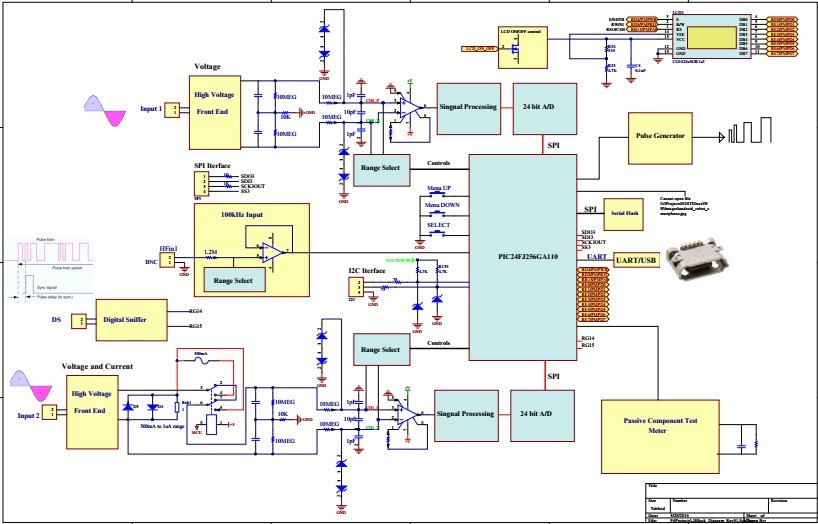
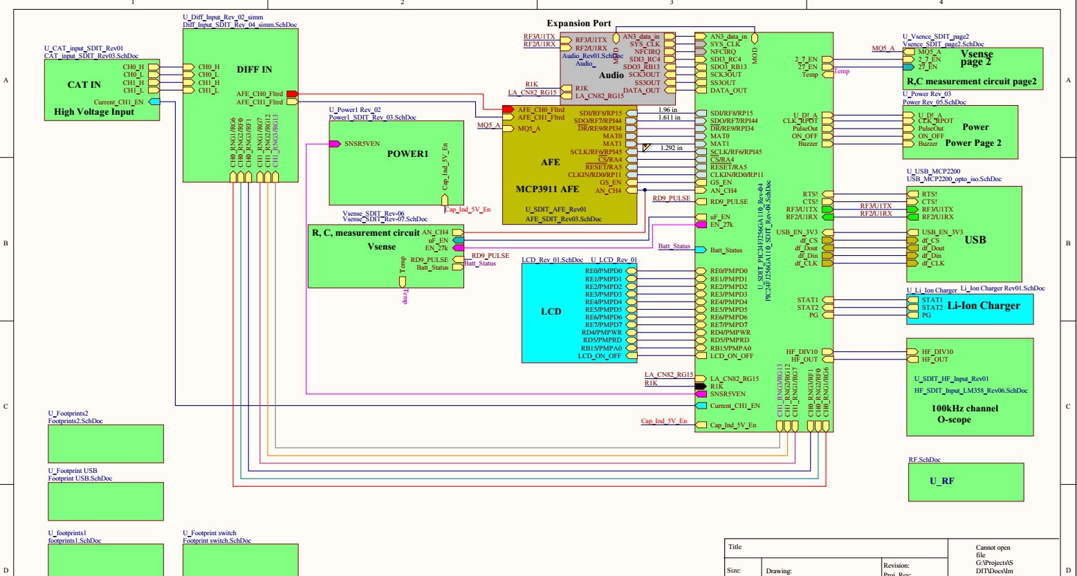
Main page of the project, shows all connections between the different parts of the schematics diagram:
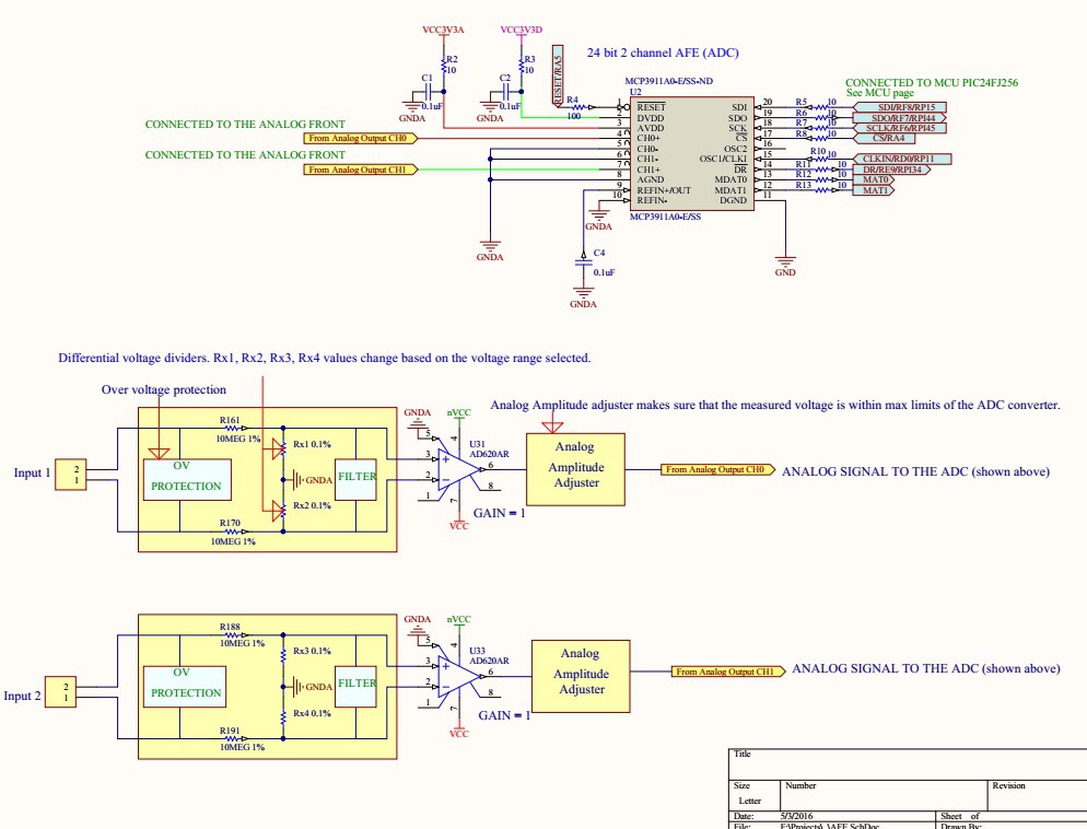
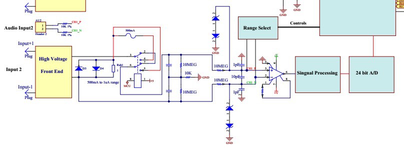
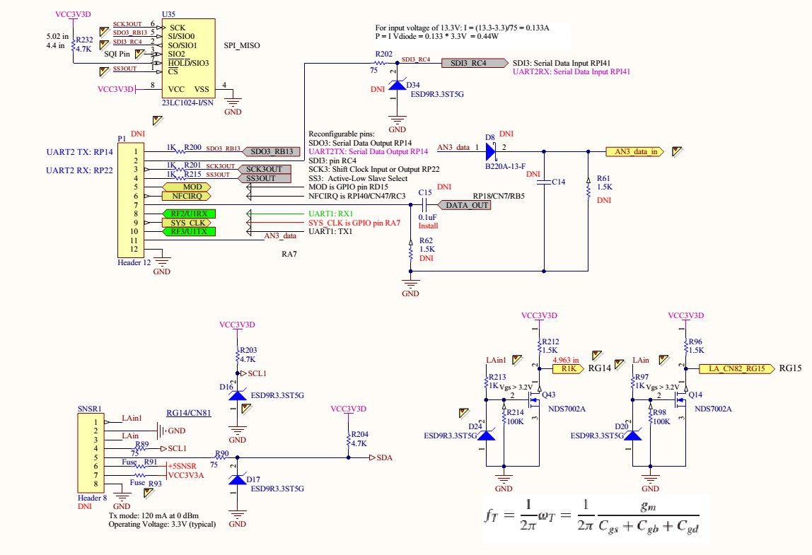
The instrument has two low frequency high voltage independent inputs for measuring signals and voltage levels below 1 kHz. On the block diagram above they are labeled as Input 1 and Input 2. The inputs are fully differential with over-voltage protection and filtering. Once the analog signal passed through the signal processing circuit it gets digitized by a 24 bit AFE (MCP3911). The MCP3911 is dual channel Analog Front End (AFE) containing two synchronous sampling Delta-Sigma Analog-to-Digital Converters (ADC), two PGAs, phase delay compensation block, internal voltage reference, modulator output block, and highspeed 20 MHz SPI compatible serial interface.
Voltage readings can be viewed on a built in LCD display or a PC user interface in real time. Input 2 can be set to measure currents up to 0.5A (I am working to increase the current range). When current measurement is selected the relay is switched to connect Rsh1 to the Input 2 terminal.
So far I was able to measure AC and DC voltages up to 120VAC, theoretically the instrument should work up to 220VAC or 310VDC.
There is a separate channel, o-scope, to view input signals up to 55 kHz with approximately 380 ksps on PC user interface. I am working on improving the sampling speed up to 500ksps. PIC24FJ256GA110 has 500ksps ADC converter, but because I have to manipulate and store data the effective sampling rate drops.
The following image shows the MCU circuit diagram:
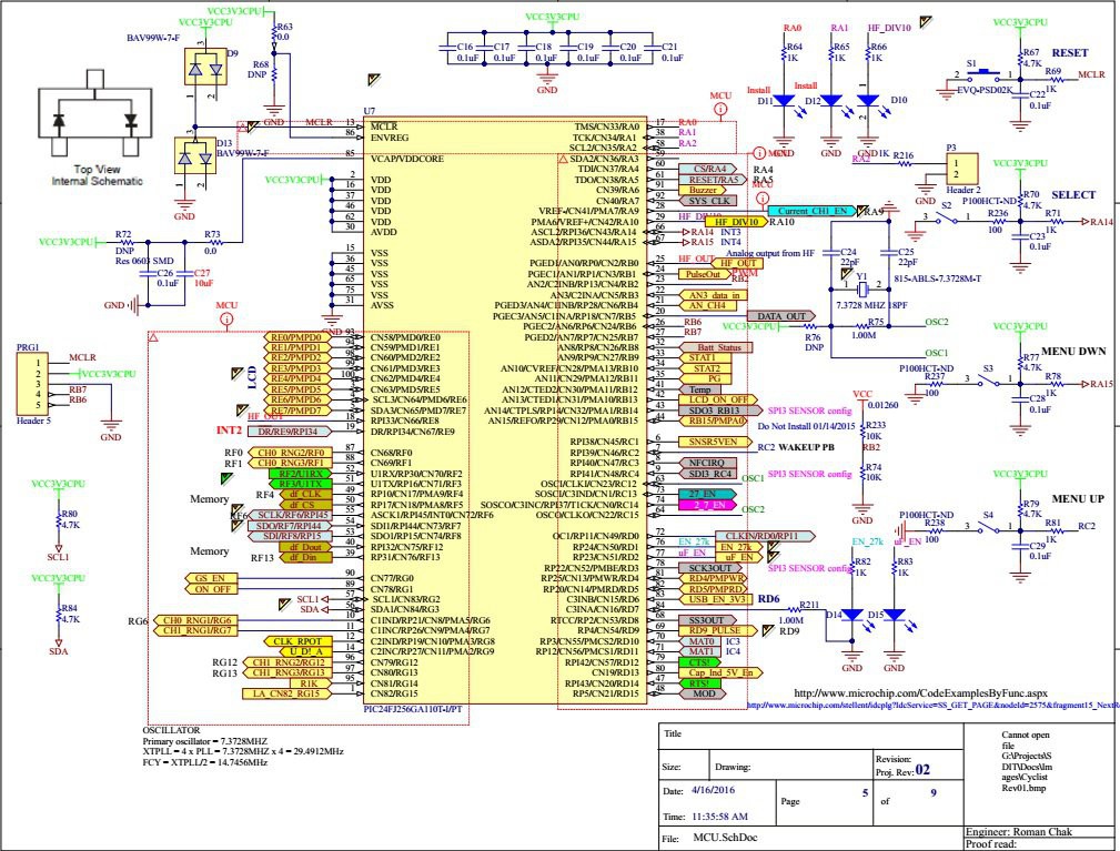
PIC24FJ256GA110 100 Pin General Purpose Flash Microcontroller with Peripheral Pin Select.
Central to all PIC24F devices is the 16-bit modified Harvard architecture, first introduced with Microchip’s dsPIC® digital signal controllers.
Ideal for low power (<100nA standby current) and connectivity applications that benefit from the availability of multiple serial ports (3xI2C, 3xSPI), 4xUARTS, and 23 independent timers. Large amounts of RAM (16kB) memory for buffering and large (up to 256kB) Enhanced Flash program memory make it ideal for embedded control and monitoring applications. PPS (Peripheral Pin Select) aids in configuring the most efficient pin configuration of available I/O, and CTMU provides touch sensing support for up to 64 individual buttons.
- Up to 16 MIPS performance
- 16 x 16 Hardware Multiply, Single Cycle Execution
- 12-bit x 16-bit Hardware Divider
- C Compiler Optimized Instruction Set
Internal serial flash used by the built-in data-logger:
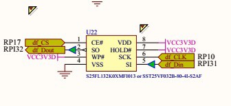
SPI bus used to transfer data from the MCU to the serial flash. The data-logger is currently under development.
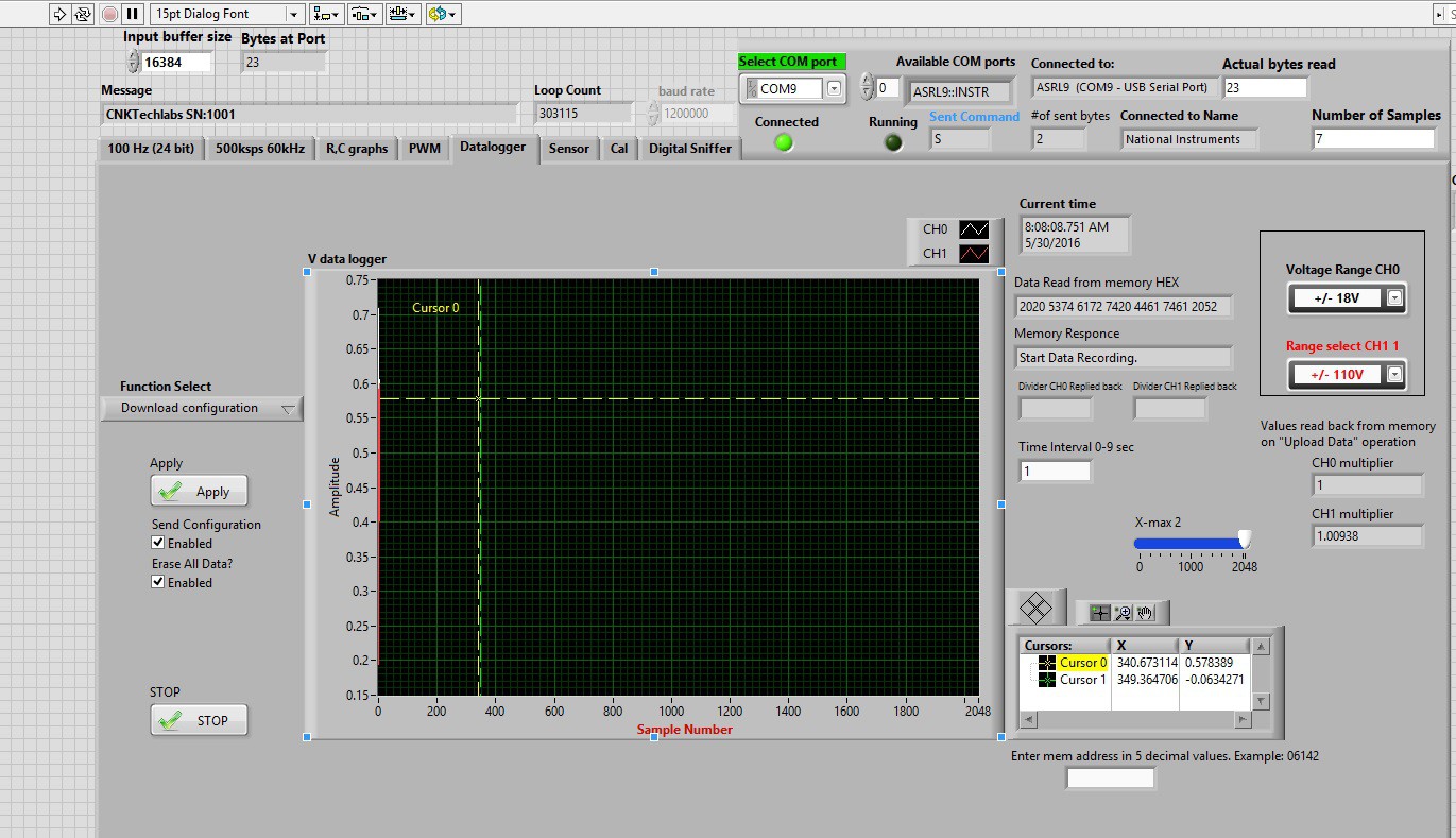
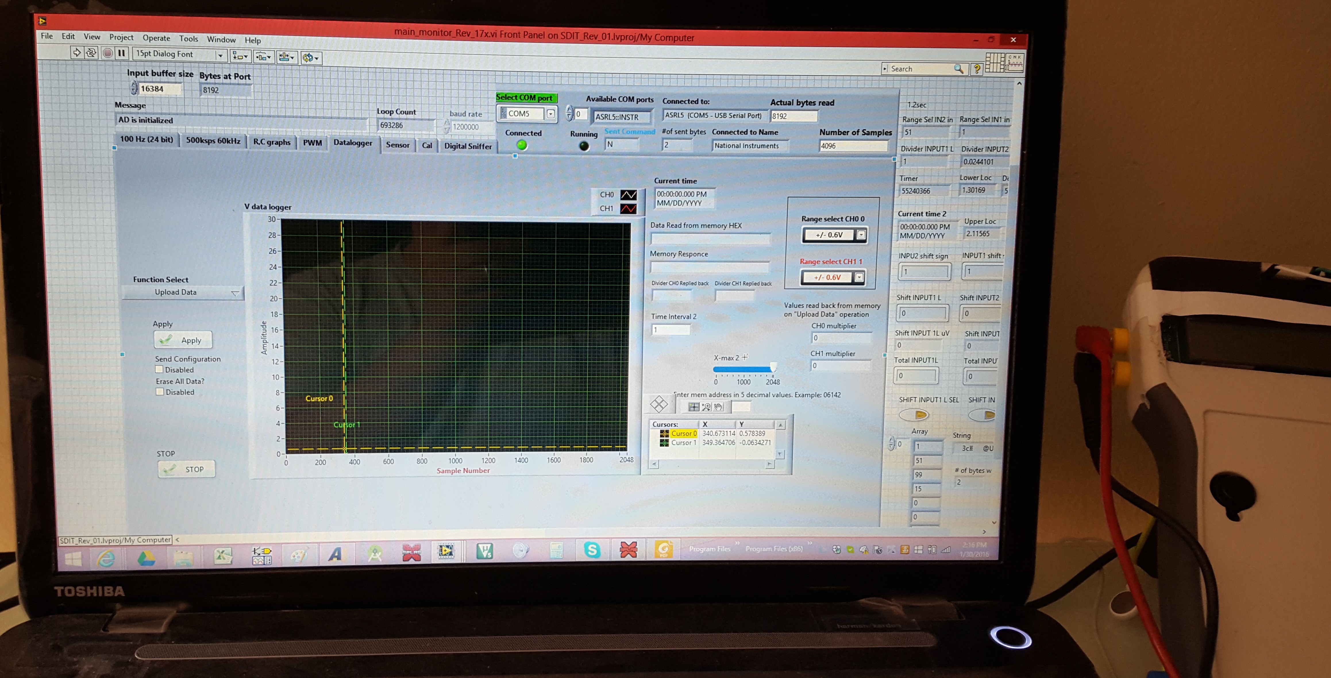
The following image shows "Download Configuration" page of the data-logger:
There is a separate input for resistance and capacitance measurements.
The on-board pulse generator output can be used to test electronic circuits.
Digital sniffer is a work in progress, it will be used to trace digital signals.
Internal serial flash memory allows data recording internally for later data view.
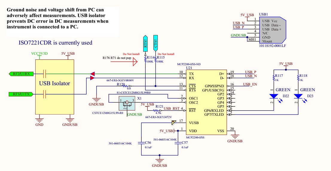
Galvanically isolated full speed USB port is used for transfer data at 1.2 Mbit/sec from the Multemeter+ to PC user interface. The isolation reduces effects of measurement distortions introduced by a PC.
The Multimeter+ runs on a rechargeable Li-Ion battery and has an on-board charging circuit.
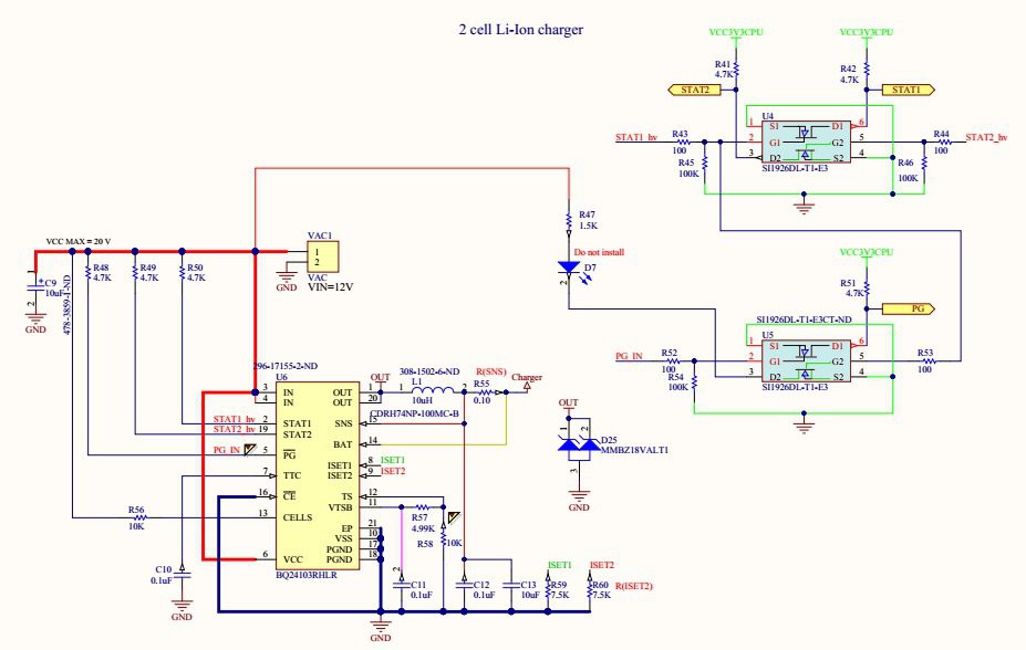
The charging circuit runs from a 12 VDC off-line converter. The main component is BQ24103RHLR Synchronous Switched-Mode, Li-Ion and Li-Polymer Charge-Management IC. U4 and U5 are used to monitor charging status of the battery. Battery status is displayed on the LCD display.
The expansion port that will be used for wireless communications and additional hardware, sensors.
Micro USB is used for serial communication between Multimeter + and a computer.
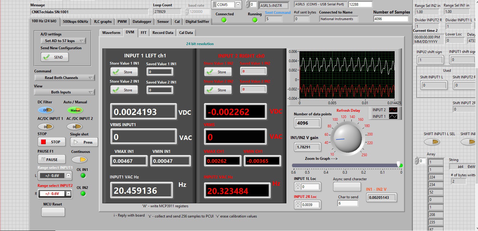
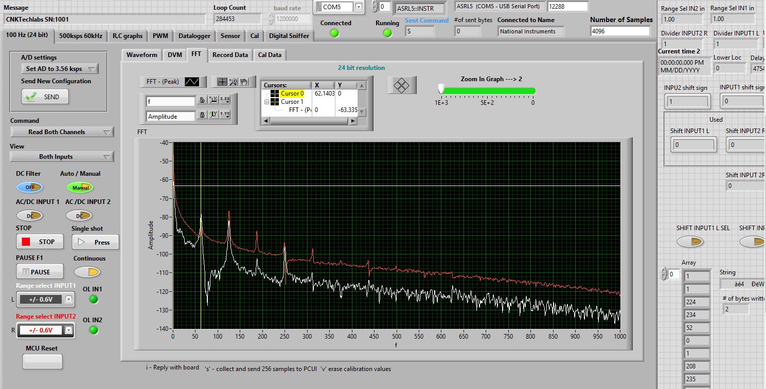
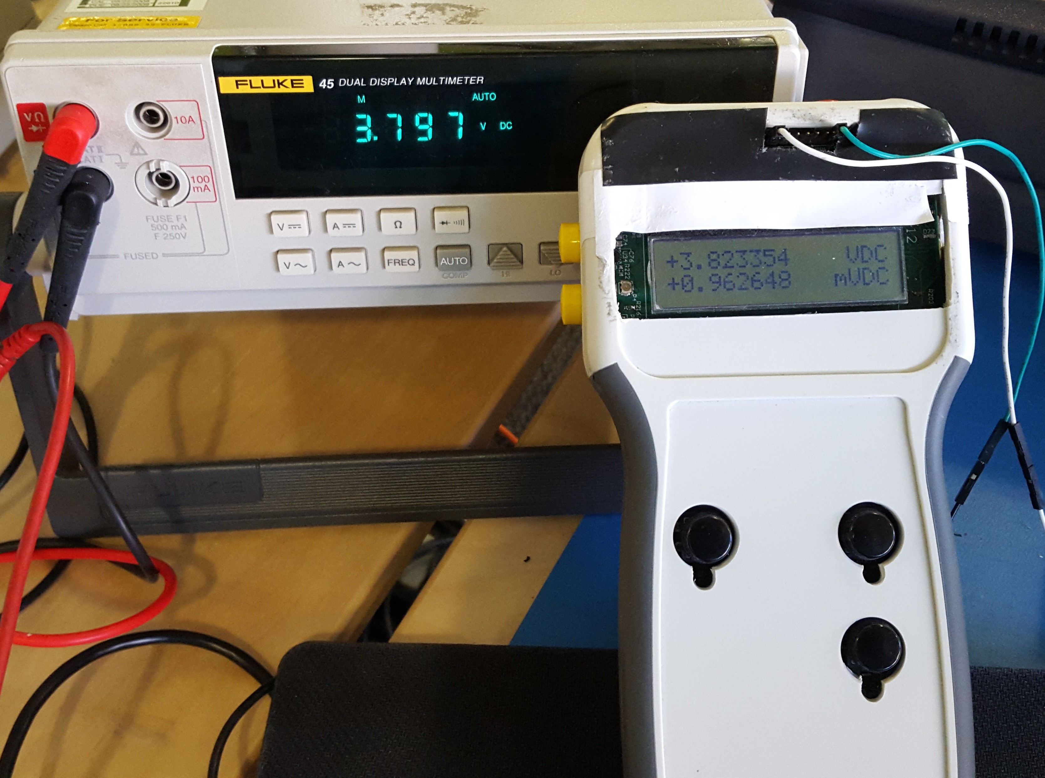
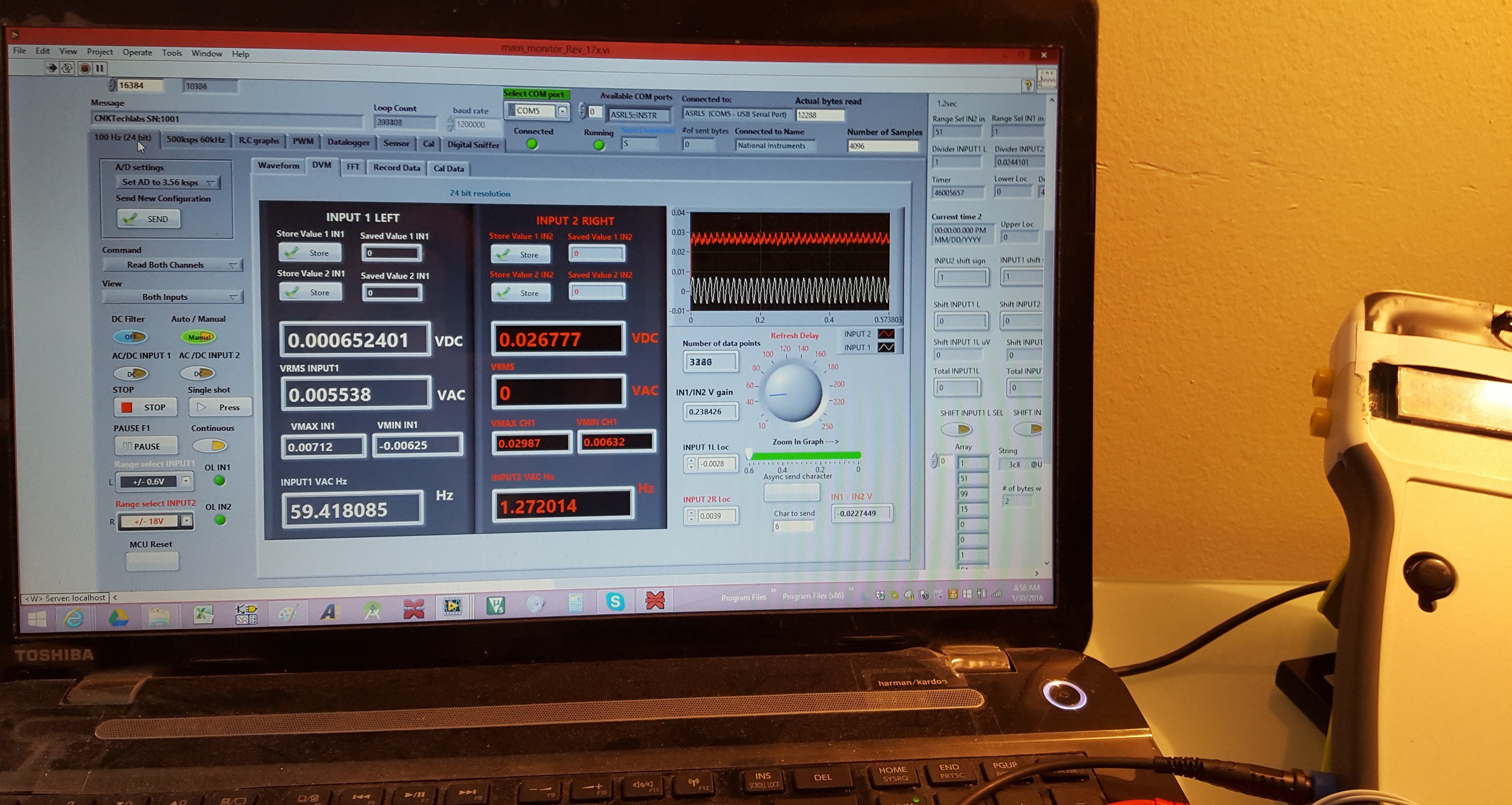
Measured values are displayed in real time. The following image shows a snapshot of a continuously running DVM (Digital Voltage Meter) page. On the image two small DC values are measured, the waveform graph shows noise riding on top of the DC voltages.
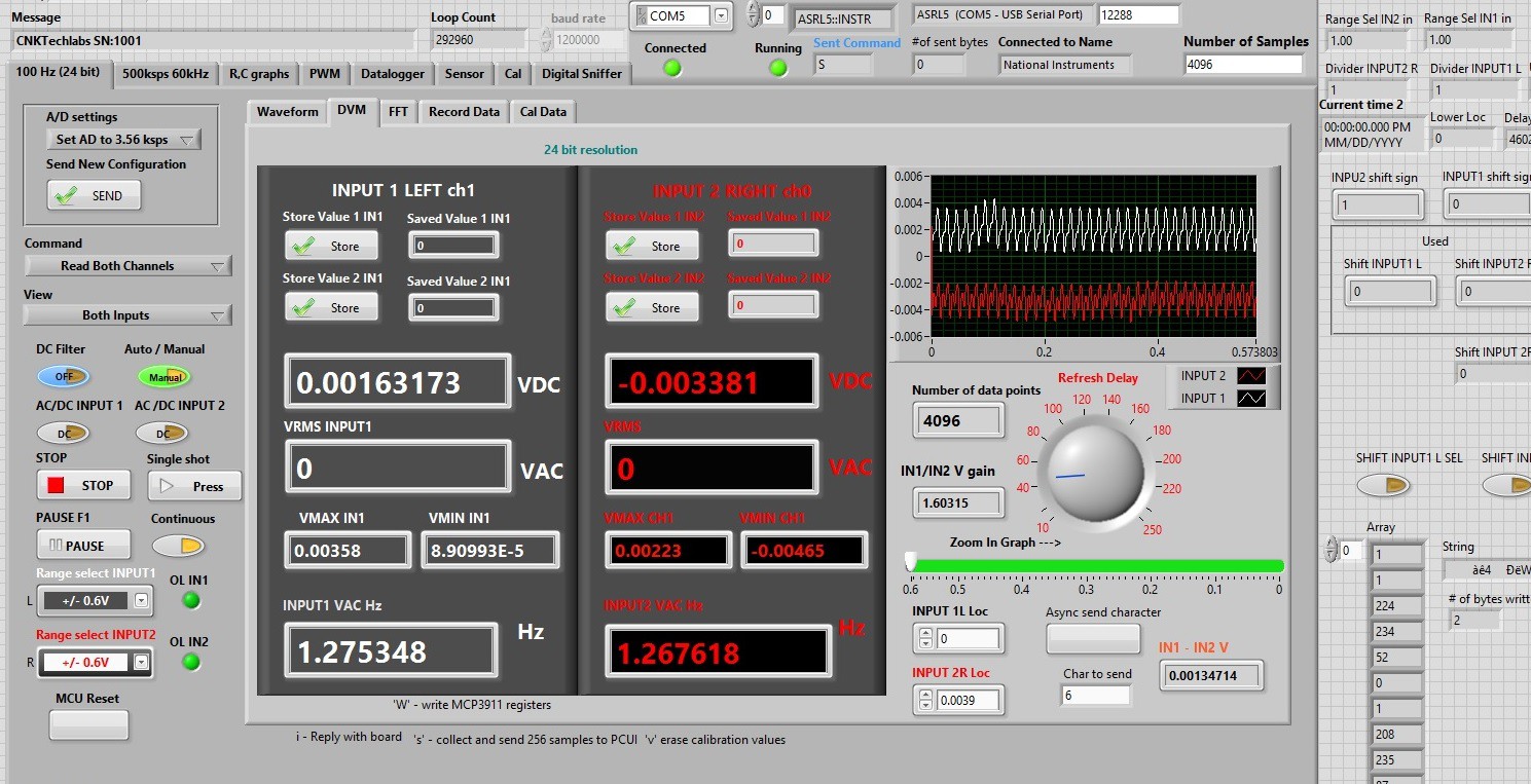
Sampling frequency can be switched between 3.56 ksps and 57 ksps. Switching to 57 ksps give a better noise picture
FFT page shows spectral picture of the measured voltages:
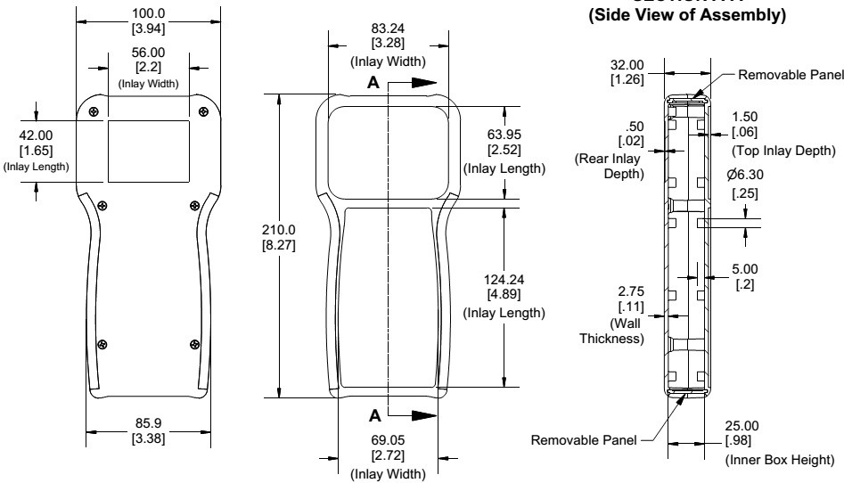
The Multimeter+ is designed to fit into Hammond 1553T case.
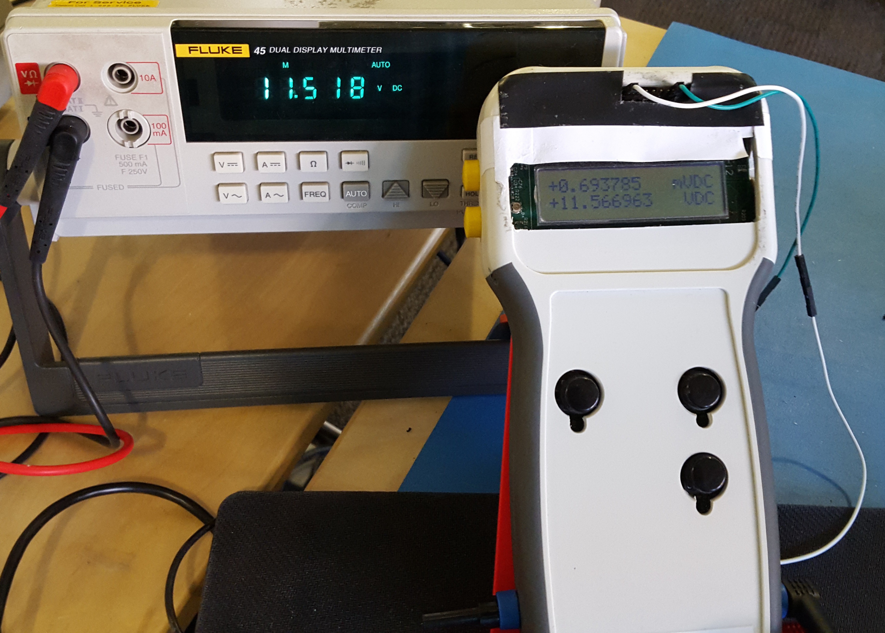
As probably most of EEs have, in my lab I use two Multimeters. The reason is that I often need to compare voltage reads from two different sources. If I have only one meter available and I need to compare two readings I either try to memorize the voltage read or I write it down to compare it later. This is not very convenient. Also, to compute power consumption voltage and current have to be measured at the same time. Multimeter+ solves all those problems by having a dual input. The instrument can be set to measure two different voltages or a voltage and current at the same time.
Video on taking DC Voltage reads on Input 2 (Bottom):
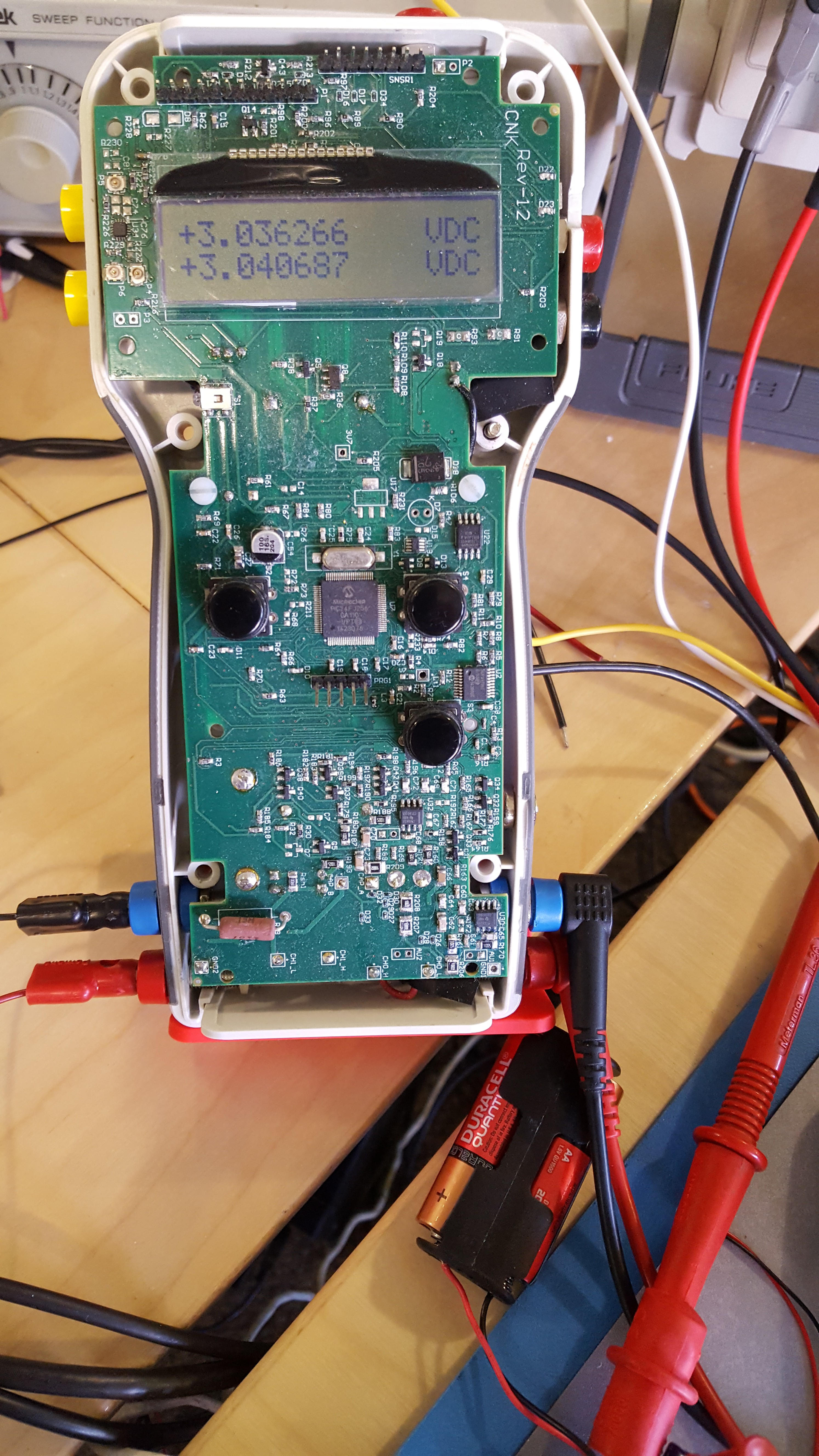
On the video I switch between waveform viewer, FFT frequency viewer, and chart display. I connected my o-scope input to an audio jack of my Bluetooth speaker. See the result :).The instrument is based on PIC24FJ256GA110 microchip microcontroller. It is powered by Li-ion rechargeable battery and can be used as a stand alone or USB test and measurement device.
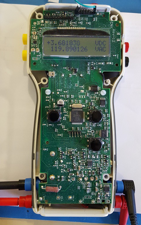
The following image is my device in all its beauty opened. It has two 24 bit fully differential channels with -3dB approximately 1 kHz. Sampling rate can be set to 3.56 ksps or 57 ksps. There are 4 automatically switching voltage ranges with lowest of 0 to +/-0.6V and highest of up to 400V maximum. Each channel is independent andcurrently has 10 Mega-Ohm input impedance (hoping to get 20 Meg) Both channels automatically switch between AC and DC measurements based on the input measured. AC values are true RMS readings. Channel 1 can be used to measure AC or DC current.
Readings can be viewed on PC via USB connection in numeric and graphical formats in real time. If you are testing a power supply and need to view low frequency ripple you may find this device quite helpful.
 The instrument has a single channel 10 bit resolution USB o-scope with approximate bandwidth of 55kHz (I am still testing frequency parameters to get more accurate values). The o-scope input has x1 and x10 ranges.
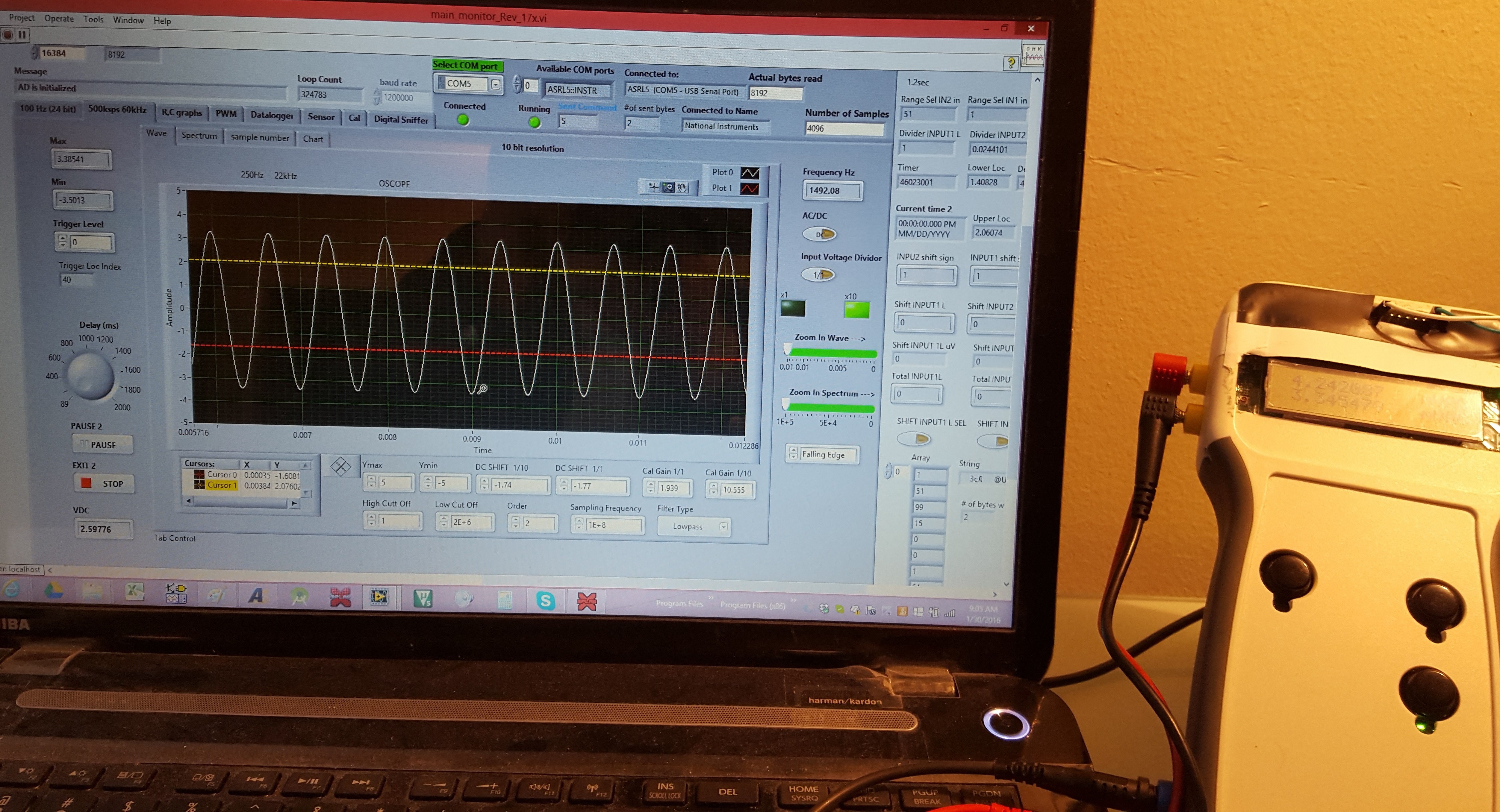
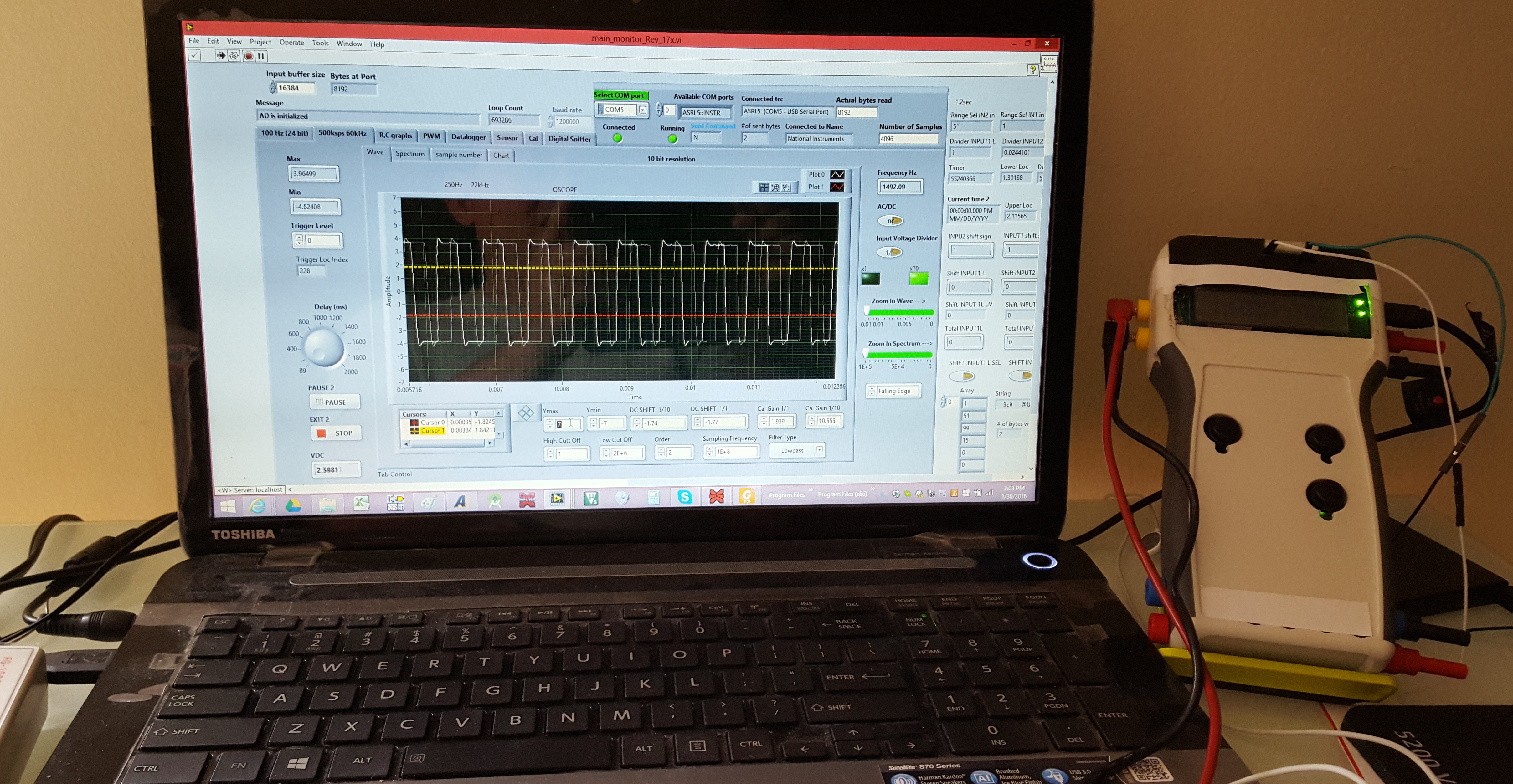
The o-scope I am still working on, there is a lot of testing and debugging to do.
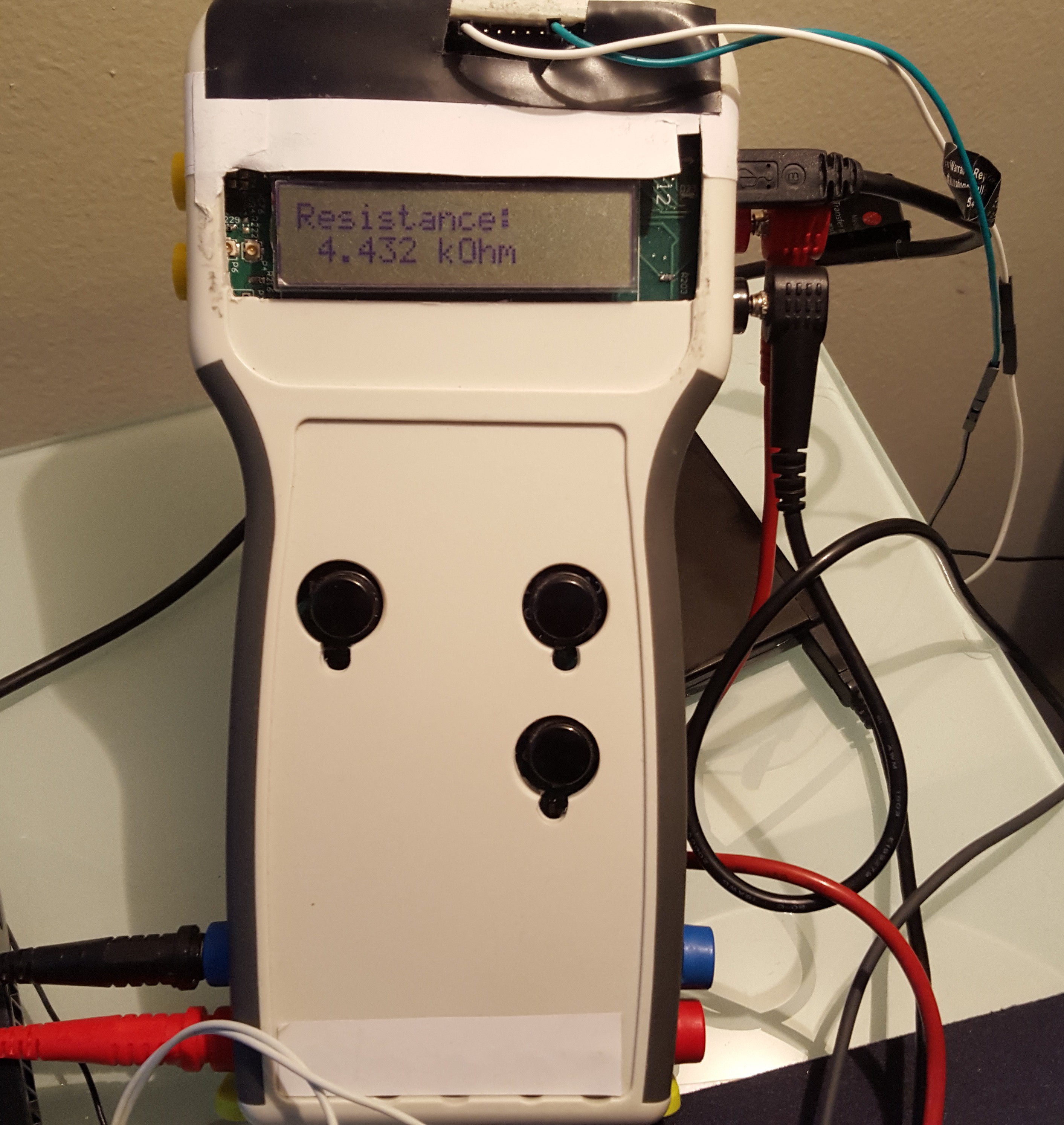
There are capacitance and resistance meters.
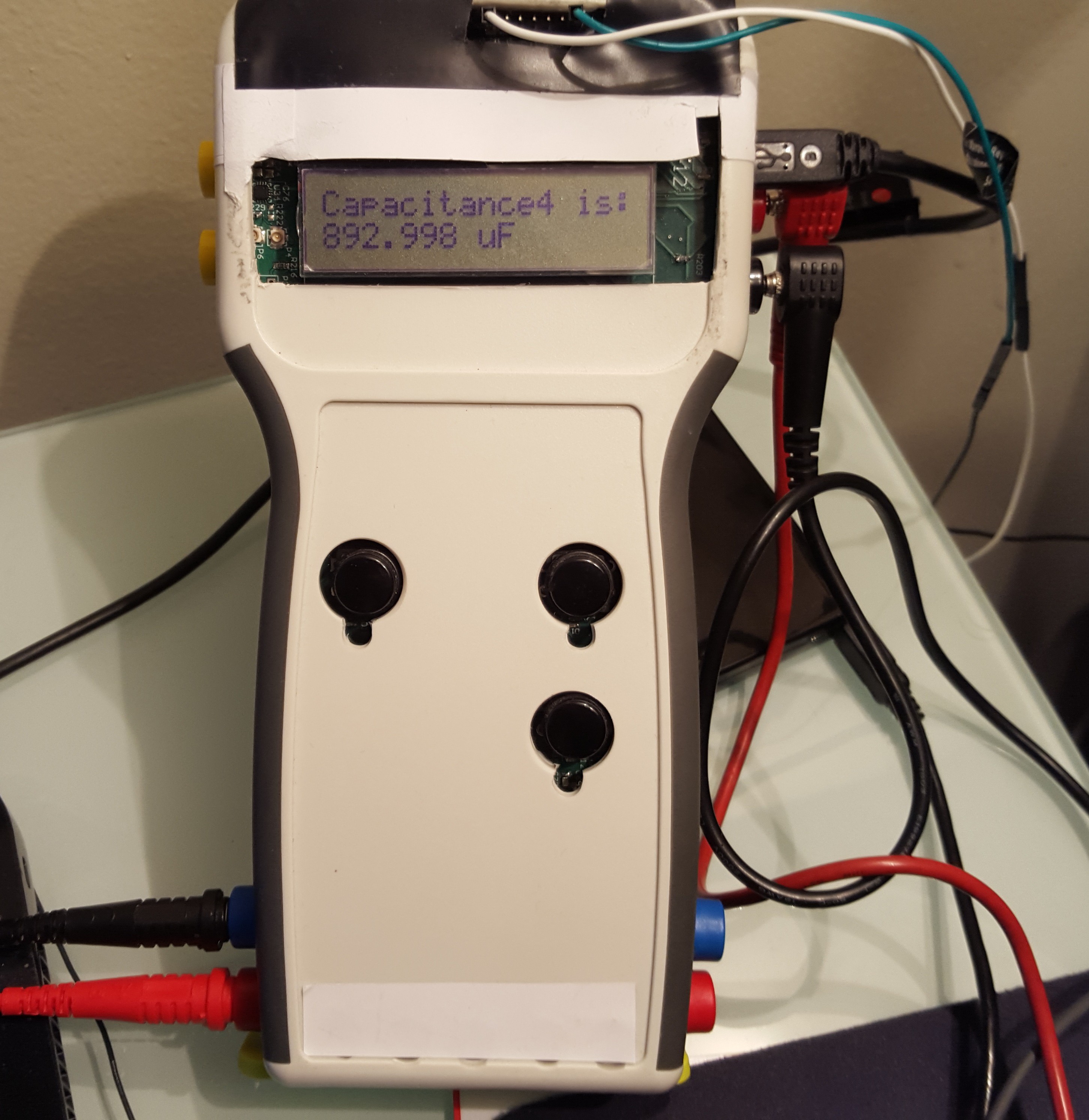 Capacitance meter has range from 15nF to approximately 2000 uF. Resistance measurement currently can be done from 2k-Ohm to 15 Mega-Ohm. I am working on the low resistances measurements, hopefully I can get down to 1 Ohm readings.
 I also have a 2 channel data-logger with 32 M-bit memory. This part is also under construction.
 To trace digital signals can be done with a built in digital sniffer. Digital sniffer is an input that drives an interrupt pin on the chip. Once an interrupt occurs I check the current status of the pin, "High" or "Low", and read my timer to determine the time from the last interrupt. The time interval indicates how many bits of data has been received. I am still working on this part of the project. I should be able to get it running by the next weekend and post a short video.
There is an expansion port on the instrument. It has a few GPIO pins UART, I2C, and SPI ports. Only 2 out three ports can be used at one time. I have used UART port to connect to a Nordic NRF51822 BLE device to run a simple wireless communication between my multimeter and my phone.
Computer sends a command and receives back data from the handheld.
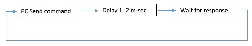
A command is a single character transfer from computer to the handheld. Device receives the character, decodes it, and runs corresponding section of code. For example when taking voltage measurements and collecting data on both channels ‘S’ character has to be sent to the handheld. When this character is received the unit starts conversion cycle. After the conversion is done firmware loads CH0 and CH1 data buffers with 24 bit results. When all buffers are full the data is sent back to PC. I use LabView to analyze and display data on PC. LabVIEW is a graphical programming language that makes it very easy to develop a custom user interface. The following is a partial list of character commands that are used to control and configure the unit from PC:
'i' - returns Board ID.
'p' - Pause acquisition.
's' - transmit 256 samples Start a new cycle.
'W' – write ADC registers
‘R’ – read ADC registers
Commands are sent via serial port. The device get assigned a COM port number once connected to a computer and communicates with LabVIEW through the COM port. Baud rate set to 1.2Meg per second. LabVIEW has many ready to use blocks for signal processing. Once data is received it can be filtered with low pass, high pass, band pass, or any other LabVIEW filter. LabVIEW has a signal processing kit, so all captured signals can be studied and processed.