 Roman
Roman Jasmine Brackett
-
CC3200 SimpleLink Development Page.
03/14/2016 at 15:08 • 0 comments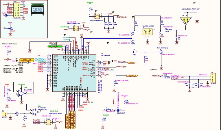
Step 1 is to add LCD and some analog interface to my CC3200MOD board. Schematics link.
CC3200 SimpleLink Wi-Fi and Internet-of-Things solution, a Single-Chip Wireless MCU.
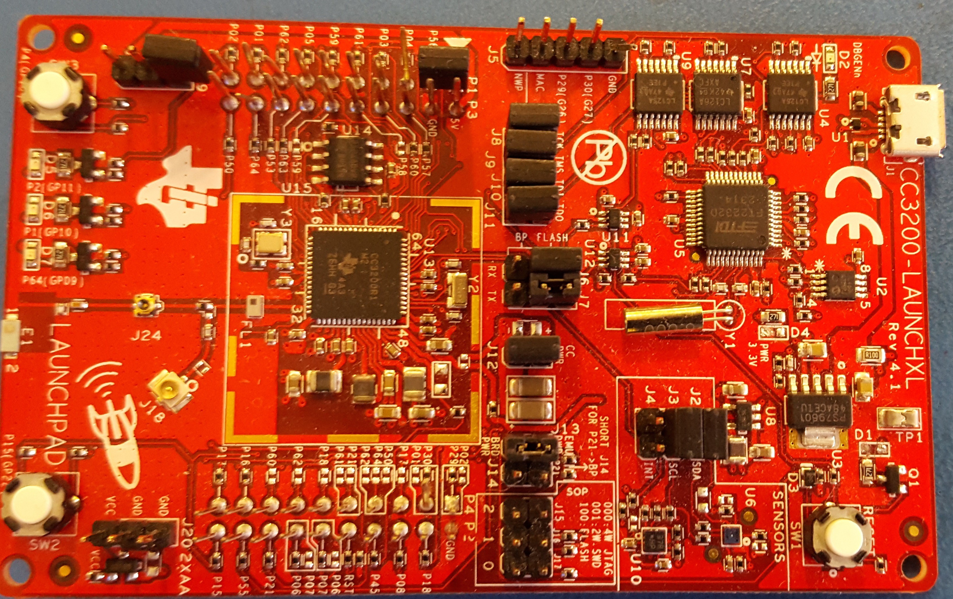
Another CC3200MOD board has arrived as well.
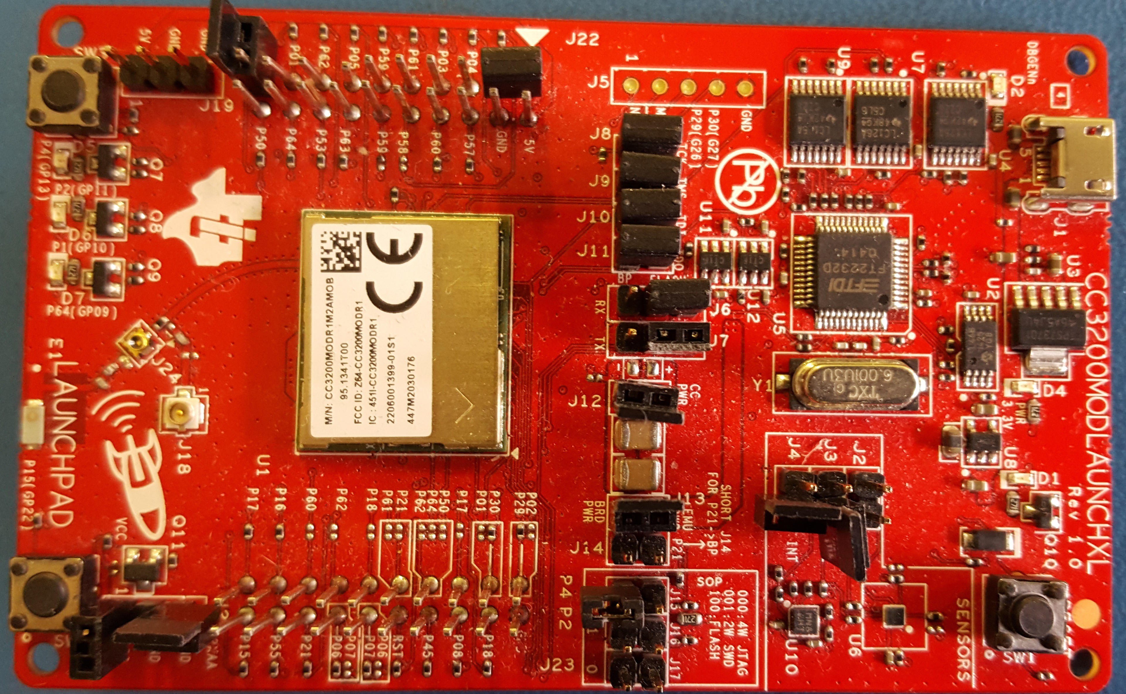
SimpleLink Wi-Fi CC3200 module LaunchPad
Going wireless is fun. My new toys have arrived.
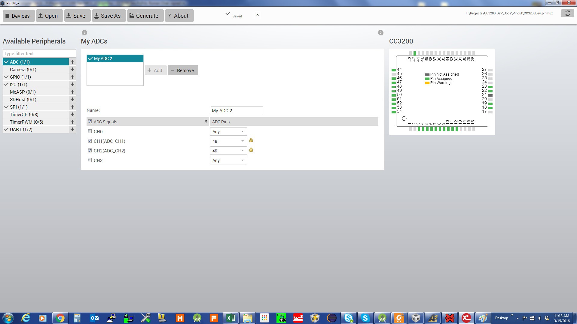
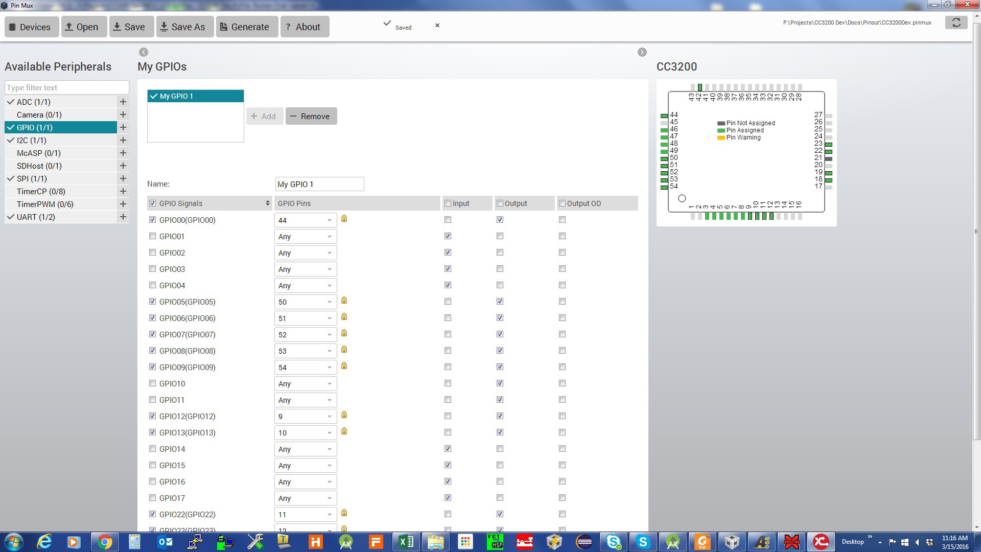
The next step is to set my pins in the code. Ti has a very handy tool for pin assignments Ti Pin Mux ToolPin Mux Tool.
The following are screen shots of the PinMax tool for the project:
Pin assignments for ADC:
Pin assignments for GPIO:
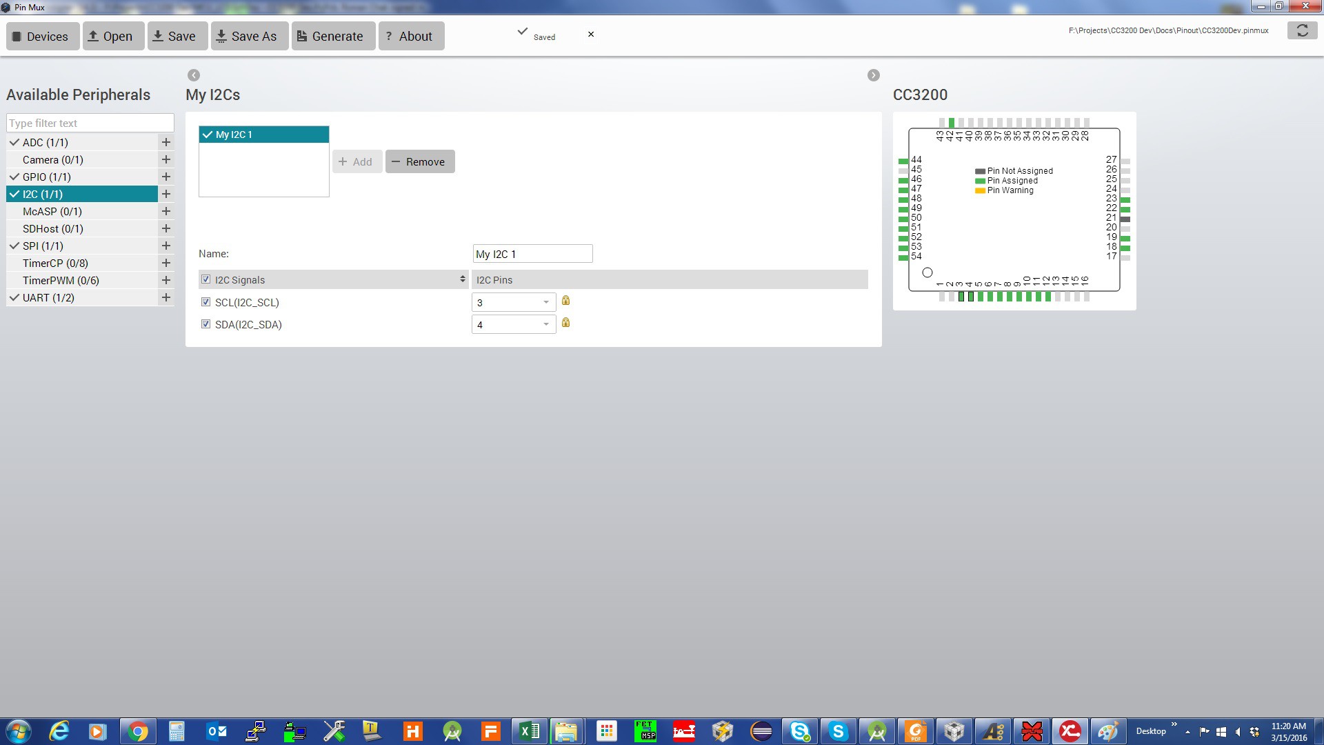
Pin assignments for I2C:
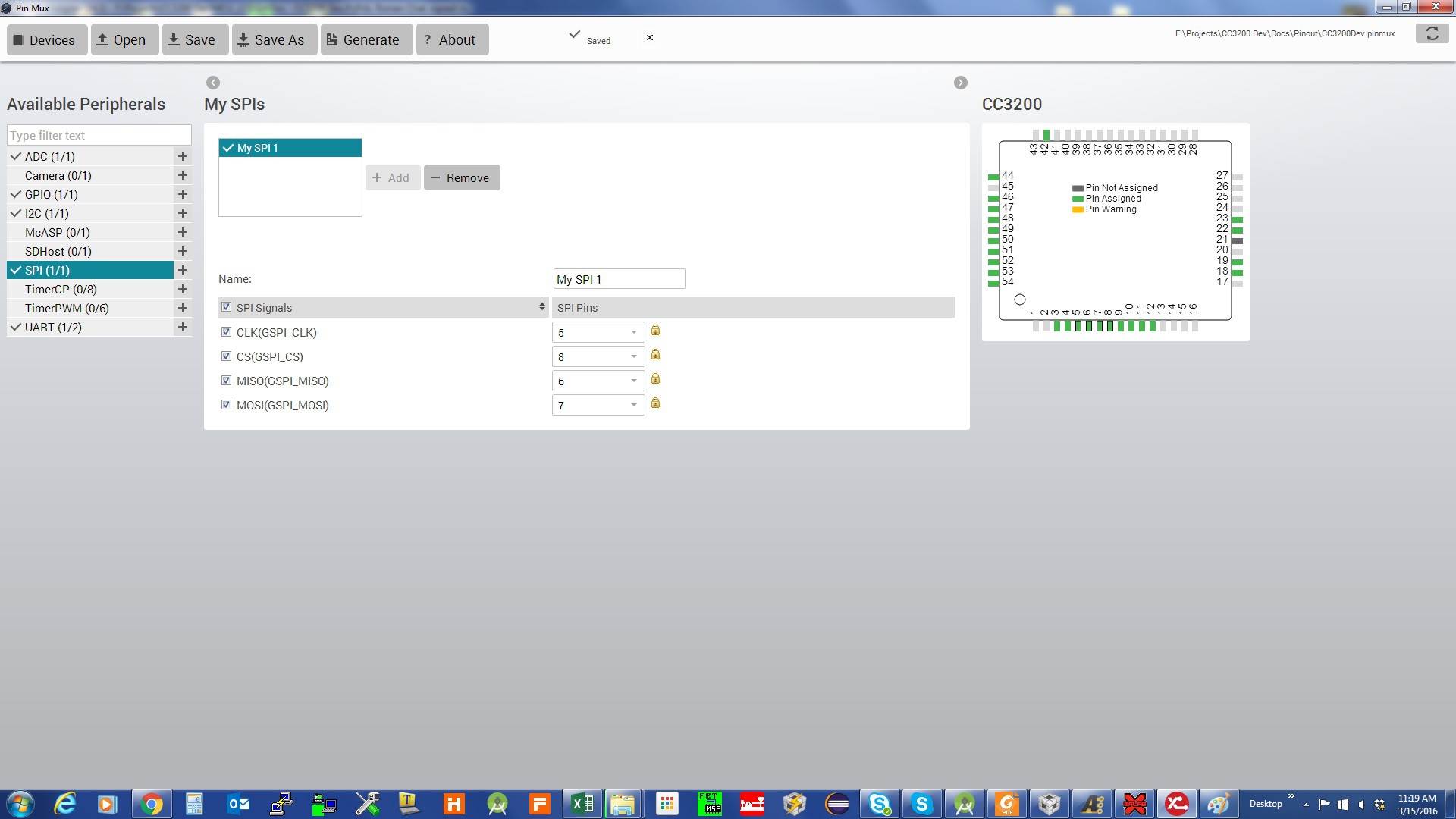
Pin assignments for SPI:
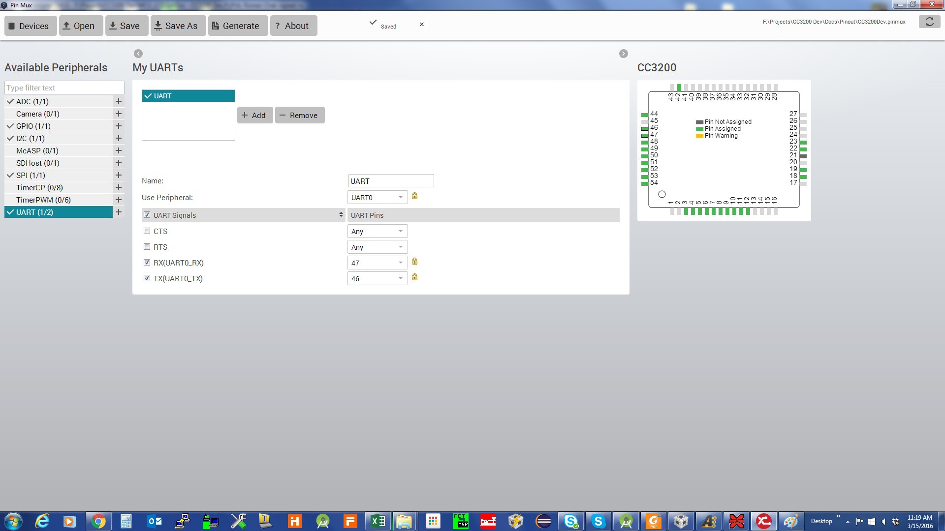
Pin assignments for UART:
The result is:
//*****************************************************************************
// pin_mux_config.c
//
// configure the device pins for different signals
//
// Copyright (C) 2014 Texas Instruments Incorporated - http://www.ti.com/
//
//
//  Redistribution and use in source and binary forms, with or without
//  modification, are permitted provided that the following conditions
//  are met:
//
//    Redistributions of source code must retain the above copyright
//    notice, this list of conditions and the following disclaimer.
//
//    Redistributions in binary form must reproduce the above copyright
//    notice, this list of conditions and the following disclaimer in the
//    documentation and/or other materials provided with the
//    distribution.
//
//    Neither the name of Texas Instruments Incorporated nor the names of
//    its contributors may be used to endorse or promote products derived
//    from this software without specific prior written permission.
//
//  THIS SOFTWARE IS PROVIDED BY THE COPYRIGHT HOLDERS AND CONTRIBUTORS
//  "AS IS" AND ANY EXPRESS OR IMPLIED WARRANTIES, INCLUDING, BUT NOT
//  LIMITED TO, THE IMPLIED WARRANTIES OF MERCHANTABILITY AND FITNESS FOR
//  A PARTICULAR PURPOSE ARE DISCLAIMED. IN NO EVENT SHALL THE COPYRIGHT
//  OWNER OR CONTRIBUTORS BE LIABLE FOR ANY DIRECT, INDIRECT, INCIDENTAL,
//  SPECIAL, EXEMPLARY, OR CONSEQUENTIAL DAMAGES (INCLUDING, BUT NOT
//  LIMITED TO, PROCUREMENT OF SUBSTITUTE GOODS OR SERVICES; LOSS OF USE,
//  DATA, OR PROFITS; OR BUSINESS INTERRUPTION) HOWEVER CAUSED AND ON ANY
//  THEORY OF LIABILITY, WHETHER IN CONTRACT, STRICT LIABILITY, OR TORT
//  (INCLUDING NEGLIGENCE OR OTHERWISE) ARISING IN ANY WAY OUT OF THE USE
//  OF THIS SOFTWARE, EVEN IF ADVISED OF THE POSSIBILITY OF SUCH DAMAGE.
//
//*****************************************************************************

// This file was automatically generated on 3/15/2016 at 12:31:19 AM
// by TI PinMux version 3.0.625
//
//*****************************************************************************

#include "pin_mux_config.h"
#include "hw_types.h"
#include "hw_memmap.h"
#include "hw_gpio.h"
#include "pin.h"
#include "gpio.h"
#include "prcm.h"

//*****************************************************************************
void PinMuxConfig(void)
{
    //
    // Enable Peripheral Clocks
    //
    PRCMPeripheralClkEnable(PRCM_ADC, PRCM_RUN_MODE_CLK);
    PRCMPeripheralClkEnable(PRCM_UARTA0, PRCM_RUN_MODE_CLK);
    PRCMPeripheralClkEnable(PRCM_GSPI, PRCM_RUN_MODE_CLK);
    PRCMPeripheralClkEnable(PRCM_I2CA0, PRCM_RUN_MODE_CLK);
    PRCMPeripheralClkEnable(PRCM_GPIOA0, PRCM_RUN_MODE_CLK);
    PRCMPeripheralClkEnable(PRCM_GPIOA1, PRCM_RUN_MODE_CLK);
    PRCMPeripheralClkEnable(PRCM_GPIOA2, PRCM_RUN_MODE_CLK);
    PRCMPeripheralClkEnable(PRCM_GPIOA3, PRCM_RUN_MODE_CLK);

    //
    // Configure PIN_58 for ADC0 ADC_CH1
    //
    PinTypeADC(PIN_58, PIN_MODE_255);

    //
    // Configure PIN_59 for ADC0 ADC_CH2
    //
    PinTypeADC(PIN_59, PIN_MODE_255);

    //
    // Configure PIN_55 for UART0 UART0_TX
    //
    PinTypeUART(PIN_55, PIN_MODE_3);

    //
    // Configure PIN_57 for UART0 UART0_RX
    //
    PinTypeUART(PIN_57, PIN_MODE_3);

    //
    // Configure PIN_08 for SPI0 GSPI_CS
    //
    PinTypeSPI(PIN_08, PIN_MODE_7);

    //
    // Configure PIN_05 for SPI0 GSPI_CLK
    //
    PinTypeSPI(PIN_05, PIN_MODE_7);

    //
    // Configure PIN_06 for SPI0 GSPI_MISO
    //
    PinTypeSPI(PIN_06, PIN_MODE_7);

    //
    // Configure PIN_07 for...
Read more » -
Simple Additive Mixer
03/09/2016 at 00:22 • 0 comments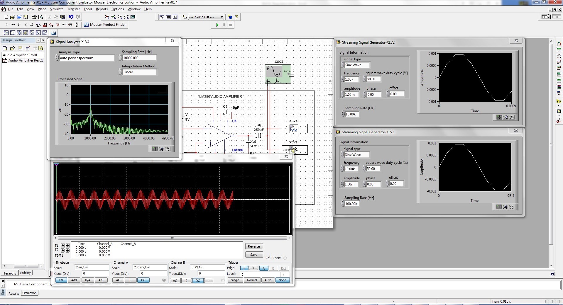
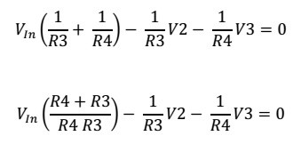
Simple additive mixers use Kirchhoff's circuit laws to add the currents of two or more signals together. When two different signals are applied to an input of an amplifier (assuming the amplifier input impedance is much higher than the source impedances of the two signal generators) they will add At Vin Junction point. Nodal analysis at Vin point gives:
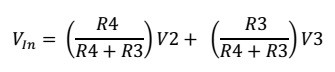
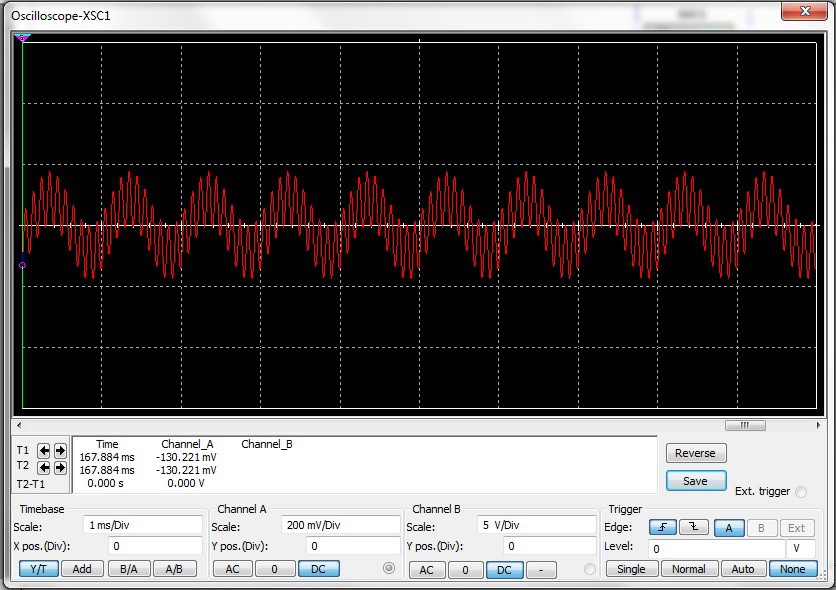
The following signal will be seen by the input of the amplifier:
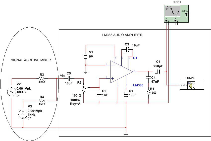
Amplifier with Gain = 200
Below is the output waveform.
The following image is taken from o-scope simulation in MultisimBLUE
The simulated sound can be played on a speaker. Double click on the speaker symbol.

Use "Multisim schematics file with audio output" example below. Run the simulation for a few seconds, then press "Play sound button" and you should hear the mixed simulated sound.
Used useful links:
LM386 simulation model: http://ecee.colorado.edu/~mathys/ecen1400/Software/LM386.cir
Create LM386 in MultiSIM BLUE: http://ecee.colorado.edu/~mathys/ecen1400/Software/CreateLM386.html
Multisim schematics file with an audio output.
Used MultiSIM BLUE for simulation.
-
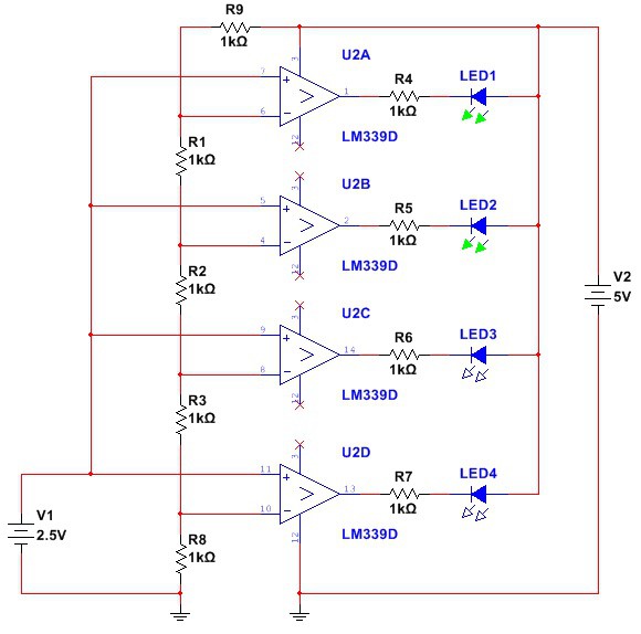
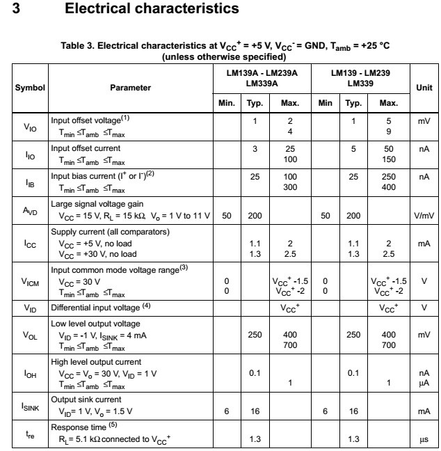
A basic volt-level indicator using LM339 comparator and a row of four LEDs.
03/03/2016 at 22:43 • 0 commentsI was going through my old files and discovered some circuits I have built some time ago. Avery basic LED voltage level indicator using LM339 can be used to indicate 4 voltage levels between 0 and 4V.
The basic circuit is shown below. Each comparator is biased one step higher than the comparator below it. As the input voltage increases and exceeds the reference voltage on the comparator's inverting input, the output goes high and lights its respective LED. Output sink current for the LEDs is approximately 6mA. It can be extended to 8 levels with an additional LM339 comparator. The circuit was simulated with MultiSIM BLUE.
My Projects
My Pages
Things I've Built
Multimeter +
Projects I Like & Follow
 joey castillo
 Applied Procrastination
 Ted Yapo
 ekaggrat singh kalsi
 Gilbert François
 Drix
Drix MG
MG Zack Freedman
 Brian Lough
 Josh Starnes
 Giulio Pons
 lukasz.iwaszkiewicz
 Sophi Kravitz
 Mauricio Martins
 Ivan Stepaniuk
Share this profile
ShareBits


Howdy! Thanks for the skull! Nice write-up on Instrumentation-amps, as well!

Very cool project. I'm thinking to get the parts and follow your instructions.
re: your/others' building it! Hey, somehow I hadn't even considered that a plausibility that others might actually try it, since it's a work-in-progress. But, I dig the idea, thanks for that! If you do, I'd love to hear your progress/experience!

Thanks for the follow! Admittedly, I haven't read up on #Handheld Electronic Test And Measurement Lab yet but it looks really interesting, as do your pages!
Thank you, l have a thing or two to share and publish. I hope it is interesting.
Thank you for the Like!