 deʃhipu
The PCBs from @oshpark arrived today, and I assembled one of them in the evening. Spent some frustrating minutes fighting with the programmer, until I realized that the wire connections were simply loose. After that, I quickly compiled the firmware (used CircuitPython 3.0alpha1 for Trinket M0, just modified the pin definitions, and made sure the gamepad library is compiled). When the USB disk appeared as it should, I copied the files from the prototype board I was using, and... nothing. The display doesn't seem to do anything.
Ok, let's make sure all the connections are solid, no shorts, the pins have correct voltages and the signals on them look good, the pin order is also good. The display worked before I desoldered it from the module, so what is wrong?
After much head scratching, I found the reason: the pull-up resistor the SAMD21 has on the reset pin is too weak for the display. After adding a 100kΩ pull-up on the back on the board, the display worked!
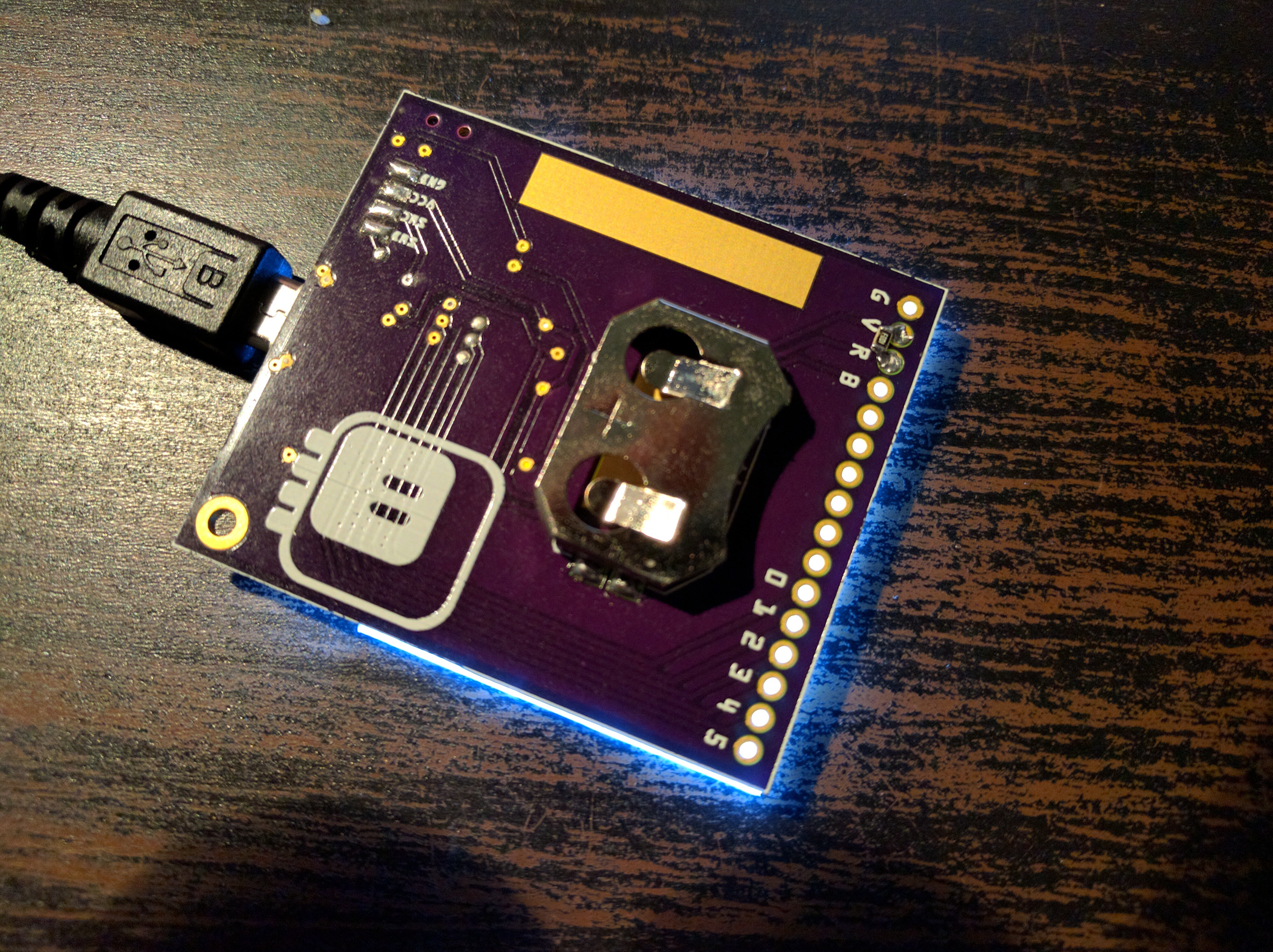
You can also see a large pad for soldering the clip — it is a badge, after all!
It also works with a LIR2302 battery, so that's great. I made it so that when USB is not connected, there is no backlight — this way the battery should last rather long. If you really need the light, you can connect the badge to a powerbank, I guess...
So this is one design that works, but we will see if we can do better. Tomorrow I should receive an e-ink display module for testing — I'm curious about how that one will work.
To summarize, Mark I has:
- 128×64 1.54" LCD display (with rather slow updates),
- backlight only working when powered by the USB port,
- SAMD21 chip with CircuitPython,
- a tiny (64kB IIRC) USB drive (using the flash on the chip),
- 6 buttons,
- switch that switches between the battery and USB power,
- 6 free GPIO pins broken out on the back,
- micro-usb port.
Discussions
Become a Hackaday.io Member
Create an account to leave a comment. Already have an account? Log In.