 Jarrod
As I found in the last post, the isolated UART bus daisychained through the Tesla modules is running at an odd frequency, 612,500bps. This is problematic as it is not a standard PC baud rate. I had an FTDI board lying around so I had a peek at the datasheet to discover it has a highly configurable baud rate generator, easily configured to within 3% of 612kbps. In addition, the windows driver handles configuration automatically.
To test this out I wrote a python script, PySerial was fine with the non standard rate, and the frequency was confirmed with a logic analyser.
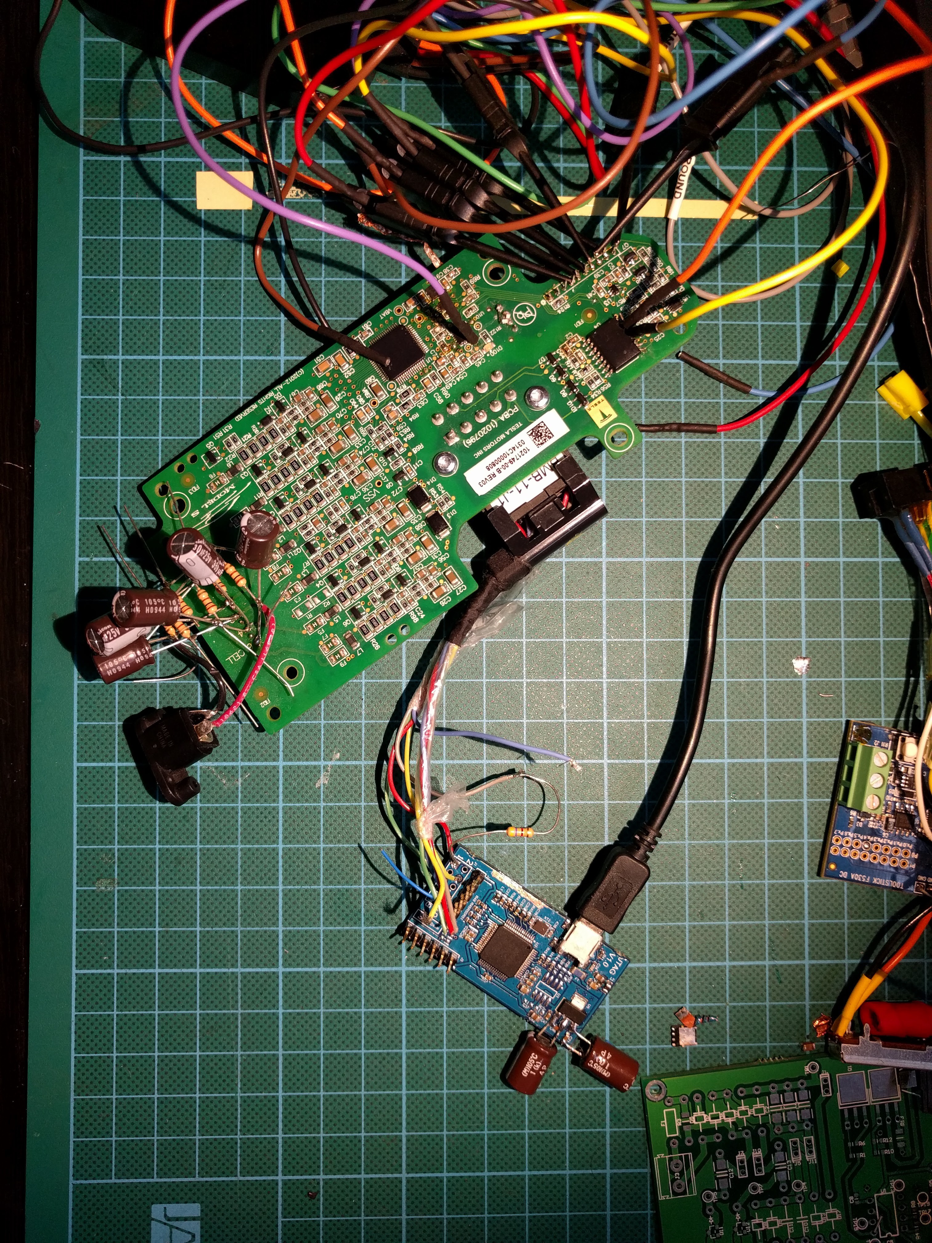
One of my collaborators, Tom has been probing out a module BMS hooked up to a master board, he found that a serial string is periodically transmitted and this results in SPI bus activity, just the status register being read. However, we had issues decoding the exact UART messages as he was lacking decent analysis tools. I Figured I would try repeating the test by sending the supposed data with my FTDI board anyway.
All I observed was each byte being repeated on the other side of the daisychain bus as expected from analysing the UART ISR code. I started modifying the bytes and noticed any string starting with 0x00 or 0x01 was repeated with that first byte modified to 0x80 or 0x81. At first I thought it was a read error but it was consistant and verified with a logic analyser.. Still no activity on the SPI bus.
Then a coding mistake led me to send long strings of 0x000000 etc. running the logic analyser I saw the SPI bus come alive!
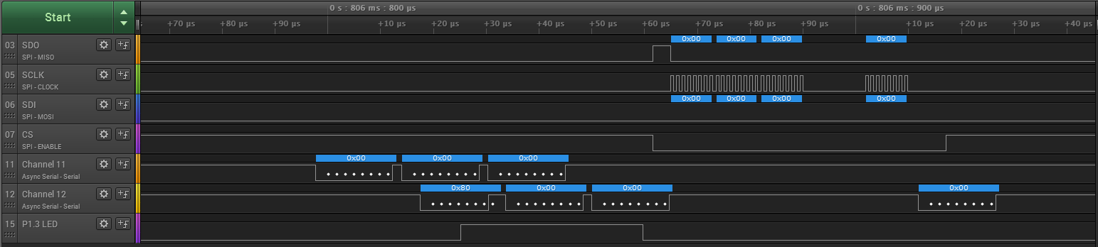
The UART responded with an additional 0x00. The SPI bus had repeated the 0x000000 message and added/read out a 0x00, It's like the microcontroller is acting as a UART/SPI bridge, with something funny happening on the first byte.
Working on this theory, I constructed a valid SPI read message according to the datasheet: http://www.ti.com/lit/ds/symlink/bq76pl536a-q1.pdf
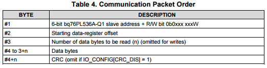
Lets try 0x00 00 01 - This should read 1 byte from device 0, address 0
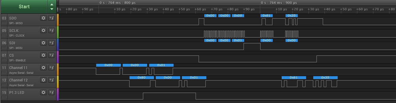
Taking it to the extreme, lets read out all the registers by sending 0x00 0x00 0x4C as there are 76=0x4C total register bytes
RX: 0x80, 0x00, 0x4C, 0x61, 0x00, 0x00, 0x00, 0x00, 0x00, 0x00, 0x00, 0x00, 0x00, 0x00, 0x00, 0x00, 0x00, 0x00, 0x00, 0x00, 0x00, 0x00, 0x00, 0x00, 0x00, 0x00, 0x00, 0x00, 0x00, 0x00, 0x00, 0x00, 0x00, 0x00, 0x00, 0x80, 0x08, 0x00, 0x00, 0x00, 0x00, 0x00, 0x00, 0x00, 0x00, 0x00, 0x00, 0x00, 0x00, 0x00, 0x00, 0x00, 0x00, 0x00, 0x00, 0x00, 0x00, 0x00, 0x00, 0x00, 0x00, 0x00, 0x00, 0x00, 0x00, 0x00, 0x00, 0x10, 0x80, 0x31, 0x81, 0x08, 0x81, 0x66, 0xff, 0x15, 0x00, 0x00, 0x00, 0x7F
SWEET!
Side note, looks like there is EEPROM data being loaded in for the UV/OV points and timers too. Translates to overvolt threshold of 4.45V and undervolt threshold of 1.5V, which seems very low to me.. I'm guessing the master BMS handles much of the protection by polling the cells. The GPAI ADC channel is also pointed to VBAT, so this channel is by default going to be measuring the voltage of all 6 cells in the module.
So taking a closer look at the first byte as this clearly differs from the SPI protocol and contains some undocumented magic. It's my best guess that bit 7 is used as a blocking bit to allow address assignment to each module. The middle 6 are the device address as per datasheet. So the last bit must be the R/W bit. (which is why both 0x00 and 0x01 have the bit7 blocking bit set when they are repeated)
I confirmed this by writing to the address register, then reading it back using the new address:
TX: 0x01, 0x3b, 0x81, 0x8b,
RX: 0x81, 0x3b, 0x81, 0x8b,
TX: 0x02, 0x3b, 0x01,
RX: 0x02, 0x3b, 0x01, 0x81, 0xba,
We write 0x81 to the address control register (0x3B), (where bit7 here indicates the address has been set, this clears an alert signal) so the new address is 0x01. to use the address, we must shift it left by 1, to get 0x02 as bit0 is the RW bit. The module now responds to the new address! In addition it no longer sets the 'blocking bit' - the leading byte is 0x02.
So if we try sending a message now to 0x00, it will be forwarded by this first module without modification:
TX: 0x00, 0x00, 0x01,
RX: 0x00, 0x00, 0x01,
The second module in the daisychain will then act on the string, set the blocking bit, and any other modules in the daisychain will thus ignore it, simply forwarding it on until it gets back to the master board (or in my case the FTDI serial interface)
Some other things I noticed, the on board microcontroller actually checks the CRC checksums for any write packets, it won't forward them over the SPI bus if they are wrong, this means we can't disable CRCs for SPI writes/replies on the BQ76 chip. The uC is clearly also recording the device address so it can handle the daisychain protocol and ignore packets not addressed to it. Broadcast packets are also supported (device address 0x3F)
So now anyone with an FTDI board (many other USB Serial interfaces may work too) communicate with a string of 1 to technically 63 tesla modules.
I've uploaded a Python script which sets the address of one module, then initiates an ADC conversion and reads out the result. I'll add more functionality and comments shortly, it can be found here:
https://cdn.hackaday.io/files/10098432032832/TeslaBMS.py
Or TeslaBMS.py in the files section of this project.
Next up: Designing an embedded BMS master board with a CAN bus and contactor (big DC relay) drivers.
Addendum: If you have a battery module pulled from a Tesla pack, it will still have the address it was assigned when operating in the Tesla, so it won't respond at the 0x00 address. Either reset it's address with a broadcast command or simply unplug the battery cable from the board. It's also worth noting that there is quite possibly a lot of extra functionality built into the microcontroller, the extracted code is vastly more complex than it should be for the above functionality. The function of the grey wire in the wiring harness is also unknown. likely a fault signal from the BQ76 BMS IC.
Discussions
Become a Hackaday.io Member
Create an account to leave a comment. Already have an account? Log In.
Hey Jarrod! We are currently trying to reverse engineer the BMS board on top of the gen2 Toshiba SCiB battery. Is this something you'd be interested in doing professionally?
Are you sure? yes | no
Cheers and keep up the great work! Hopefully you can create a plug and play kit for DIY'ers to utilize these battery packs as they become more readily available. Many Thanks!!
Are you sure? yes | no
I am proud of you. Congratulations! :)
Are you sure? yes | no
cheers indeed! Excellent job, I too joined to give a congrats
Are you sure? yes | no
This is great progress that you have made here, thanks for sharing.
Are you sure? yes | no
I signed up just to give you Congratulations on an excellent piece of detective work. I think this will prove to be an historic moment. Jack over on EVTV will be pleased. Why are you considering your own master board - rather than cracking the existing Tesla master pcb?
Are you sure? yes | no
Cheers! I don't have an existing tesla master board. Also I want to build a charge controller into it.
Are you sure? yes | no