 georg ottinger
For the second use case I wanted to try design a 30dB DIY-Attenuator. I used this attenuator calculator (german) to calculator the resistors for a PI-configuration at 50 Ohm input and output impedance. I needed to place 53.3 Ohm and 789.8 Ohm resistors – in order to generate the right resistor values – I choose to put for each resistors, two resistors in parallel. The needed values I calculated with the tool pointless-resistance, which automatically searches the values of the E-Series for suitable candidates within a defined tolerance.
for 789.8 Ohms – I used 820 parallel with 22k – which results in 790.5 Ohms
for 53.3 Ohms – I used 56 parallel with 1k2 – which results in 53.5 Ohms
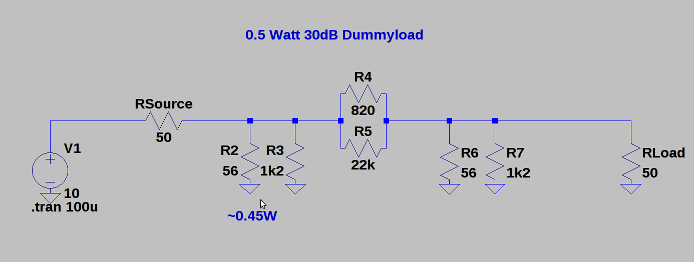
In the Simulation you can see that major share of the power has to be dissipated by the lower resistor close to the input. The 0603 Resistors I am using have a power rating of 100mW which is the limiting factor. 100mW translates to 20dBm which is enough for my experiments. (see Watt-dBm converter) – But a more clever solution would be to use different resistors in physical size, because in our schematic only R2 has to dissipate the majority of excess power. For example a 1218 Resistor would be sufficient enough for 1Watt / 30dBm. (See resistor sizes and power dissipation)
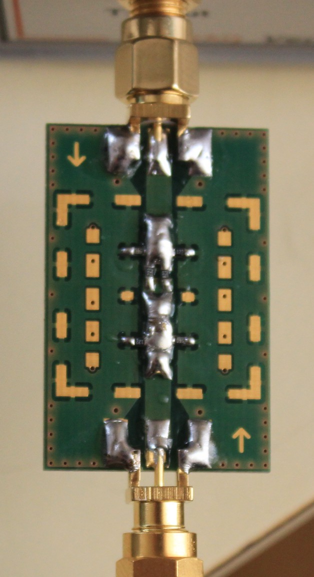
After the math it is time for solder – and the result looks like this:
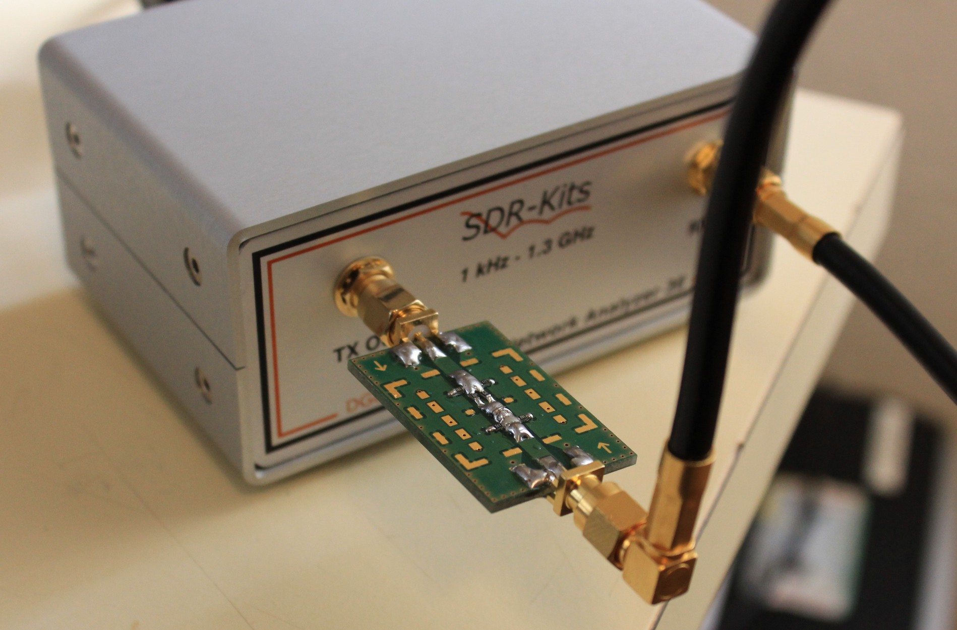
And to measure its performance lets connect it again to the VNA:
Measurement results in the Range 1-500 Mhz:
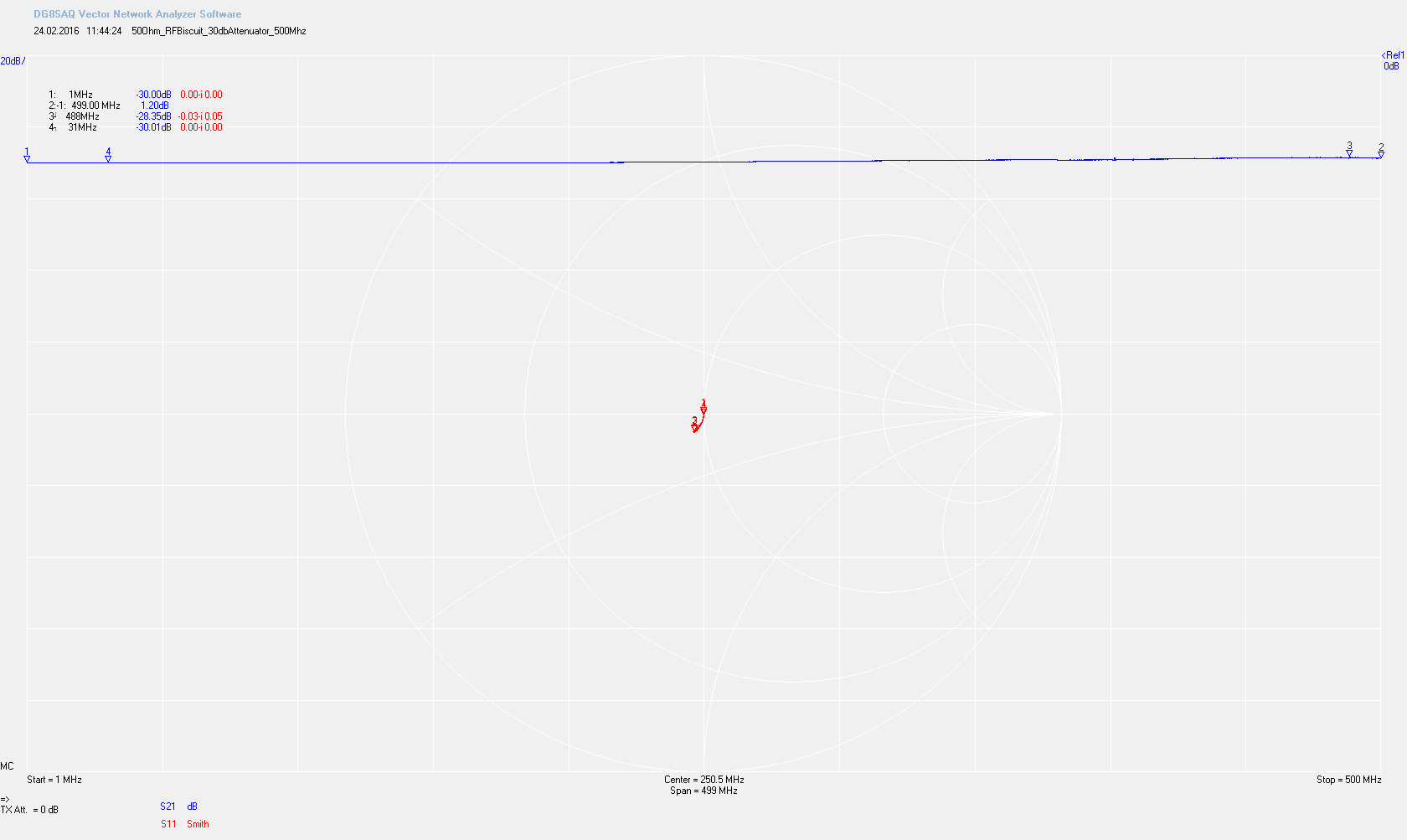
We are pretty close to our 50 Ohm impedance. The flatness of the attenuation ranges from -30.01 dB to -28.35 dB. The parasitic capacitance already start to show up a little.
Measurement results in the Range 1-1000 Mhz:
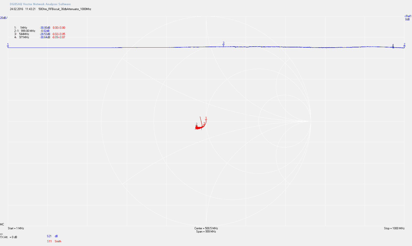
The parasitic capacitance are getting stronger and flatness is -30.64 to -28.53dB
I conclude that the attenuator is good enough for my “lowfi” experiments. But lets compare it to a commercial available attenuator (specified up to 3Ghz).
commercial -20dB 3Ghz Attenuator (1-500Mhz):
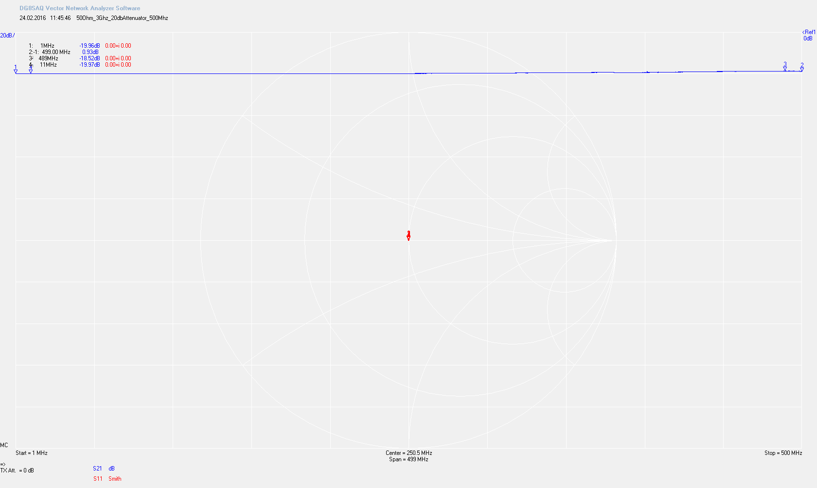
The impedance is just a spot (the vertical lines that are visible are only the markers). Flatness is: -19.97 dB to -18.52dB
commercial -20dB 3Ghz Attenuator (1-1000Mhz):
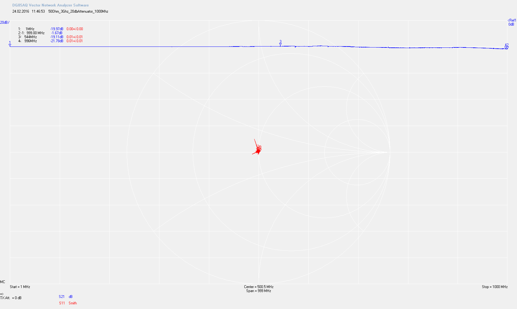
The impedance is still spot on – although you can see spurs which are related to the measurement. The spot is a bit broader because the accuracy of the VNA degrades a little above 500Mhz The flatness is: -19.11 dB to 21.78 dB
Discussions
Become a Hackaday.io Member
Create an account to leave a comment. Already have an account? Log In.