Close
0%
0%

ChaiBot

Tea Steeping robot that starts a timer when cups are filled with hot water and lifts bags automatically to make perfect tea every time.

Similar projects worth following
Tea Steeping robot hacked from CD Drive

My first Hackaday.io project write-up is a Tea making machine that me and my Son Oliver started last summer during his break from Uni. It's been gradually updated and upgraded to the point where it's become an indispensable kitchen appliance. The motive for the build was simple... we were both pouring boiling water onto teabags in a cup and then wandering off and forgetting them - only to remember 10 minutes too late.

The ideal solution was therefore a device that would dunk one or two bags for a preset time and them raise them from the cup automatically. To get the bags moving, we settled on an old CD drive stood on end. To the CD tray we fitted a stainless steel mesh cut and folded into two holders for the teabags. All the control is handled by a PIC 16F887 which is woken by a push on the paddle that presses down on the eject button. A transistor H-brige runs the original motor and everything is powered by 4xAA batteries.

Finer points are a rotary encoder for setting the steeping time and a capacitive "load sensor" that detects when the water is poured to start the timer. The same sensing is used to determine that the cups have been removed at the end of the process.

We think the automation is about as complete as it could be now. To make tea, one press on the paddle turns on the device and the gantry rises - tea bags are inserted, cups placed and a final press lowers the gantry + bag(s) into the cup(s). Pouring in water from the kettle starts the timer so once poured we just walk away.

At the end of the timing period the gantry is lifted and, as of this year, a notification is sent over WiFi to PushBullet using an ESP8266. After the cups are removed the gantry is lowered and the device goes into low-power standby.

The construction is mostly laser-cut 6mm ply with a smoked acrylic window for the display and mirror acrylic for the edge-lit paddle on top. This part has an engraved finger that hints at what you should do to operate the Tea machine


main.hex

Compiled hex

hex - 16.96 kB - 04/03/2016 at 10:17

Download

display.c

Include (CCS compiler)

C Source File - 10.95 kB - 04/03/2016 at 10:02

Download

main.c

Main C source (CCS compiler)

C Source File - 17.61 kB - 04/03/2016 at 10:01

Download

ChaiBotCCT3of3.jpg

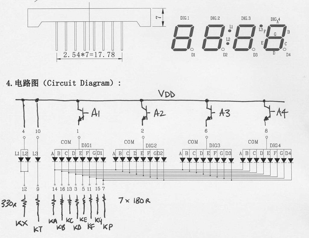
LED Display

JPEG Image - 76.92 kB - 04/02/2016 at 17:55

Preview

ChaiBotCCT1of3.jpg

PIC Chip connections

JPEG Image - 115.50 kB - 04/02/2016 at 17:53

Preview

View all 6 files

  • 1 × Old CD or DVD drive
  • 1 × PIC16F887 Microprocessors, Microcontrollers
  • 1 × 4MHz crystal
  • 2 × 18pF Ceramic Capacitor
  • 1 × 10K Resistor

View all 25 components

  • Calibration

    Adrian04/03/2016 at 10:56 0 comments

    The capacitive load sensor readings can be monitored and a detection threshold set for cup sensing (both for auto timing & auto shutoff) by entering "test mode". This is performed by pressing the paddle switch and holding it down until TEST appears on the display. A reading of something around 1000 should be expected without any weight on the cup base and the value should go up as cups and water are added (or you simply press down on the base).

    While in test mode, turning the rotary encoder will alter the stored threshold setting. This value defaults to 200 but can be adjusted to suit the build. This threshold is used in two places:

    1. After empty cup(s) are placed and the gantry is lowered, the capacitive reading (weight) is noted. The threshold is now used to detect the pouring of hot water to automatically start the timer. I.e. weight has increased.
    2. When steeping has ended and the gantry is automatically raised, the threshold is used to determine when the cup(s) have been removed. I.e. weight has decreased.

    Because of 2. a three-second delay has been introduced before the gantry is lowered following cup removal detection to allow time for both cups to be removed. A possible refinement would be to use the weight increase (as measured between the point when the empty cup reading was taken, and at the time when steeping terminated) and only perform auto shutoff when more than half this weight was removed.

    To exit test mode (and as general rule to shut down the device) press and hold down the paddle.

  • Initial fettling

    Adrian04/01/2016 at 21:30 0 comments

    With the initial design, the power supply was just 4xAA feeding the PIC + motor bridge etc. The idea was to eliminate the need for a regulator as the batteries could be expected to be between 1.6V max and 1.1V min. and by introducing a silicon diode in series with the battery supply, we get battery reversal protection and a 0.7V drop to keep Vdd within safe limits. This worked fine with fresh batteries but after around one weeks use the gantry motor didn't get enough power to lift two wet teabags.

    The volt-drops were all adding up: e.g. 1.3V at each AA minus 0.7V diode drop meant only 4.5V was feeding the Vdd rail. 0.2V in the PNP side of the H-Bridge plus another 0.4V lost in the steel battery springs (has anyone else noticed how resistive these things are?) all conspiring to make the motor stall out.

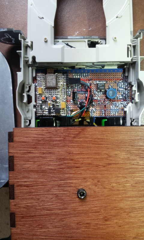
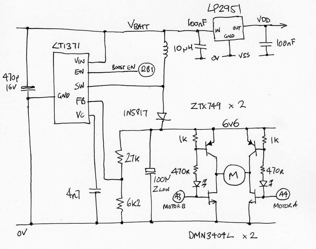
    Handily, I've acquired a few tubes of LT1371 Boost converters so the solution was to boost the battery supply up to a regulated 6V and regulate the 5V for the PIC with a Linear LDO. This was all made using SM parts soldered on the back of the stripboard:

    Top right: SM LT1371 legs splayed out to match 0.1" stripboard - works for me.

    Top left: ESP8266 add to provide IoT capabilities - naturally.

View all 2 project logs

  • 1
    Step 1

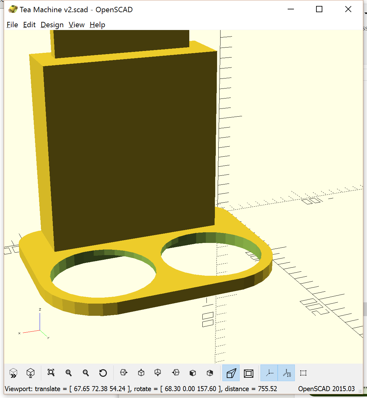
    I'm putting all the design files I have for this project on github - so far I've got the model for the box which although 2D Laser cut, was designed in Openscad. I actually use this along with Slic3r to generate Gcodes that drive my RepRap powered K40 Laser.

  • 2
    Step 2

    While the CAD files for the case should be good for all types of CD Drive, the electronics are going to have to fit in whatever space is left after removing the bulk of the original CD mechanism. All that's retained is the tray and front portion containing the motor, limit switch and eject button. Because of this and the fact that our one-off was made on stripboard, no PCB design is available. If you want to reproduce ChaiBot you will have take a similar approach or make your own tailor-made PCB layout.

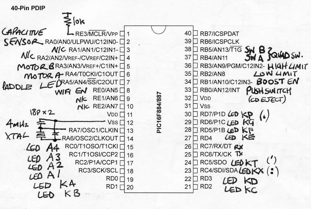
    One trick was to size the stripboard vertically such that the two battery holders squeezed in between the board and the end of the case. Three hand-drawn circuits provide everything except the detail of the rotary encoder and connections to the CD eject button. The firmware assumes that these three switches are all commoned to 0V.

    RB6, RB7, Vpp, VSS and VDD form the ICD programmer connections and are not shown. You will probably have your favourite connection method anyway.

    The two PNP high-side transistors could be replaced with P-Channel Mosfets. We didn't have any to hand at the time. The LED's (red) are there to drop ~2V to prevent turning on the PNP's when the RA3, RA4 are high ~5V and also serve as test indicators ;-)

    The display requires four NPN transistors connected as Emitter Followers to buffer the PA pins driving the common anodes. We used 2N2222 but BC182, BC548 etc. are all good here.

  • 3
    Step 3

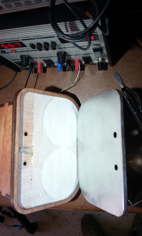
    The sensing of filling and removal of the cup(s) is handled by a capacitive weight sensor. A small screened lead connects between the PIC and a pair of thin aluminium plates. The active plate is situated below the two cup recesses and is glued to the underside of the uppermost plywood base part.

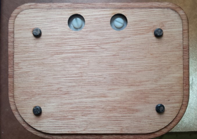
    The lower part of the base is composed of a thin perimeter glued to the upper part and the remaining inner cut-out section which is free to move within the perimeter (using the clearance provided by the laser cut). This supports the ground plate and the two plates are separated by paper masking tape. Four rubber feet on the bottom of the inner base part ensure that all the weight of the device is acting to push the plates together.

    To keep the coupling of any external electric fields to a minimum the underside of the cup recesses only have two joined circles slightly larger than the recess, while the ground plate is the full size of the base board. This shields the sensor plate from the worktop on which the device is placed.

    A loop of the outer screen of the connecting lead serves to make contact with the ground plate at the back edge when the base is in position - while the central conductor (just visible under the paper masking tape in the photo) joins to the sensor plate in the middle. This join can't be soldered to aluminium (which is what we used) but tin (e.g. buiscuit tin) might be an alternative material. In the case of aluminium we just stripped the insulation back a couple of cm and splayed the conductors out under the sticky tape.

    In operation 5V is applied to the top plate which builds up an electric charge between it and the ground plate then, when the voltage is removed, a timer is started and frozen some time later by the tripping one of the internal PIC comparators as the charge drops below a threshold. The time taken to discharge is proportional to the capacitance of the two plates which in turn is influenced by how much weight is squeezing the two plates together.

    While the two plates aren't actively sprung apart, their loose proximity is enough to make a relative measure of applied weight. One detail that may not be present in the CAD files are the locations of the two holes for the large Nylon bolts used to secure the CD drive in the box and retain the base plate.

    The position of these may vary depending on the type of drive used. We hot-melt glued two nylon nuts in the base of the drive to accept the bolts. The optimum location should be found and the holes added to the Openscad designs or they could just be drilled after assembly.

    Note that the nylon bolts prevent the base plate falling out altogether if ChaiBot is lifted and clamp the plate to the cable screen but also allow the small amount of movement needed to sense the force from applied weight above.

View all 5 instructions

Enjoy this project?

Share

Discussions

kristina panos wrote 04/07/2016 at 20:22 point

You're welcome! Coverage was well-deserved :)

  Are you sure? yes | no

Adrian wrote 04/07/2016 at 09:17 point

Great to see ChaiBot appear on http://hackaday.com/2016/04/06/chaibot-a-tea-robot-steeped-in-utility/ Thanks @kristina panos Further discussion is also welcome here!

  Are you sure? yes | no

Similar Projects

Does this project spark your interest?

Become a member to follow this project and never miss any updates