 Yann Guidon / YGDES
This circuit seems to work well in simulation, provided you let the first input stage settle for a while, as it charges the 10nF coupling cap.
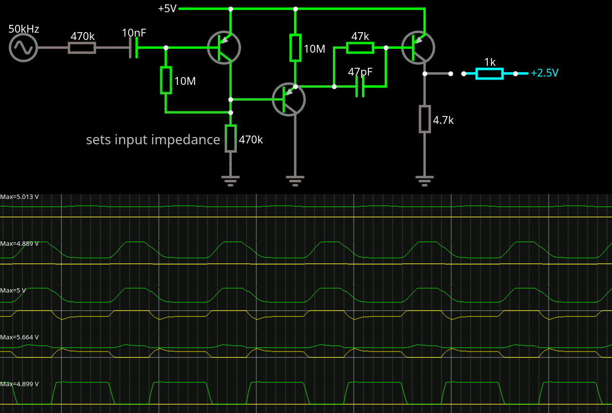
We have seen the first stage in a previous log so no need to repeat it : it uses the coupling cap as a reservoir too, so it takes a while for the bias to get "right" through the 10M resistor. On its own, it can amplify quite a bit, at least in amplitude. But the output drops as soon as some load is tied.
Then an emitter follower "buffers" the output. It acts almost as a Darlington pair with the 3rd but there are impedance issues so a RC network makes the junction.
Then a final stage does the saturated voltage amplification to get cleaner edges and a decent rise/fall time.
All transistors are set as hFE=20. Notice the various resistors : 470K, 47K then 4.7K, reducing impedance by 10x at each step.
The 10M pull-up has a strange behaviour in the simulation, as it raises the 3rd transistor's base above 5V, sometimes 6.5V depending on the capacitor and other factors. 47pF is "mostly harmless" but really helps with the output rise times.
The output signal drops when a load is tied, and I want to have even lower output impedance to drive 2 clock signals.
Of course the same usual limitations apply !
- The transistor of the simulation is not a Germanium type
- Leakage is not taken into account
- Baker capacitances are not considered either
So there will be quite a lot of differences but the simulation helped me understand the role of each part's value.
Discussions
Become a Hackaday.io Member
Create an account to leave a comment. Already have an account? Log In.
Your 10 nF coupling capacitor is far larger than necessary. At 50 kHz, its reactance is only 318 Ω which is insignificant compared to the 470 kΩ resistor in series with it.
Are you sure? yes | no
To be honest : it's an order of magnitude that does not really matter because ideally, I'll use a slower quartz resonator. I had found a 2400Hz resonator on eBay, and some others in the 8K-20K range. I wanted to test the circuit above the expected frequency to see what could slow it down (aside from the transistors themselves) and it's better to have a larger than an smaller capacitor. So the startup time is not really an issue...
But thanks for yet another useful remark :-)
Are you sure? yes | no
Even at that frequency it's still neglibible (6.6 kΩ) compared to 470kΩ. I suppose if looking through components in a spares box for a breadboard test then one can be lax, but this is exactly the sort of calculation engineers used to love to whip out their calculators for. Now that anybody can run free42 on their phone (well at least the RPN aficionados), it's not so impressive to whip out a calculator.
Are you sure? yes | no
@Ken Yap yes but.... The other factor is that I don't know the exact impedance of the source, it's very high but it is also very sensitive to downstream interference. I have artificially set the impedance to 470K as a rough estimate but maybe I'll even have to add a series resistor because the amplifier adds its own non-linearities that could disturb the crystal resonator.
So yes 10nF might be too high but there is no real limit to this capacitance (except time, money, space...). So it's a "spares bin" choice. However IF 1) the quartz is pretty slow (4800Hz ?) AND 2) the capacitor is too small, there is a risk of reinjecting undesired harmonics from the amp back into the crystal.
So 10nf is not harmful and could be reduced, it's a first order of magnitude. And I would like to reuse this circuit for more than one project, using different parts and sources and sinks...
Are you sure? yes | no
One of the boons afforded by ICs is the luxury of throwing more active elements at the design to increase universality. Discrete designs tend to have carefully chosen application specific values and/or trimming elements. For example the steering diodes in the discrete bistable are replaced by steering transistors in the IC version.
Are you sure? yes | no
@Ken Yap yes, which also explains why a lot of analog know-how and expertise has vanished... I'm slowly rediscovering all that.
But this rediscovery can have benefits for better IC designs too, in fact it's one of my motivations.
Are you sure? yes | no
It's a different design mindset though. For ICs, Q, D: use freely, R: when needed, C and high R: avoid, L: impossible. Also shift operations to the (precise) time domain from the analog domain.
Are you sure? yes | no
@Ken Yap I know :-) but IC design goes way beyond this rule of thumb.
Are you sure? yes | no
The circuit at the bottom of http://ua3vvm.qrz.ru/projects/html/gener.htm has a 330pF output capacitor, and 1000pF feedback, for 36KHz.
Now, is too much capacitance a problem ? Why ?
Are you sure? yes | no