Close
0%
0%

Hacking a $25 nRF51 ARM Cortex Activity Tracker

$25 wearable device development platform: nRF51 ARM CortexM0 w/ Bluetooth, accelerometer, 16x64 OLED, vibration motor, HR sensor, battery

Similar projects worth following
I searched high and low for the smallest activity tracker or smartwatch with a Nordic nRF51822 or nRF52832 ARM Cortex MCU. The M3 is what I found. Then I hacked it. nRF5X based activity trackers are my default early stage development platform for wearables and other small devices. They are cheap enough to be disposable (typically $20 for nRF51822 based or $30 for nRF52832 based), they have Bluetooth for internet connectivity, an OLED display, haptic feedback, a battery and battery charger. They are super simple to program with Arduino, ARM Mbed or the Nordic SDK. Having all this taken care of lets me concentrate on what I'm really interested in: design, sensors and data analysis. This tutorial is part of my Intraoral Respiration Monitor Overdose Detector Project: https://hackaday.io/project/106917-intraoral-respiration-monitor-overdose-detector

Check out my latest project Hacking Wearables for Medical Device Development. Inexpensive Arduino compatible nRF52 prototyping platform used by MATTER Lab. Tutorials & code for gesture recognition and machine learning.

M3 Specs:

Display: 0.69" 16*64 OLED

MCU/SoC: nRF51822 258kB Flash Memory 32kB RAM

Accelerometer: Kionix KX022-1020 using SPI interface

Heart Monitor: PixArt PAH8001 green LED PPG

Battery: 40 mAh lithium polymer

Waterproof: IP67

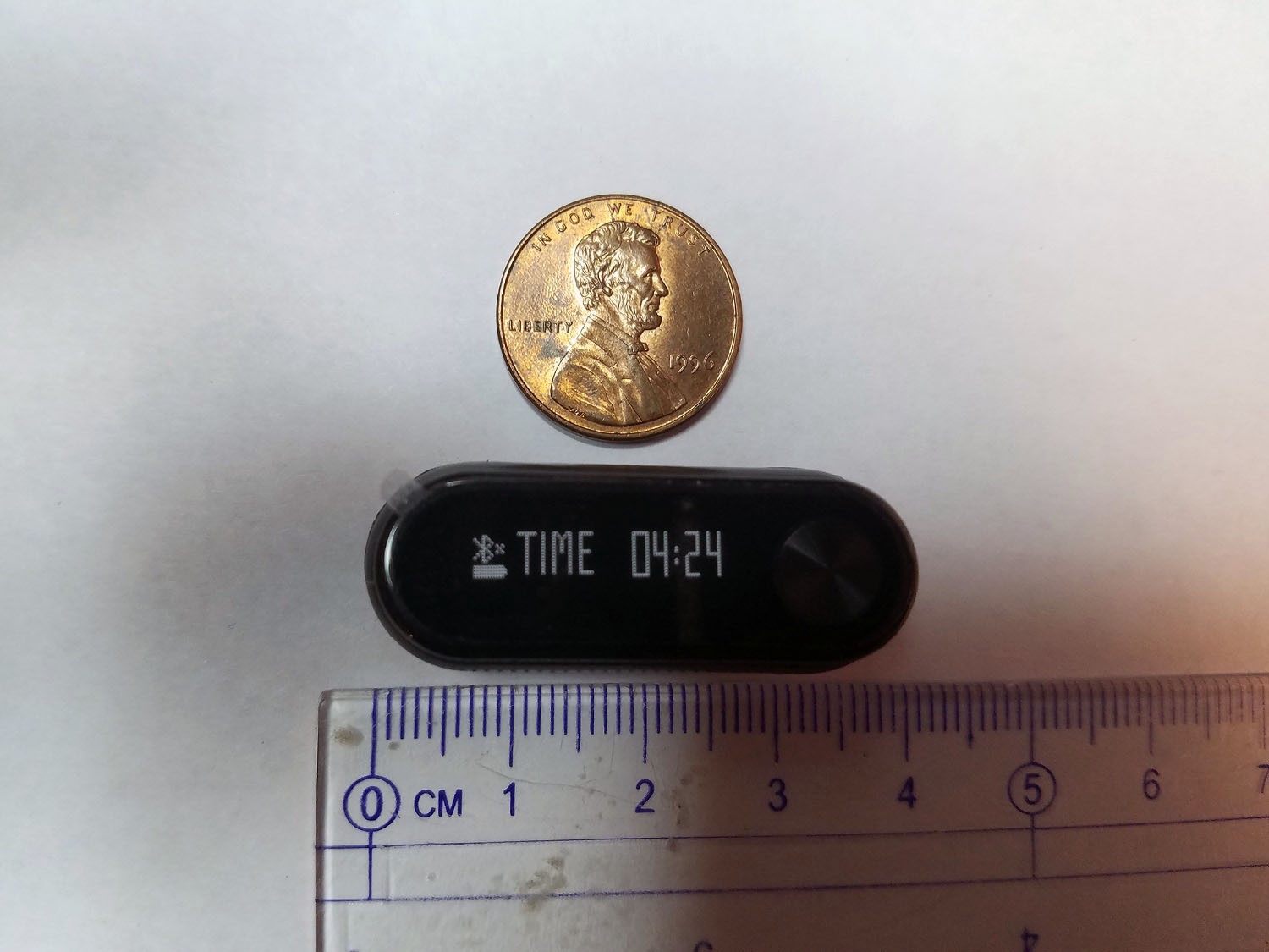
Device size: 18.0*11.2mm

This is a high resolution microscope image of both sides of the main board aligned so that pins and traces can easily be mapped. I currently use this for reference purposes when using the hacked M3 as a development platform.
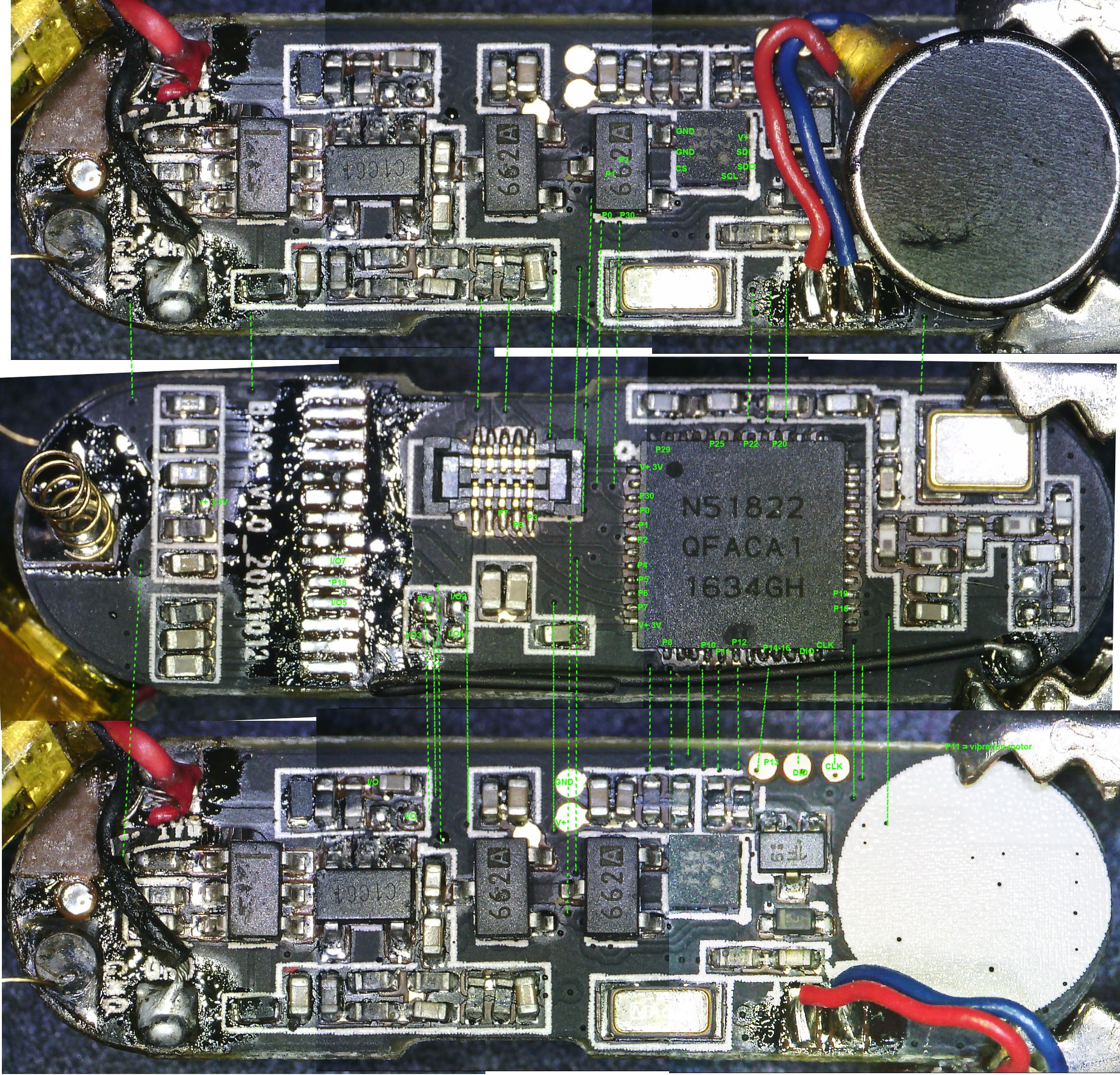
I've updated the GitHub repository to include information about a bunch of additional nRF52832 and nRF51822 devices I've hacked: https://github.com/curtpw/nRF5x-device-reverse-engineering

I plan on posting a lot more projects, on Hackaday and elsewhere. 

KX022 accelerometer code based on work by @goran-mahovlic and @rogerclarkmelbourne 

nRF51822_PS_v3.1.pdf

nRF51822 Datasheet

Adobe Portable Document Format - 7.02 MB - 03/28/2018 at 02:07

Preview

nRF51_RM_v3.0.pdf

nRF51822 Manual

Adobe Portable Document Format - 1.43 MB - 03/28/2018 at 02:06

Preview

nRF51_Pinout.jpg

nRF51822 pin diagram

JPEG Image - 120.33 kB - 03/28/2018 at 02:06

Preview

  • 1 × "M3" nRF51822 based activity tracker Look for it on ebay, AliExpress, Bangood and Amazon. Also try Google Image Search for "M3 nrf52822 activity tracker".

  • 1
    A Look at the M3 Activity Tracker

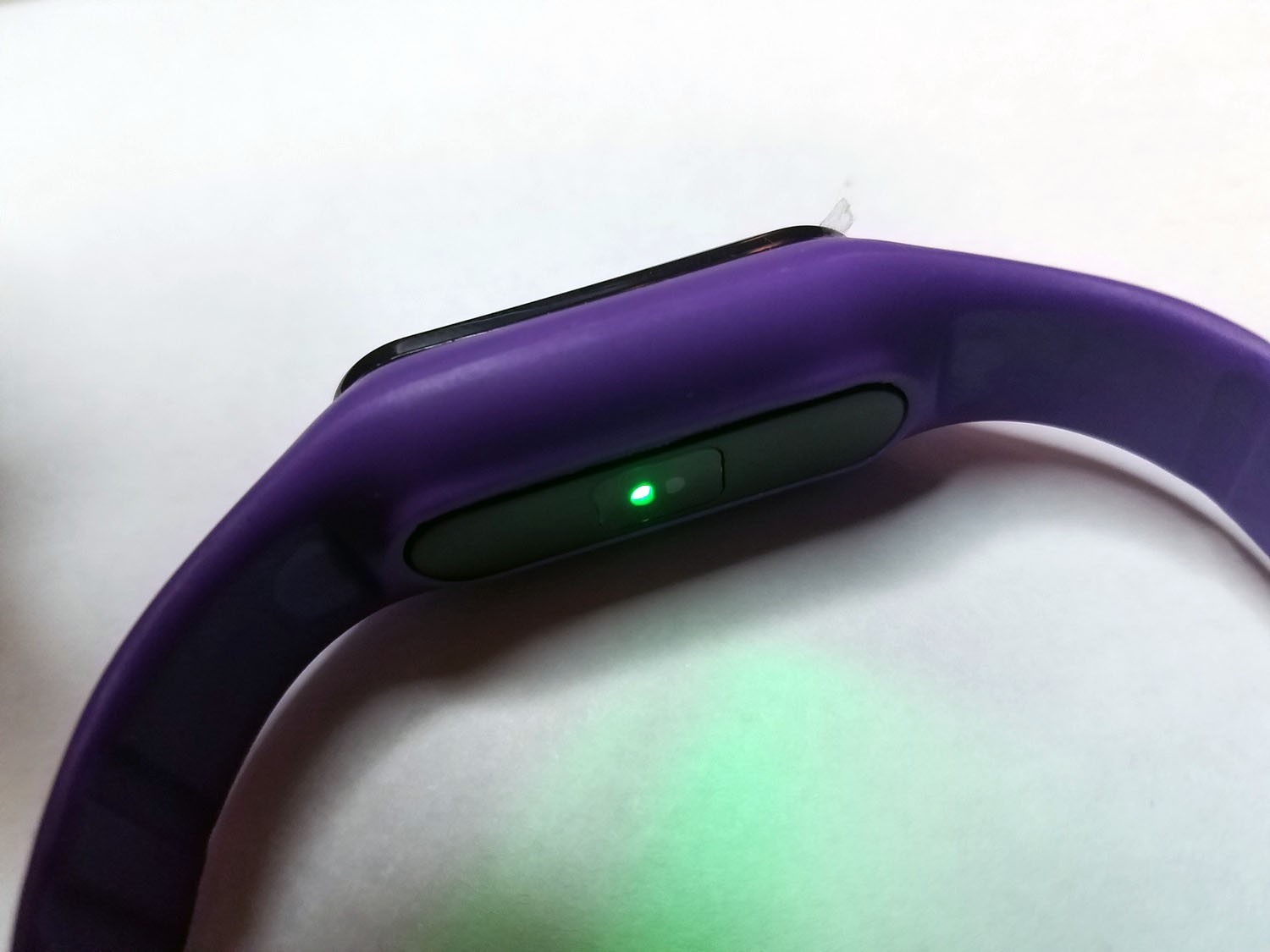
    Here is what the M3 looks like out of the box:

  • 2
    Enclosure Disassembly

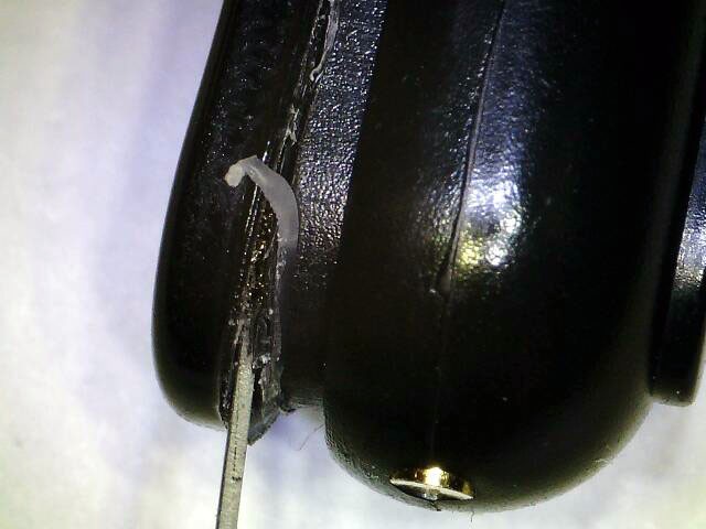
    The translucent enclosure cap of the M3 is glued to the opaque main enclosure body. The cap is not recessed into the enclosure body, it lies flat on top so it is fairly easy to remove. All you need is an X-acto knife (hobby knife, scalpel) and some patience. Run your knife along the corner where the enclosure cap and body meet. The idea is to slowly cut the glue bond and eventually wedge the cap and body apart. Patience is key. You might consider setting a 15 minute timer and repeatedly cut into the meeting point before trying to pry the enclosure cap and body apart.

    Eventually your knife will reach past the inside of the enclosure body wall. Start wedging the knife (or another small prying tool like a tiny flat head screwdriver) between cap and body. Work around the edge until the cap comes off.

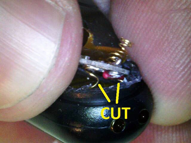
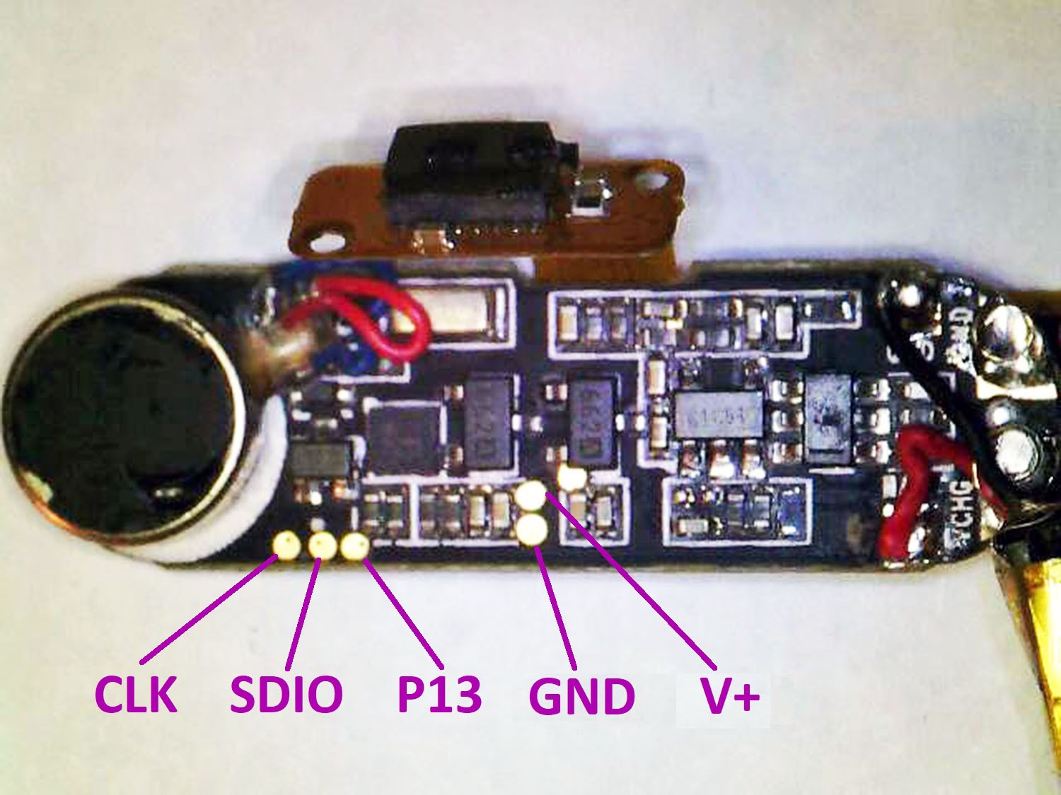
    In order to program the M3 you'll have to lift the main board and other components out of the enclosure body. The test pads for the SWD connection (SDIO & SDCK) and power are on the bottom of the board. The external connection points for USB charging are wired to the main board with little springs. The point at which this connection is soldered to the main board is extremely fragile. If you try to lift the board out of the enclosure without cutting this connection that solder points and connection traces will rip off the board.

  • 3
    Programming the Device

    You must use programmer that supports SWD interface. I use a Segger J-Link but there are many programmers that support SWD. You can even turn an Arduino into a SWD programmer: https://learn.adafruit.com/programming-an-m0-using-an-arduino/overview

    You must also use software capable of delivering the Nordic "Softdevice" (kind of like an OS) along with your code. I use the Nordic nRFGo Studio application: https://www.nordicsemi.com/chi/node_176/2.4GHz-RF/nRFgo-Studio

    There are a couple different projects that allow for programming nRF51/nRF52 based devices directly from the Arduino IDE: https://github.com/sandeepmistry/arduino-nRF5 , https://learn.adafruit.com/bluefruit-le-micro-atmega32u4-microcontroller-usb-bluetooth-le-in-one/using-with-arduino-ide

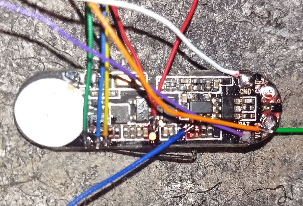
    First however we must wire up the programming connections on our M3 activity tracker:

    You can use P13 for serial debugging with any serial to USB adapter.

    Once you have your device wired up connect it to a power supply (3.3v) and your programmer. J-Link programmers are very handy and can be found for a very reasonable price on ebay:

    From here on all instructions assume use of J-Link programmer, J-Flash software for connecting to J-Link programmer and Nordic nRFGo Studio for actual programming.

    Download and install J-Flash software for J-Link programmer: https://www.segger.com/products/debug-probes/j-link/tools/j-flash/about-j-flash/

    Download and install nRFGo Studio for programming Nordic devices such as nRF51822 (what we use here with the M3), nRF52832, nRF52840 etc. : https://www.nordicsemi.com/chi/node_176/2.4GHz-RF/nRFgo-Studio

    Open J-Flash and select SWD programming interface and the nRF51822 MCU. Then open nRFGo Studio.

    Once you have succesfully connected to the M3 over SWD and wiped it's flash memory you are ready to program it with your own code. There are many ways to do this but for the purpose of this tutorial we will use the Arduino IDE with Sandeep Mistry's nRF5 Arduino Core. The nRF5 Arduino Core is essentially a wrapper around the Nordic SDK that translates supported Arduino code into corresponding Nordic SDK instructions. The nRF5 Arduino Core will allow you to compile and export your nRF51822 application as hex code which you can then load directly into the M3 activity tracker.

    If you haven't already, download and install the Arduino IDE. Then download and install the nRF5 Arduino Core: https://github.com/sandeepmistry/arduino-nRF5 

    The nRF5 Arduino Core uses "Variants" for a variety of devices and breakout boards. I've created a variant for the M3 activity tracker which you can find in the GitHub repository for this tutorial: https://github.com/curtpw/M3-nrf51822-activity-tracker

View all 4 instructions

Enjoy this project?

Share

Discussions

fanoush wrote 11/15/2018 at 11:29 point

Just to let you know there is another cheap (currently $8 !) nRF52832 based fitness tracker. I am documenting my efforts here https://github.com/fanoush/ds-d6  It is easy to open and get to SWD pins (just remove front glass https://pasteboard.co/HMcXmdl.jpg) and it has data pins on usb charging connector connected (DFU bootloader somehow uses it  - enabled as serial port 38400).

  Are you sure? yes | no

fanoush wrote 01/18/2019 at 15:05 point

just a followup that I have managed to figure out  the hardware details and update procedure and have Espruino build for DS-D6 with all the hardware accessible. You can build your stuff (or use my Espruino DFU package) and upload via nrfutil over serial DFU without needing to open the watch. So I consider this device fully hackable now with no compromises :-)

  Are you sure? yes | no

gabdaten wrote 04/17/2018 at 08:50 point

Thank you very much for your effort, I'll order some of these this afternoon. Thank you very much for making me aware that this cosmos exists :)

  Are you sure? yes | no

Curt White wrote 04/15/2018 at 17:23 point

M3 is the ID used by the manufacture, but most of the generic activity trackers coming out of Shenzhen (there are many, this just happens to be the smallest) are re-branded and sold by middle men of one kind or another. However, the same promotional images get used regardless of re-naming/re-branding so Google image search is very effective. For example I just used Google image search with the query "m3 40 mah 0.69 activity tracker". Here are some more links:

https://www.tvc-mall.com/details/bluetooth-4-0-smart-band-sports-bracelet-heart-rate-blood-pressure-monitor-purple-sku84110137d.html

https://www.joom.com/en/products/1490759736635174921-199-1-26341-3155568789

https://www.amazon.ca/Fitness-Tracker-Bluetooth-Bracelet-Pressure/dp/B072P1T8K2

https://sg.carousell.com/p/m3-smartband-bracelet-heart-rate-blood-pressure-monitor-109965786/

  Are you sure? yes | no

daid303 wrote 04/15/2018 at 09:08 point

I've ordered this https://www.aliexpress.com/item/ID115-Smart-Fitness-Tracker-Bracelet-Step-Counter-Activity-Monitor-Band-Alarm-Clock-Vibration-Bracelet-for-iphone/32795485892.html

With the intention of tearing it down, for $10 it would make a nice tinkering platform. I found some indication somewhere that it might have a nRF5X as well. But only found a low rest shot of the internals.

I'll report back once I  have it.

  Are you sure? yes | no

daid303 wrote 04/17/2018 at 10:06 point

Ok, it got in today. Good news is. This one pops open very easy, tiny bit of glue under the glass, but pressing and tilting a knife under each corner and it popped right open. And then the internal assembly can be taken out without much problems. Some double sided tape is holding the screen, battery, and buzzer motor with the PCB. Only the charging wires are fixed in the case, but are about 1.5cm long. So can be kept in place while removing the assembly. Allowing for a pretty much non-destructive disassembly.

Bad news is, not the nRF5X. The CPU is a RTL8762AG. Which does contain 512kb flash and 80k ram. So not to bad if I can put custom code on it. But not sure if any documentation on this chip is available.

The bottom of the PCB has some marked test pads: GND/VCC/VSS3, SCL/SDA, RX/TX, EN_G/HAND/HEARTH/PWR/LOG

EDIT: Found a copy of the datasheet. This lists 256kb flash, and 64kb ram, and seems to lack some data, but at least gives me a pin mapping.

  Are you sure? yes | no

Curt White wrote 04/22/2018 at 18:51 point

Ah, bad luck. I've accidentally gotten devices with Dialog or TI Bluetooth SoC in the past. Let me know if you have any luck. The model numbers that I cite in this project and on the GitHub repository for the project are proven nRF51822 or nRF52832 devices. I will be adding new device models and new hacks on a regular basis here: https://hackaday.io/project/144350-hack-35-wearables-for-medical-device-development

  Are you sure? yes | no

daid303 wrote 04/22/2018 at 19:52 point

Well, waiting till I'm back at the office, so I can take high res photos, and solder wires to the pins that are the SWD interface according to the docs. If I can dump the flash with the SWD interface, I might have a nice reverse engineering project on my hands. If not, I'm out of luck. The documentation I found so far is too limited as only thing to work with, it lacks info about the bluetooth and flash writting. I this chip comes with some special SDK normally, as I found 1 document mentioning it. Guess it's under heavy NDA, as no other references found to it.

  Are you sure? yes | no

Curt White wrote 04/23/2018 at 02:27 point

Sounds great! As far as IP goes, I would err on the side of caution and avoid posting anything you pull off the flash online. As far as working outside of official channels goes, I'm mostly familiar with projects revolving around Nordic and ST products.  Taking Nordic and ST as examples though, there is plenty of room for hackers and corporate gatekeepers to coexist in harmony.

  Are you sure? yes | no

Curt White wrote 04/15/2018 at 17:45 point

No, definitely not. This uses a Dialog MCU, not Nordic. I prefer Nordic chips over everything else for Bluetooth Low Power aka BLE aka Bluetooth 4. There are many generic activity trackers based on the nRF51822 and nRF52832 available to buy. However, the peripherals (accelerometer etc) will be different or at the very least will be setup on different GPIO.

  Are you sure? yes | no

Jarrett wrote 04/10/2018 at 22:43 point

Ah, this is so cool. $30 for a tiny Nordic M3 devboard with BT, an OLED and a healthy complement of sensors.

  Are you sure? yes | no

Curt White wrote 04/10/2018 at 21:38 point

I've updated the GitHub repository to include information about a bunch of other nRF51822 and nRF52832 devices I've hacked: https://github.com/curtpw/nRF5x-device-reverse-engineering

  Are you sure? yes | no

izzy84075 wrote 04/03/2018 at 18:21 point

I'm having trouble finding one of these. Any more tips on search terms?

  Are you sure? yes | no

Similar Projects

Does this project spark your interest?

Become a member to follow this project and never miss any updates