Close
0%
0%

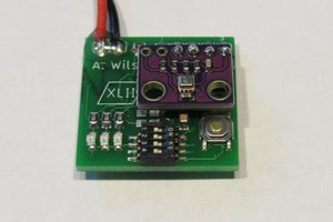
DS1307 RTC Breakout Board

A breakout board with the DS1307 Real Time Clock and battery backup

Similar projects worth following
This mini project was started to get some practical experience in circuit design / layout and improve my soldering skills.

I know I could achieve the same goal with ready-made breakout boards from Sparkfun or BangGood but I have an extremely tight budget and really need to practice basic design and soldering skills. The parts needed for this project cost me less than 2 euro (except the LCD and Arduino of course). That's a considerable saving on even the cheapest ready-made board.

  • 1 × DS1307 RTC IC realtime clock IC
  • 1 × battery holder for CR2032 coin cell
  • 1 × 100nF capacitor
  • 1 × 330 Ohm resistor limit LED current draw
  • 1 × LED every project needs a blinkenlight

View all 9 components

  • Step Two

    Mark05/04/2016 at 19:32 0 comments

    Finally received a shipment from China with some badly needed DuPont cables. That means i can can now hookup everything at once, finish the alarm clock software and publish the lot. I made a small breakout board with four switches to use as OK, Cancel, Up and Down buttons.

    More details to follow...

  • Build Log

    Mark04/18/2016 at 01:37 0 comments

    Been having a lot of fun with the LCD screen and a DS1307 Real Time Clock IC. After studying the schematics and DS1307 pinout, I made a breadboard sketch in Fritzing, tried it out and transferred the design to a small piece of stripboard. The usual pitfalls were encountered; a broken IC socket had to be de-soldered and replaced and I reversed the polarity of the coin cell holder. But I did end up with a functional 'breakout board' I can use in other projects. And I reckon a small side-step like this can only help in developing the skills needed to tackle a big project.

    I decided to make a new revised board, with proper pin headers and an activity indicator LED. The LED is toggled by the SQW (square wave) output on pin 7. This output is enabled by writing 0x10 to the DS1307 control register 0x07. The lower two bits control the frequency of the square wave and the default value of 0b00010000 equals 1 Hz, causing a slow blinking LED. Changing the register to 0b00010001 will set the frequency to 4096 Hz which produces a nice steady glow. Write 0b00010010 or 0b00010011 to select 8092 Hz or 32768 Hz and an even brighter LED..

    Musically inclined readers will have noticed that 4096 Hz and 8096 Hz are solidly within the audible range for humans. And it is very easy to hook up a small speaker or Piëzo buzzer and make this little chip beep. Or you could disable the SQW output and switch it on when a certain condition, like reaching a certain date or time, has been met... add a few buttons to set and cancel the alarm and hey presto: the digital alarm clock!

    The DS1307 has an added bonus of 56 bytes of storage space. It only takes 6 bytes to store a BCD DateTime. I will use one extra byte for alarm status (enabled/disabled) and another one for alarm type (once/daily/weekly etc). That leaves me with 56 / 8 bytes = 7 memory "slots" for alarms. Now all i have to do is write a clever piece of software that will allow me to set an alarm with two or three buttons.

    PS: when i had finished building rev. 2 I just couldn't get it working at all. I checked and double-checked all the obvious stuff (continuity, voltages) but the Arduino did not receive any data on the I2C bus. After a long time i more or less gave up and in a desperate last attempt, switched the SDA and SCL wires. Problem solved :)

View all 2 project logs

Enjoy this project?

Share

Discussions

Similar Projects

Does this project spark your interest?

Become a member to follow this project and never miss any updates