 Joshua Elsdon
Hello,
The last part went (rather quickly, see here for a longer version) over the soldering procedure for the SMD parts. Here I will present some of the steps to finish the robots.
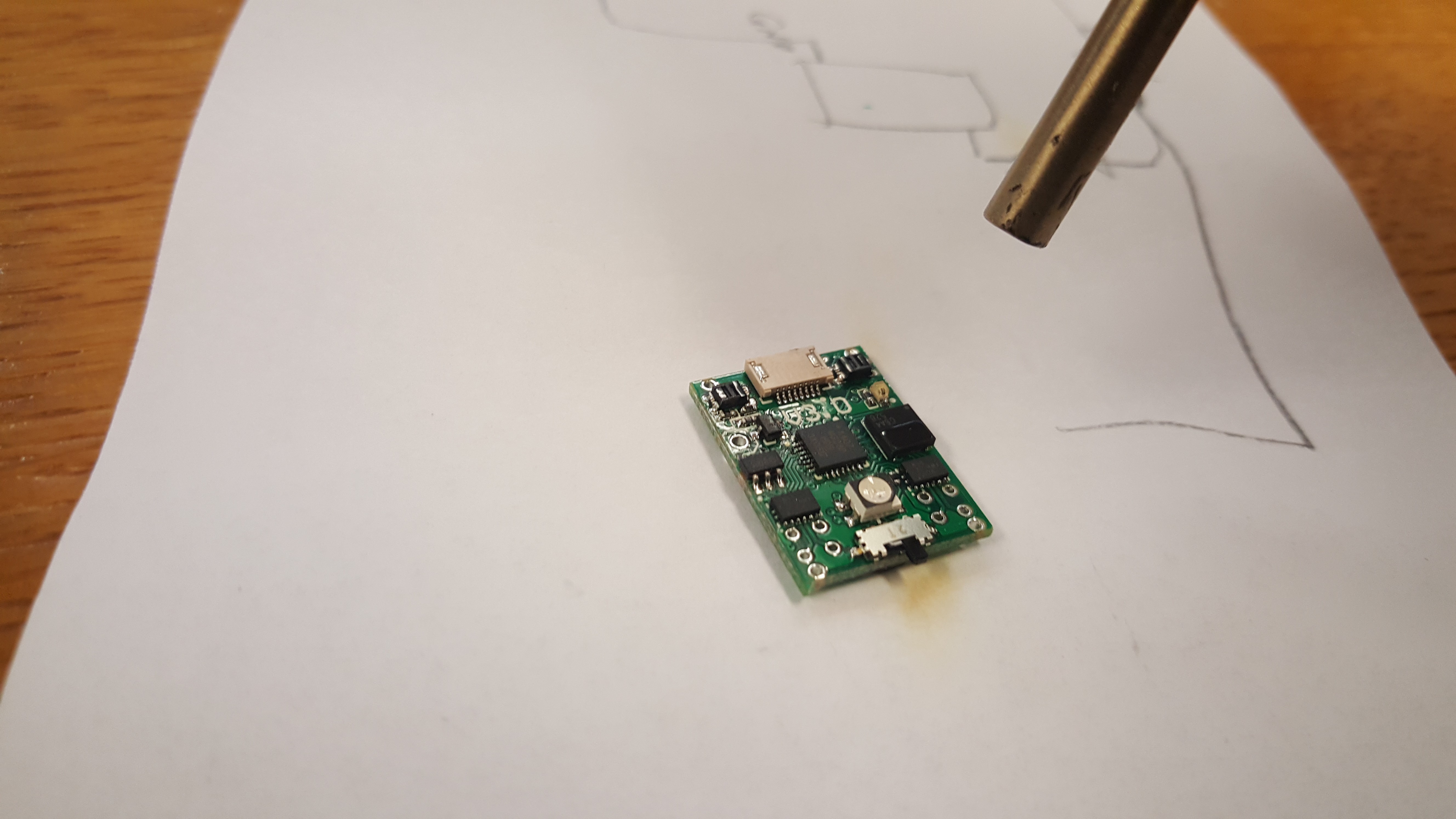
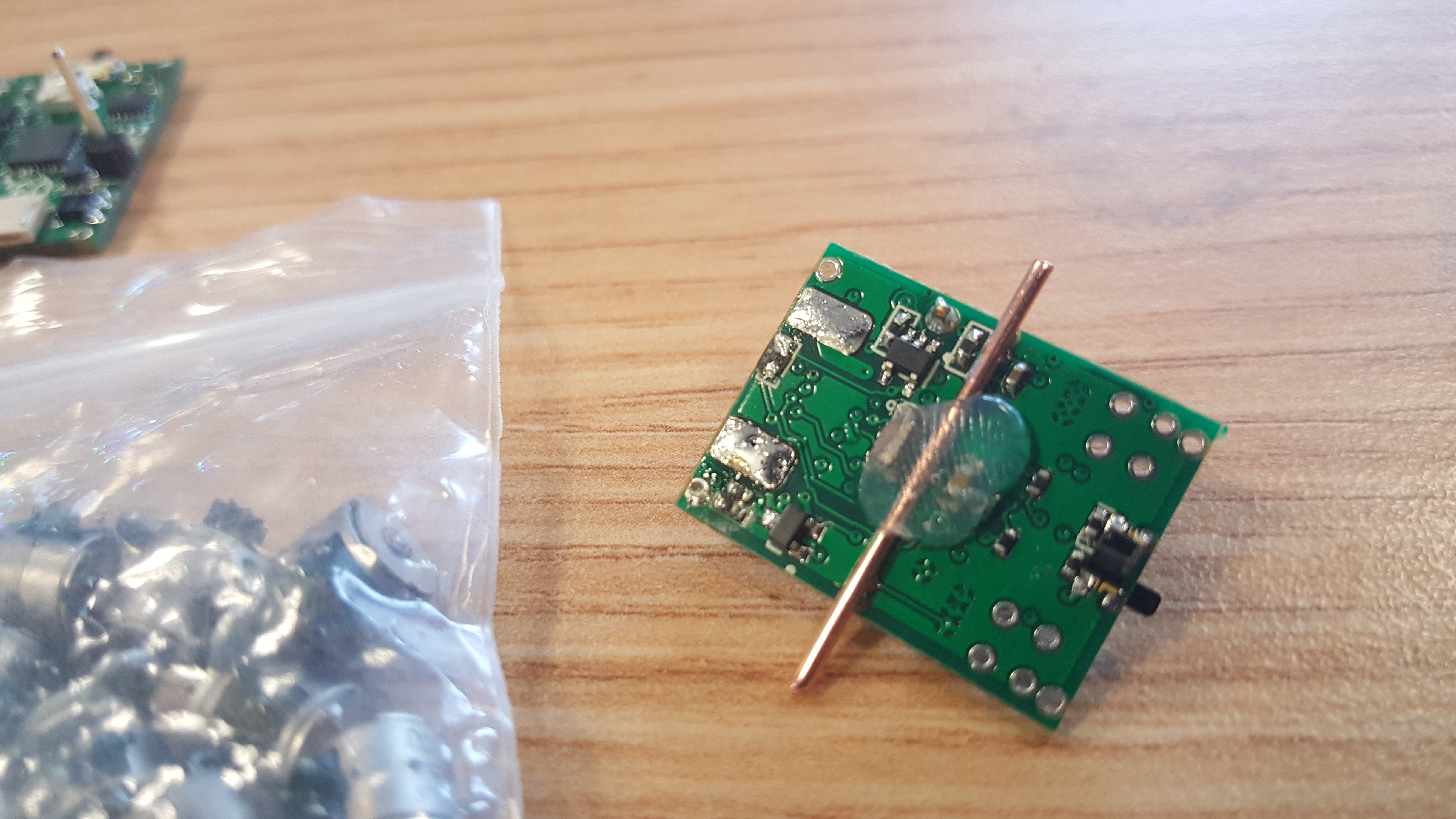
You may have notice that there was a component missing from the previous log, due to a shipping error it was not in the right place at the right time. Here I am placing it, the black square IR reciever (about the same size as the main chip), on top of the solder blobs that were left from the reflow process. Heat it gently at 300c with a hot air gun and it should connect to the pads with springy surface tension. I strongly recommend a 'proper' hot air rework gun, the over powered hair dryer kind will melt all the solder on the board, probably making a mess of things.
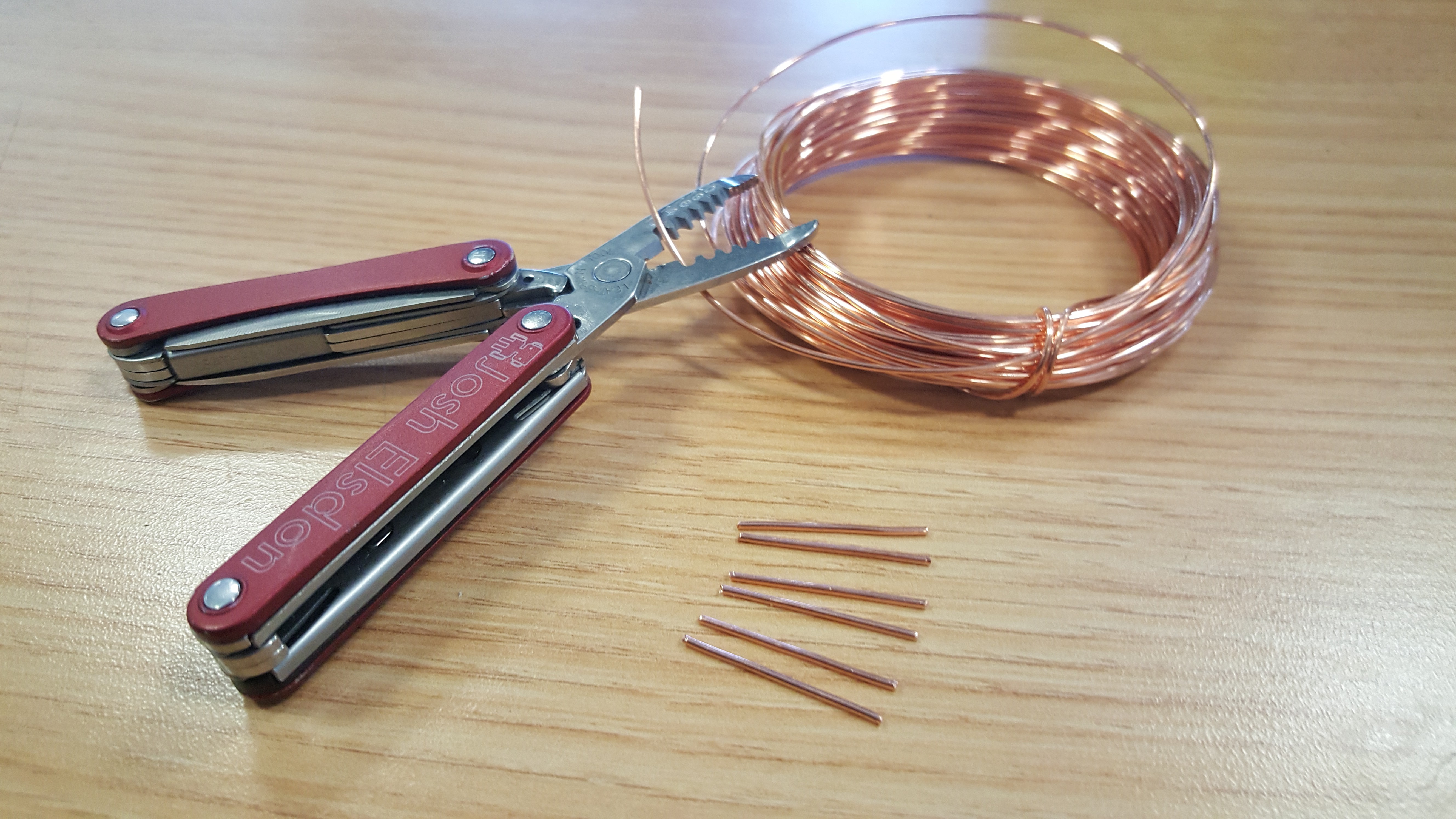
Making shafts is as easy as cutting short pieces of 1mm copper wire. Before I was using piano wire, but that stuff is hard and will ruin wire cutters (if you look carfuly you can see the scar on this set). Try and get the wire as bend free as possible. The length depends on how exactly you made your wheels. Mine came to 24mm.
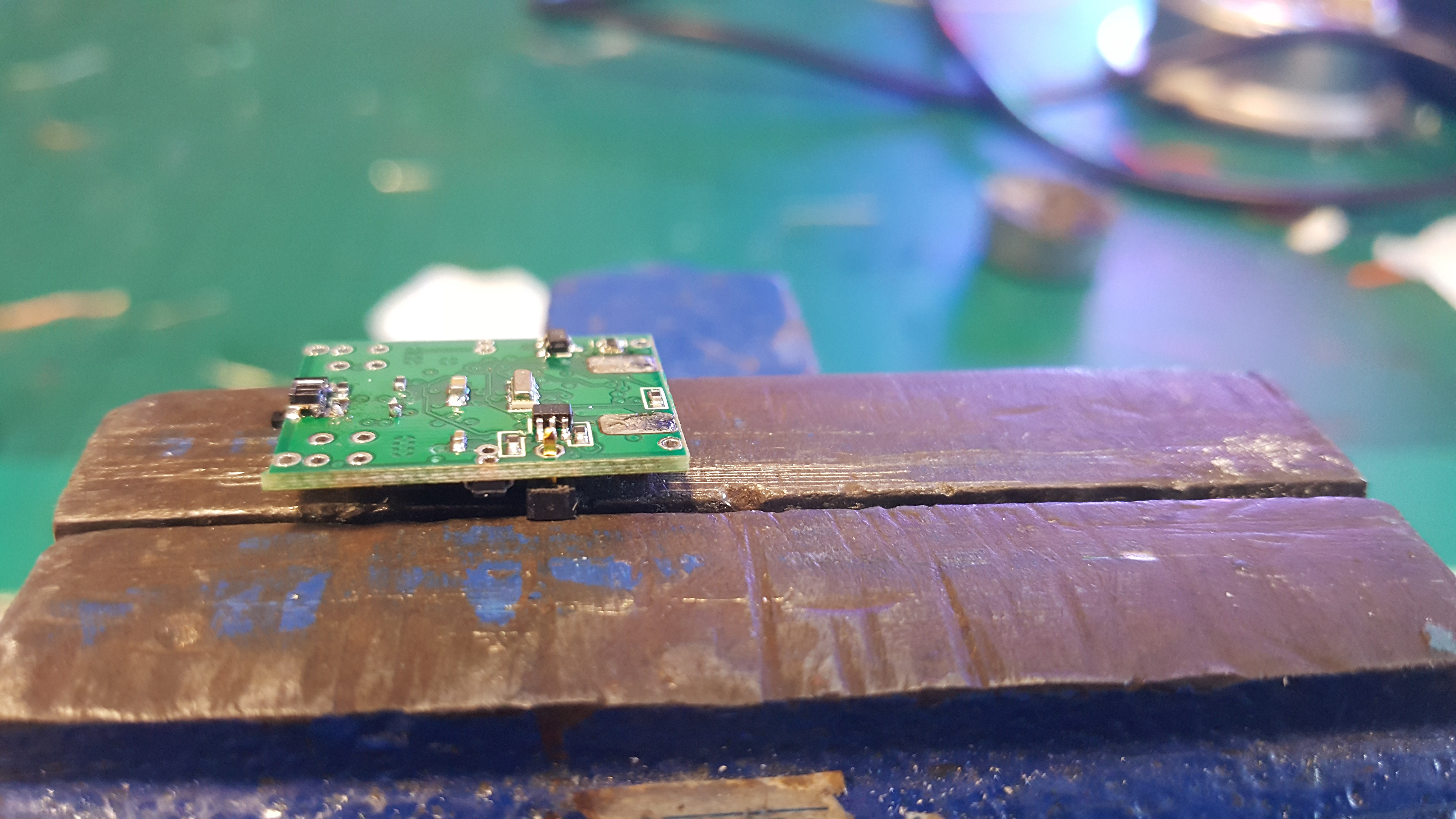
Next is soldering on the single pin header for the 'on the go' charging circuit. It is surprisingly difficult to do well as everything is so hot and small! I ended up wedging the header in a clamp and placing the board on top. Make the joint, then re-melt the joint whilst aligning it to make the header point directly 'up'.
I used hot glue to attach the shafts to the bottom of the board. We will need to 'reflow' this later to precisely line up the shafts, but aim for the middle.
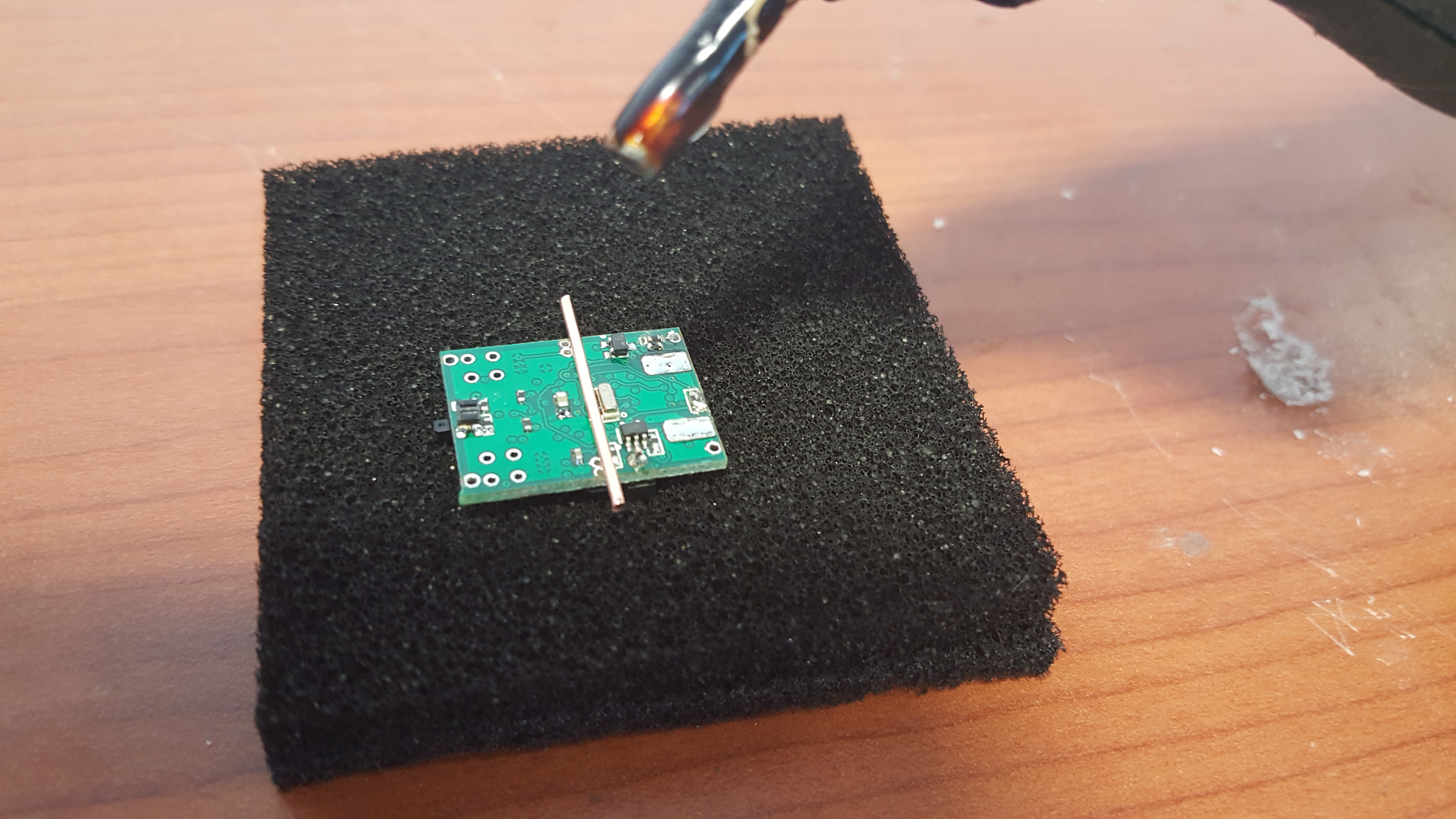
The result.
Soldering on the motors is another tricky task. Ideally you should make a jig to hold them in place. I went for the 'hold everything awkwardly in place with one hand and jab with the soldering iron with the other hand' method. The motors are very fragile, and you should handle them with the utmost care.
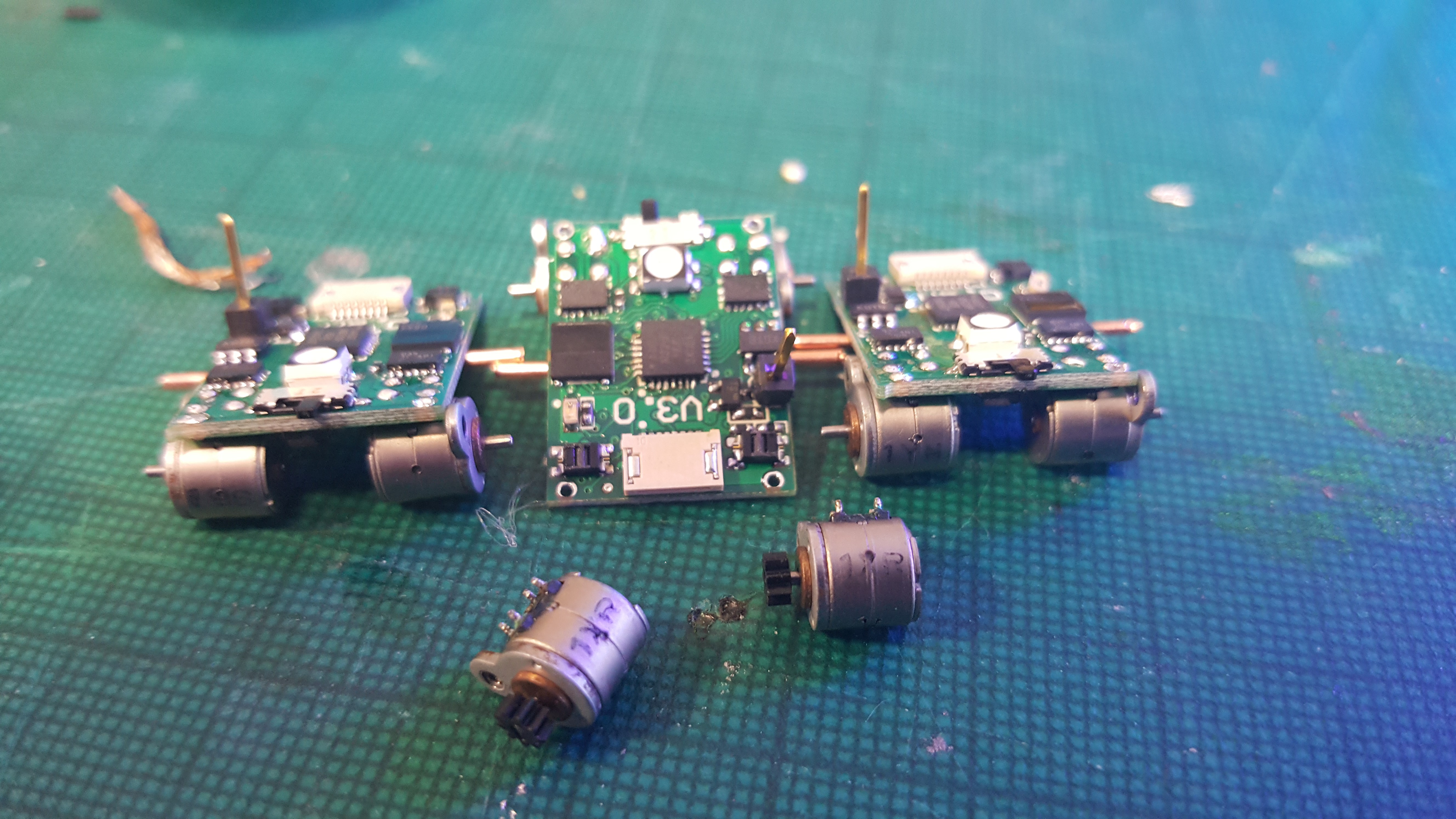
A shot of 5 robot sitting proudly with their new motors.
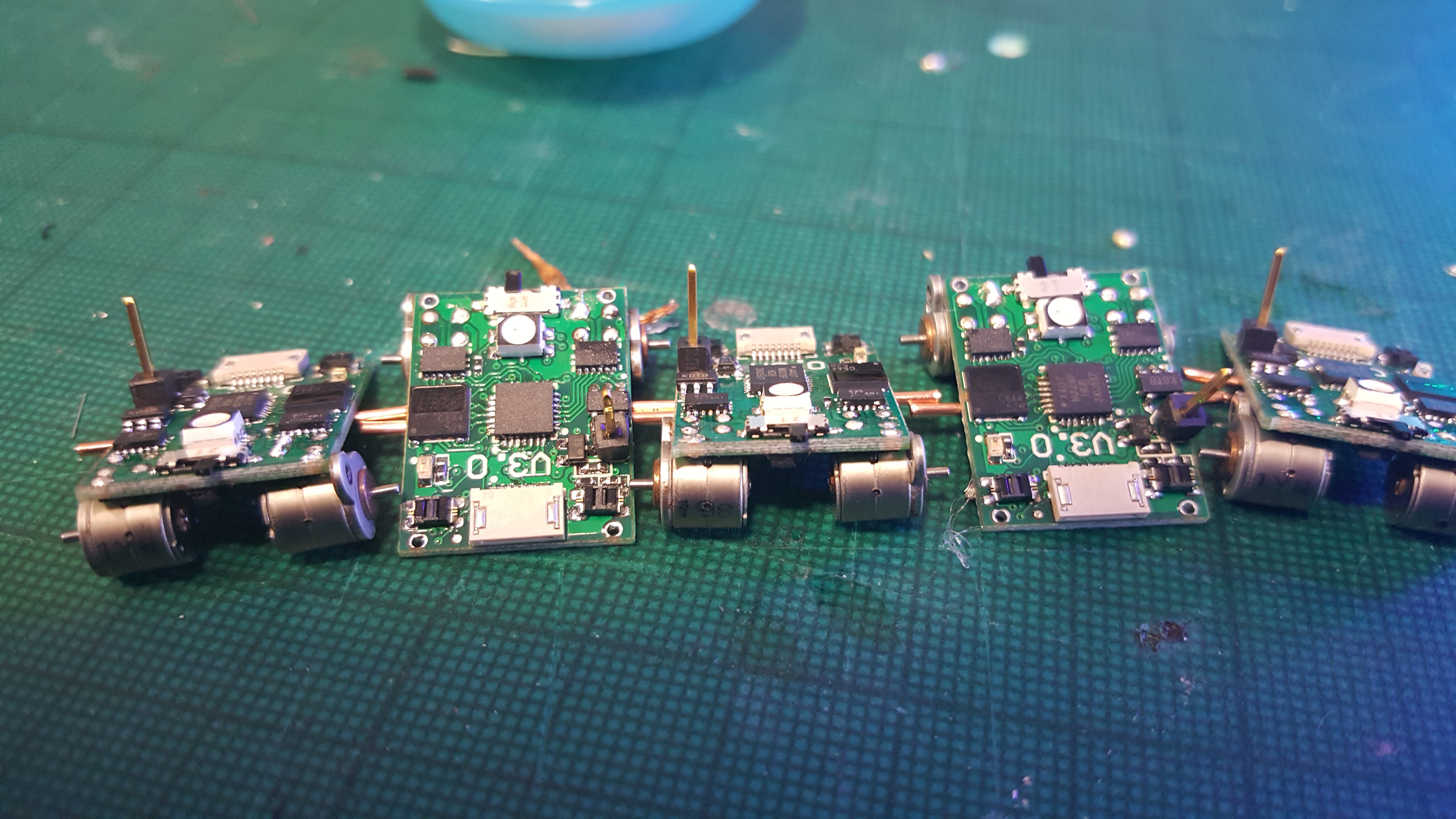
I forgot to take pictures of soldering the batteries. The key thing is to not make the battery short circuit. LiPo batteries do not like to be short circuited ;). The tabs need to be trimmed to size, check the pad size for reference. You will need lots of flux to get the connection to work, they use those horrid 'supposed to be spot welded' tabs, and they do not take solder well. Here is a bunch of 7 robots almost entirely finished.
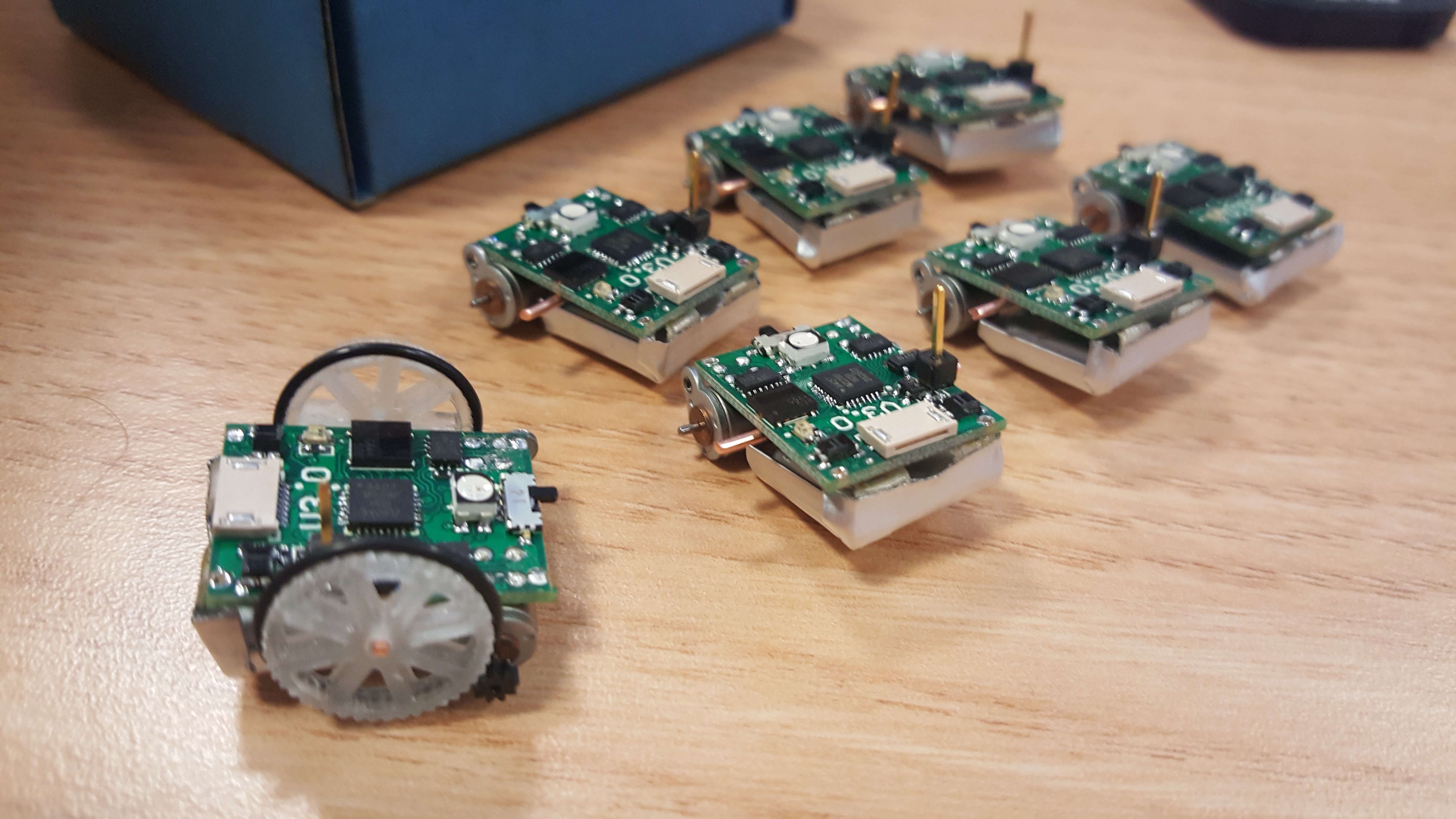
Fitting the wheels is a pain, any imperfections in them will make the motors stall, any misalignment of the shaft will make the motors stall. I think you get the idea, these are small robots and as such have limited torque, be prepared for a fiddly calibration of the drive train. This should be fixed in future versions with stronger motors, more precise wheels and a jig that aligns motors and shaft during assembly.
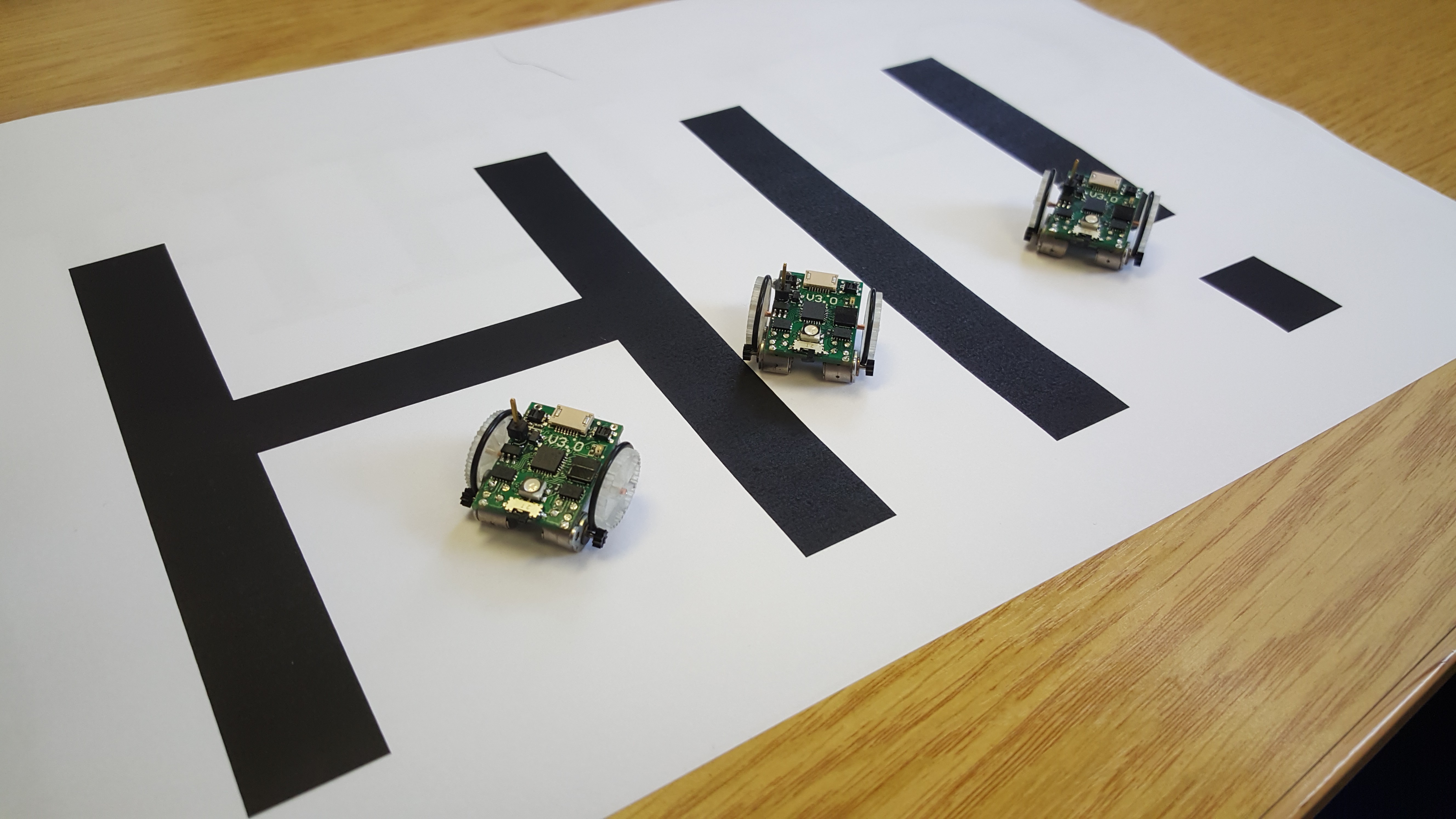
Hello from the little robots!
Discussions
Become a Hackaday.io Member
Create an account to leave a comment. Already have an account? Log In.
I wonder if you can't simply solder the shaft onto the board? It's copper, right? And you can make quite precise spots to place them, so re-aligning wouldn't be necessary?
I'm also wondering if it wouldn't be better to use something more like paperclip wire, and make it shaped like this "--._.--", with the middle part attached to the board, and the springy parts pressing the wheels against the motors.
Are you sure? yes | no
Hello, yes we came to a similar conclusion. V2.0 used a springy axle made from piano wire, this worked but was still pretty fiddly. V3.0, the current one, has grounded vias to solder an axle to, but this was not really rugged enough. After these experiments we have decided on copper shafts that are glued down. The glue is very rugged, and the copper is malleable with very little springiness (allowing us to make adjustments without the shaft returning to the original position). Ideally you want no pressure into the wheels, this will cause them to stall. Wheels with good tolerance should mesh with the pinion with little radial force. The next version is likely to use some kind of injection moulded wheel with a shaft that has been mounted at the same time as the motors using an assembly jig. This should get us the tolerance needed. Finally we are also negotiating some stronger motors from a Chinese supplier, they should help us power through any sticky spots on the wheels.
Are you sure? yes | no
Nice. If you are doing injection molding anyways, you might consider making a plastic holder for the board and motors, with axles built in.
Are those the stepper motors commonly used to move the lens in cameras?
Are you sure? yes | no
(seems I cannot reply to your nested comment) Yes I suppose I could make a axle/chassis, cool idea. I probably should make an enclosure for it. I will see if we have space on the board for registration holes, maybe we can make a sandwich (with injection molded parts being the bread) that have an axle in them.
Are you sure? yes | no
Wow, Awesome!
Are you sure? yes | no