Joe Mendia
-
7 inch and 4.3 inch boards ready
05/30/2016 at 21:55 • 0 commentsI have been a bit busy these days but I managed to solder the base board for the 7 inch LCD and another 5 inch base board for further testing. One good thing about this project is that the base board for the 5 inch LCD can be used with a 4.3 inch LCD with no modifications at all.
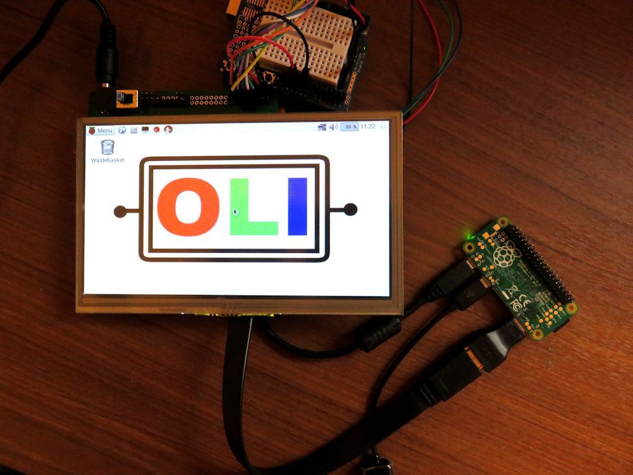
Here you can see the 7 inch being used with a Raspberry Pi Zero, the Arduino was wired for other test and left there.
![]()
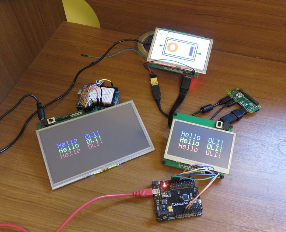
Here for a size comparison I show you all the LCD's I have tested, the top one being used by the Raspberry Pi zero is the 5 inch with the HDMI module (yellow board), the 7 inch is on the left used by the arduino and the one on the right is the 4.3 inch used with the arduino. The two LCDs connected to the arduinos have the SPI module on the back (red board).
![]()
Next I show you here a small side by side test run with the 3 LCD's working together, the touch screen is working with the SPI video module (red board) but not yet with the HDMI board, that is one of the next steps. If you see the detail picture of the yellow board, you will see some missing components that are there to translate the touch screen to USB.
I found some image quality issues with the 7 inch base board, I think the length of the H_SYNC, V_SYNC and color lines is the problem. With the SPI video module this is not an issue because the frequency is much smaller than with the HDMI, a detail to take care for the next version of the base boards.
![]()
-
OLI first test
05/25/2016 at 18:59 • 0 commentsHere I show you a test using the first OLI board with a 5 inch LCD using an Arduino UNO and a Raspbery Pi Zero
-
Origin and explaination of the OLI
05/24/2016 at 23:03 • 0 commentsHere I explain the OLI in detail
-
Base boards for 4.3", 5" and 7" Screens
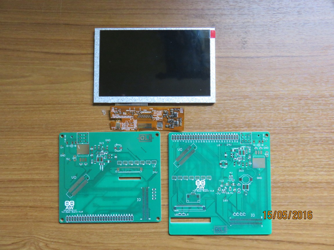
05/15/2016 at 18:32 • 0 commentsOnce the proof of concept of OLI worked was time to separate the circuits for 40 pin LCD's (4.3 and 5 inch) and 50 pins LCD (7 inch). The initial base board had the power circuitry for both types of LCD's. Now with these new PCB boards the power circuits are separated and now will be possible to test individual sizes of LCD's with the diferent video modules (SPI module and HDMI).
![]()
LEFT:PCB for 40 pin LCD's, RIGHT: PCB for 50pin LCD's, TOP: 5 inch LCD
The next step this week will be to populate the boards and start making tests!
-
OLI proof of concept
04/26/2016 at 16:54 • 0 commentsAfter clearing the idea of OLI and in order to proof the concept I designed the first base board to be used to test the modular design behind the OLI.
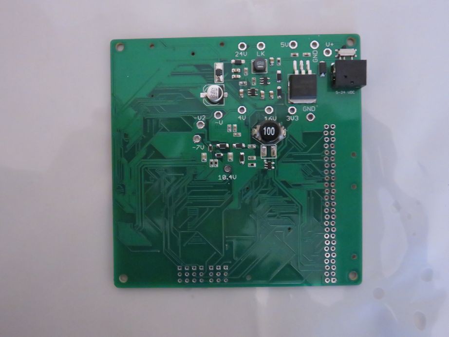
Here is the first board with the power circuitry soldered by hand.
![]()
This board was made in order to generate the different voltages (3.3V, 4V, 10.4V, 16V, 24V and -7V) needed by the 7" LCD and to break the 24 RGB signal to a connector to attach the video modules.
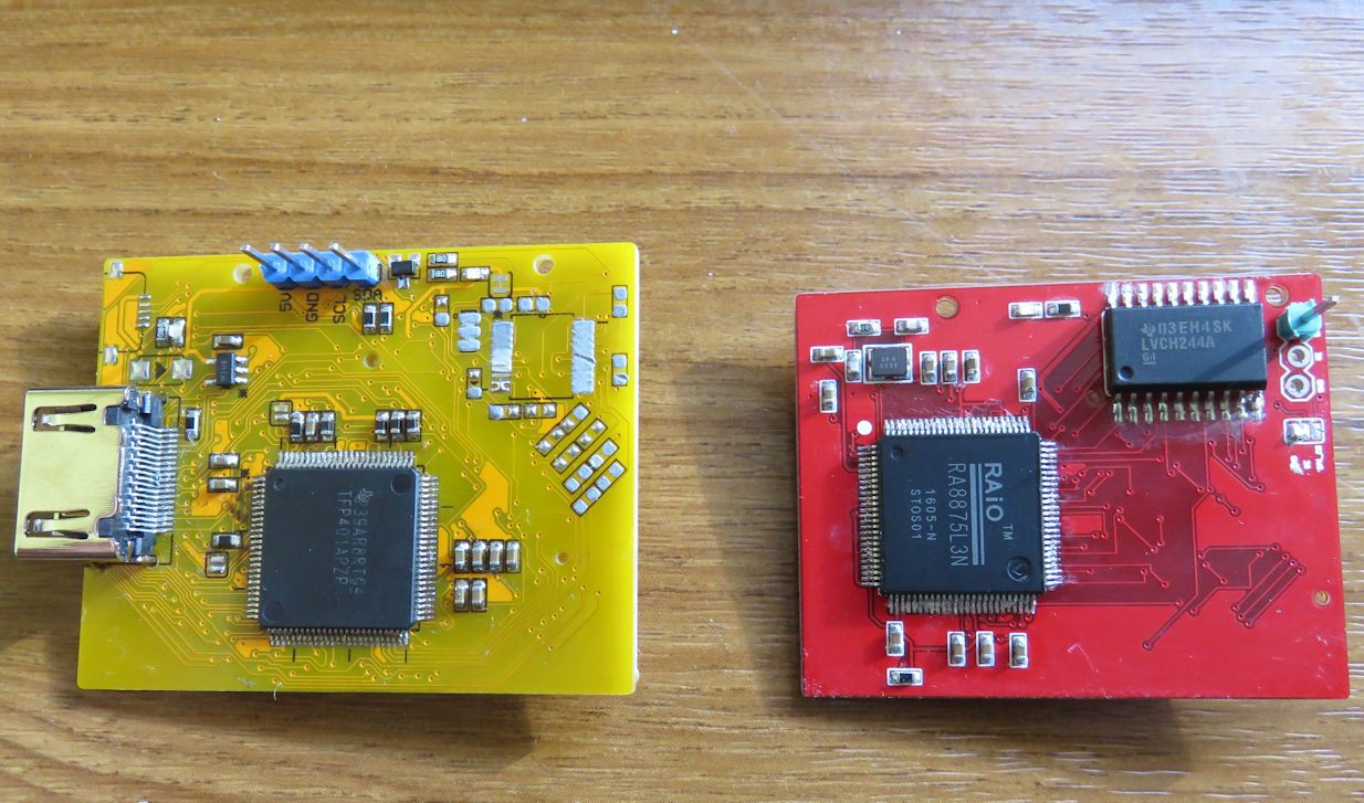
For the video signals, two PCBs were also made, the yellow one is a HDMI decoder based on the TFP401A and the red one is based on the RA8875.
![]()
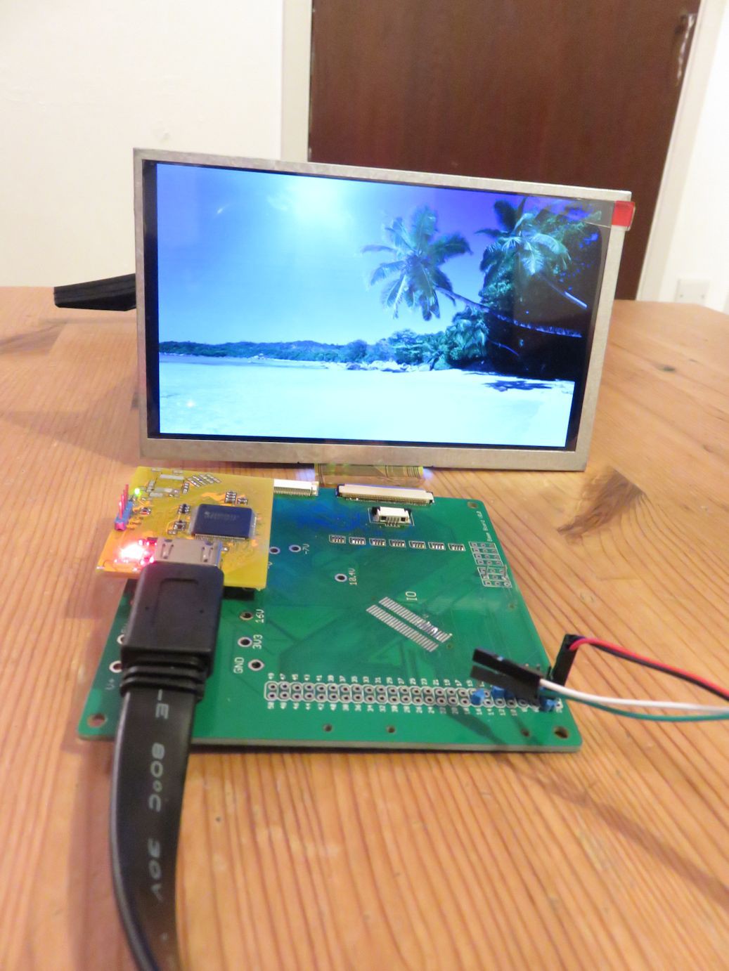
The test of the yellow one with the base board can be seen here:
![]()
The HDMI signal is from my laptop showing an image, the quality is quite good. Based on this tests I have concluded that the concept is feasible and will have to refine the base board design.
Here you can see a video testing the 5" LCD with a HD Video from youtube. The 40p connector to the LCD in the main board has a fault and the colors are not nice so I have connected it to the 50p interface of the base board and it works great.
OLI (Open LCD Interface)
Open Source interface to connect LCD's (5" and 7") to any Board/Micro-controller using HDMI and SPI